1
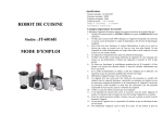
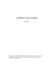
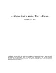
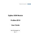
MultiCONT Manufacturer: NIVELCO Process Control Co. H-1043 Budapest, Dugonics u. 11. Phone: (36-1) 889-0100 Fax: (36-1) 889-0200 E-mail: [email protected] www.nivelco.com prw11a1a0600p_02 1 / 60 CONTENTS 1. INTRODUCTION ..................................................................................................................................................................................3 2. TECHNICAL DATA..............................................................................................................................................................................3 3. OPERATION ........................................................................................................................................................................................4 3.1 Electrical layout ........................................................................................................................................................................................................ 4 3.2 Connecting MultiCONT programming units via RS485 interface ............................................................................................................................. 5 3.3 Recommendations for building a network ................................................................................................................................................................ 5 3.4 Application example ................................................................................................................................................................................................. 7 4. DATA TRANSFER ...............................................................................................................................................................................8 5. DATA TYPES.......................................................................................................................................................................................9 6. DESCRIPTION OF THE HART PROTOCOL..................................................................................................................................... 12 6.1 Command structure ................................................................................................................................................................................................ 13 6.2 Commands ............................................................................................................................................................................................................. 16 7. MODBUS RTU PROTOCOL .............................................................................................................................................................. 41 7.1 Reading bit variables (FNC=01h) .......................................................................................................................................................................... 44 7.2 Reading tables, variables (FNC=03h) .................................................................................................................................................................... 46 7.3 Checking of bindings (FNC=08h) ........................................................................................................................................................................... 55 7.4 Remote programming of the transmitters (FNC=17h) – HART over MODBUS –................................................................................................... 56 2 / 60 prw11a1a0600p_02 1. INTRODUCTION The USER RS485 interface of the MultiCONT provides the possibility of serial data transfer to the central process control computer or PLC. Using HART over MODBUS or HART over HART communication protocol there is a remote programming possibility of the connected transmitters to change the identification and operational parameters. This case the MultiCONT acts as a bridge in the communication. Moreover it is possible to query the following values: - Measurement values of the transmitters - System configuration (MultiCONT settings, relays, current outputs, number of universal interface modules and its settings) - Relays and current outputs assigned to the transmitters - Error list 2. TECHNICAL DATA Serial data format Input resistance (K1 open) Built-in terminal resistor UIN=12V Input current UIN=–7V Input ESD Impulse Protection DC galvanic isolation Communication protocol (selectable from menu) Connection cable 9600 BAUD, 8bit data, ODD parity, 1 STOP bit 20 k 120 0.9 W max. 1 mA max. –0.8 mA Imax (8/20 s)=400 A Wmax=1.5 J (2 ms), 8kV ESD 500 VRMS HART 5 or MODBUS RTU STP (Shielded Twisted Pair) prw11a1a0600p_02 3 / 60 3. OPERATION 3.1 ELECTRICAL LAYOUT MultiCONT unit The RS485 interface converts the TTL-level asymmetric (unbalanced) full duplex serial signals of the MultiCONT to standard RS485 symmetric (balanced) half-duplex signals. Terminate the „A” and „B” cables of the interface with the 120 resistor enabled by the K1 switch. Rx Tx GND Galvanic isolator RS485 converter K1 Protecting circuit Figure 1: Scheme of the RS 485 interface A 21 B 22 COM 120 Terminal resistor On Off MultiCONT K1 K1 A B COM 20 21 22 Figure 2: Position of the connection terminals and K1 switch 4 / 60 prw11a1a0600p_02 20 The K1 switch is beside the connecting terminals. A K1 A K1 120 B 120 B 3.2 CONNECTING MULTICONT PROGRAMMING UNITS VIA RS485 INTERFACE MultiCONT units can be arranged in a network via the RS485 interface. This way a very simple, cost-effective 2-wire STP network can be set up. When setting up the network, the instructions for building a computer network should be taken into consideration (chapter 3.3.) 3.3 RECOMMENDATIONS FOR BUILDING A NETWORK The most important thing is that the communication line should be closed on both ends with terminal resistors and only at the two farthest points. The value of the resistor depends on the wave impedance of the used cable. The interface has a 120 terminal resistor, so the cable should be chosen considering this impedance value. A MultiCONT Central process control computer K1 B A B K1 MultiCONT A B K1 MultiCONT A B K1 MultiCONT Figure 3: Example of an incorrect network prw11a1a0600p_02 5 / 60 T. res. 120 T. res. 120 A B A K1 MultiCONT B K1 MultiCONT A B K1 MultiCONT A B Central preocess control computer No terminal resistor!!! MASTER T. res. 120 T. res. 120 A B K1 MultiCONT A B K1 MultiCONT A B Central preocess control computer A B K1 MultiCONT A B K1 MultiCONT MASTER Figure 4: Examples of correct networks Incorrect configuration is where there are more than 2 terminal resistors or they are not on the (2) farthest points of the line. (Fig.3). In such cases, especially when using too long connection cable, data transfer errors may occur. The MultiCONT units should be connected one by one on the cable (Fig. 4). Star topology is not allowed! The max. cable length is 1000 m but In this case always use STP (Shielded Twisted Pair) cable. Cable capacitance must be less than 100 pF/m. Shielding must be grounded only at one point to the ground of the central process controller computer. Shielding must be connected to the COM terminal. MultiCONT units connected in a network should have distinct addresses (1…31) see „Main menu” / ”MultiCONT config” / ”HART”/”Short address” in the USER’S AND PROGRAMMING MANUAL. There can be only one master (process control computer, PLC) in a system. Note: If a system is installed in an environment with heavy electromagnetic disturbances it is possible that the internal protection of the interface is insufficient to withstand the voltage impulses. Only those types of (over voltage or lightning) protection can be used on the A-B terminals of the interface that don’t affect data transfer process. This means that it should not cause a change in the transfer characteristics in the –7…+12V voltage range (with regards to the COM terminal). As a result, we recommend the use of STP cable when transferring data over long distances. 6 / 60 prw11a1a0600p_02 3.4 APPLICATION EXAMPLE The „network” consists of the following devices: - Central process control computer - 3 pcs of PR_-1_A or PR_-1_B type MultiCONT MultiCONT Device 1 K1 off Central Process Control Computer MASTER A B COM 20 21 22 MultiCONT Device 2 K1 on A B COM 20 21 22 The MultiCONT units have different addresses: A B COMMON Ex.: address of device 1 = 01 address of device 2 = 03 address of device 3 = 12 MultiCONT Device 2 K1 on A B COM 20 21 22 No terminal resistor!!! Figure 5: system structure mentioned in the example prw11a1a0600p_02 7 / 60 4. DATA TRANSFER Data transfer in the network established between the MultiCONT controllers and the central process control computer is in accordance with the protocol described in chapters 6 and 7. Data transfer is initiated by the MASTER (only one MASTER can be in the system). Each MultiCONT has its own address (1…31), see: “Main menu” / ”MultiCONT config” / ”HART” / ”Polling address” menu point in the USER’S AND PROGRAMMING MANUAL. The process control computer (MASTER) uses these addresses when initiating the communication with the MultiCONT units. Properties of the serial data transfer: Data transfer speed (BAUDRATE) Data length Parity Number of stop bits 9600 8 bit none, even, odd 1 or 2 The central process control computer sends a command to the MultiCONT unit and then waits for a response. The length of the response varies, so for content description see: chapter 6. (HART) and 7. (MODBUS). To ensure data transfer reliability every command and response is equipped with either a CRC code (MODBUS) or an FCS checksum (HART) which enable error detection. If there is no response from the MultiCONT the causes may be the following: - Broken cable (When the system is turned off, using an Ohm-meter 60 can be measured between points A and B at the terminal of any device) - points A and B are inverted (does not damage the device) - the address of the device has changed - Due to noise on the data transfer line the MultiCONT is unable to interpret the relevant command and does not respond, or the central process control computer cannot interpret the response. In such cases the commands should be repeated. It is also useful to check the grounding of the cable shielding. Shielding that is not grounded (or grounded at multiple points) may generate noise on the line! - terminal resistors are not present or connected at wrong points. - there are multiple MASTER units in the system and they jam each others communication 8 / 60 prw11a1a0600p_02 MultiCONT flashes a „ * ” character when interpreting a relevant command and this helps in discovering errors. A 600 ms flash appears each time the MultiCONT receives and interprets a command 1:SE-300-1 LEV M 5.345 m 3 5. DATA TYPES The following data types can be found in the responses: 5.1. String This is a sequence of ASCII characters ending in 00h e.g.: string = aba123 byte-sequence: 41h 42h 61h 31h 32h 33h 00h 5.2. Packed: Packed string (HART protocol) In string variables the 8 bit ASCII characters are packed into 6 bits (4pcs. of 8 bit character fit into 3 bytes) as shown below: 0 1 2 3 0 1 @ A P Q SP ! 0 1 2 B R „ 2 3 C S # 3 Packed ASCII character set 4 5 6 7 8 9 A B D E F G H I J K T U V W X Y Z [ $ % & ’ ( ) * + 4 5 6 7 8 9 : ; C L \ , < D M ] = E N ^ . > F O _ / ? prw11a1a0600p_02 9 / 60 e.g.: P-58 in compressed format Byte N 0 1 0 0 0 0 1 0 P 1 1 0 - Byte N+1 1 1 1 0 1 1 5 1 1 Byte N+2 1 1 0 8 0 0 In HEX format: 42h ddh f8h 5.3. Float: Floating point number An IEEE 754 standard 4 byte long single precision floating point number Byte N Byte N+1 Byte N+2 S E (8 bits exhibitor) S= sign of the mantissa: 0=positive 1=negative Calculation: (-1)S*2(E-127)*1.M 5.4. Byte N+3 M (23 bits base) Unsigned: unsigned integer Binary description of an integer number that may be: - unsigned 8: 1 byte integer (0…255) eg.: 151 (unsigned 8) = 1001 0111 (97h) - unsigned 16: 2 byte integer (0…65 535) eg.: 5751 (unsigned 16)= 0001 0110 0111 0111 (1677h) the two bytes in H L sequence - unsigned 24: 3 bytes integer (0…16 777 215) - unsigned 32: 4 bytes integer 10 / 60 prw11a1a0600p_02 5.5. Bit: 1bit information encoded in bytes 1= TRUE 0= FALSE - Bit 16: 16 1bit information encoded in 2 bytes - Bit 32: 32 1bit information encoded in 4 bytes 5.6. Date: Date encoded in 3 bytes Byte N day 0 0 0 d d d d d 5.7. 0 0 Byte N+1 minute m m m m m m y y Byte N+2 year =1900+y y y y y y y 0 Byte N+2 second s s s s s s Time: Time encoded in 3 bytes 0 5.8. 0 Byte N+1 month 0 0 m m m m 0 Byte N hour 0 h h h h h 0 LongAddr: Long address in 5 bytes Byte N Byte N+1 Byte N+2 Manufact. ID (MID) Type ID (TID) For a NIVELCO device: Manufacturer ID= 151 (97h) 0 Byte N+3 Device ID (DID) Byte N+4 prw11a1a0600p_02 11 / 60 6. DESCRIPTION OF THE HART PROTOCOL Setting: Main menu/MultiCONT config/USER RS484/HART prot. Communication is in accordance with the standard commands of HART 5. These commands can be: - universal: COMMAND 0, 12, 13 and 16 - device specific: COMMAND 241, 242 Timing: Time between two bytes should be less than 4 ms Byte 1 MASTER Byte 2 Byte n Command n byte Response n byte MultiCONT Typically 5 ms (max. 0.5 s) In case of COMMAND 242: 1 ...5 sec. Figure 6.: Timing 12 / 60 prw11a1a0600p_02 6.1 COMMAND STRUCTURE There are two types of commands depending on whether the access direction is MASTERMultiCONT or MultiCONTMASTER and their lengths are variable. Data field S(0) PA SD AD CD BC S(1) Status D(0)…D(n) DATA FCS Calculation of FCS PA: SD: AD: Preamble: with a length of 6 bytes: 6x 1111 1111 (ffh) bitstream Start byte: shows the direction of the communication and addressing mode MASTERMultiCONT Short address: 0000 0010 (02h) Long address: 1000 0010 (82h) MultiCONTMASTER Short address: 0000 0110 (06h) Long address: 1000 0110 (86h) Address field: its length may be short (1 byte) or long (5 byte). Short address: 100x xxxx (80h+ xxh), where x (0..31) is the Short address of the MultiCONT (see: „Main menu”/”MultiCONT config”/”HART”/”Short address”) eg.: if the Short address (Polling address)=13 then AD=1000 1101 (8dh) Long address: 5 byte 1 MID= Manufacturer ID for NIVELCO instruments: 151 (97h) 2 TID= Device type ID MultiCONT 40 (28h) 3..5 DID= Device ID different for each MultiCONT Direction of communication MASTERMultiCONT MultiCONTMASTER Short address SD AD 02h 80h+xxh 06h 80h+xxh SD 82h 86h Long address AD (5 byte) MID-TID-DID MID-TID-DID prw11a1a0600p_02 13 / 60 CD: HART command code: 1 byte BC: No. of bytes in Status and DATA fields. Length: 1 byte Status: no status for MASTERMultiCONT transfer 2 bytes long status - S(0) and S(1) - always present for MultiCONTMASTER transfer See: 6.1.1. DATA: Data field, byte notation D(0)…D(n) , n=BC-1 FCS: Control Sum (Frame Check Sequence), length: 1 byte. Resulting by “XOR”-ing the bytes. E.g.: MASTER uses the „COMMAND 0” universal command to query MultiCONT to get its identifiers (Read unique identifier) Short address of the MultiCONT = 0 (00h). Bytes are coded hexadecimally. MASTERMultiCONT: ffh ffh ffh ffh ffh ffh 02h 80h 00h 00h 82h A possible MultiCONT response: ffh ffh ffh ffh ffh ffh 06h 80h 00h 0eh 00h 00h feh 97h 28h 05h 05h 01h 00h 01h 00h 34h 56h 78h d3h - Manufacturer ID: 151 (97h) - Device type ID: 40 (28h) - Min. preamble number (Number of preamble requests): 5 - Universal command code (HART version ) 5 (HART 5) - Actual MultiCONT command set version (Device specific command version): 1 - HW version: 1 - SW version: 0 - MultiCONT flag (Device function flag): 0 - MultiCONT ID (Device ID): 345678h The long address of the MultiCONT can be structured from the response: 97h 28h 34h 56h 78h 14 / 60 prw11a1a0600p_02 6.1.1 STATUS BYTES The response of the MultiCONT always contains the S(0) and S(1) status bytes. S(0) is the result of the command processing. S(1) is always 0. Status S(0) Error description Value of S(0) 00 02 No error COMMAND 241: sub-command code (CSD) error (see: 6.2.) or COMMAND 241: Index value error Insufficient data in command Command is uninterpretable for MultiCONT 05 64 In case of an error S(0)0 and the response does not contain a DATA field, only the 2 status bytes:. PA SD AD CD BC=2 S(0) 0 S(1)=0 Status FCS prw11a1a0600p_02 15 / 60 6.2 COMMANDS HART commands for communication with MultiCONT: HART command Sub-comm. Description (CD ) (CSD) 0 Read MultiCONT unique ID 12 Read MultiCONT message Read MultiCONT TAG, descriptor, date 13 16 Read final assembly number Read Transmitter PV (with time), percent, current 0 241 Read transmitter PV, SV, TV, QV 1 (all with time) 2 Read NIVELCO Transmitter data 3 Read some Transmitter Command 0 data 4 Read Transmitter TAG, descriptor, date 5 Read Transmitter Message 200 Read MultiCONT Registers 201 Read Error block 210 Read Relay ID, TAG 211 Read Relay setup, status 212 Read Relay work time, switching number 215 Read Current Output ID, TAG 216 Read Current Output setup, status 220 Read Universal interface module ID, TAG 225 Read one binding 242 Remote programming of transmitters (HART over HART) 16 / 60 prw11a1a0600p_02 6.2.1 COMMAND 0 READ MULTICONT UNIQUE ID MASTERMultiCONT: Contents of PA, SD and AD fields. See 6.1. Command structure PA SD AD CD=0 BC=0 FCS MultiCONTMASTER (response) PA SD AD CD=0 BC=14 (0eh) Status S(0) and S(1) DATA D(0)..D(11) FCS See 6.1.1. for contents of the status bytes Contents of the DATA field: Byte ser. No. Description 0 254 (feh) 1 MultiCONT Manufacturer ID 2 Device type ID 3 Number of preamble requests 4 HART version 5 Device specific command version 6 SW version 7 HW version 8 Device function flags 9…11 MultiCONT Device ID Data type Unsigned 8 Unsigned 8 Unsigned 8 Unsigned 8 Unsigned 8 Unsigned 8 Unsigned 8 Unsigned 8 Unsigned 8 Unsigned 24 Comment Does not change Always 151 (97h) Always 40 (28h) See 6.1. Command structure 5 = HART 5 standard For present: SW type presently: 0 In order of H..L prw11a1a0600p_02 17 / 60 6.2.2 COMMAND 12 READ MULTICONT MESSAGE MASTERMultiCONT: Contents of PA, SD and AD fields: see 6.1. Command structure PA SD AD CD=12 (0ch) BC=0 FCS MultiCONTMASTER (response) PA SD AD CD=12 (0ch) BC=26 (1ah) Status S(0) and S(1) DATA D(0)..D(23) FCS See 6.1.1. for contents of the status bytes. Content of the DATA field: the 32 character MultiCONT message expanded to 24 bytes Byte ser. No. Description Data type Comment 0…23 MultiCONT Message Packed Default: „MultiCONT PROCESS CONTROLLER” 6.2.3 COMMAND 13 READ MULTICONT TAG, DESCRIPTOR, DATE MASTERMultiCONT: Contents of PA, SD and AD fields: see 6.1. Command structure PA SD AD CD=13 (0dh) BC=0 FCS MultiCONTMASTER (response) PA SD AD CD=13 (0dh) BC=23 (17h) Status S(0) and S(1) DATA D(0)..D(20) FCS See 6.1.1. for contents of the status bytes. Contents of the DATA field: 8 character MultiCONT TAG packed into 6 bytes 16 character MultiCONT descriptor packed into 12 bytes Date coded in 3 bytes Byte ser. No. Description Data type Comments 0…5 MultiCONT TAG Packed Default: „P-200” 6…17 MultiCONT descriptor Packed Default: ”MultiCONT P-200” 18…20 Date Date 18 / 60 prw11a1a0600p_02 6.2.4 COMMAND 16 READ FINAL ASSEMBLY NUMBER MASTERMultiCONT: Contents of PA, SD and AD fields: see 6.1. Command structure PA SD AD CD=16 (10h) BC=0 FCS MultiCONTMASTER (response) PA SD AD CD=16 (10h) BC=5 (05h) Status S(0) and S(1) DATA D(0)..D(2) FCS See 6.1.1. for contents of the status bytes. Contents of the DATA field: MultiCONT Device ID in 3 bytes Byte ser. No. Description 0…2 MultiCONT Device ID Data type Unsigned 24 Comment Different for each MultiCONT 6.2.5 COMMAND 241 COMMAND 241 is a command group. Code of „Sub-command” (CSD) should be specified in DATA field. The response should always contain the 4 byte long MultiCONT status. prw11a1a0600p_02 19 / 60 6.2.5.1 CSD 0 (SUB-COMMAND 0) READ TRANSMITTER PV (WITH TIME), PERCENT, CURRENT MASTERMultiCONT: Contents of PA, SD and AD fields: see 6.1. Command structure Code of the Sub-command (CSD) is given in the first byte of the DATA field. Second byte of the DATA field (INDEX) contains the list number of the transmitter. PA SD AD CD=241 (f1h) BC=2 CSD=0 (00h) Index FCS MultiCONTMASTER (response) PA SD AD CD=241 (f1h) BC=36 (24h) Status S(0) and S(1) See 6.1.1. for contents of the status bytes. Contents of the DATA field: Byte ser. No. Description 0…3 MultiCONT status 4 CSD: code of sub-command 5 6…10 Data type Bit32 Unsigned 8 Index: list No. of transmitter Unsigned 8 Long address of the transmitter LongAddr 11…14 Transmitter status 15 16…19 20…22 23…25 26…29 30..33 Code of the dimension of the primary variable (PV) of the transmitter Primary variable (PV) of the transmitter Date of the transmitter’s PV last update Time of the transmitter’s PV last update Tank content in % („Sensor range”) Output current of the transmitters 20 / 60 prw11a1a0600p_02 DATA D(0)..D(33) FCS Comments CSD=0 Index=0…Dn-1 (see: 6.2.5.7.) Bit32 Bit31…16 error bits See. User manual of the transmitters Bit15…0 state bits For service purposes Unsigned 8 See: Table 1 Float Date Time Float Float Table 1. Dimension codes: Code 0 1 2 3 4 5 6 7 8 9 10 11 12 13 14 15 16 17 18 19 20 21 22 23 24 25 26 27 28 Dimension inH20@68°F inHg@0°C ftH20@68°F mmH20@68°F mmHg@0°C psi bar mbar g/cm2 kg/cm2 Pa kPa torr atm Ft3 min L/min Impgal/min M3/h ft/s m/s gal/s Mgal/d L/s ML/d ft3/s ft3/d m3/s Code 40 41 42 43 44 45 46 47 48 49 50 51 52 53 54 55 56 57 58 59 60 61 62 63 64 65 66 67 68 Dimension gal L Impgal m3 ft m bbl in cm mm min s h d uS % V pH g kg MetTon lb STon LTon mS/cm uS/cm N Code 80 81 82 83 84 85 86 87 88 89 90 91 92 93 94 95 96 97 98 99 100 111 112 113 114 115 116 117 118 Dimension lb/s lb/min lb/d lb/d STon/min STon/h STon/d LTon/h LTon/d g/cm3 kg/cm3 lb/gal lb/ft3 g/mL kg/L g/L lb/in3 STon/yd3 yd3 ft3 in3 in/s in/s in/min ft/min deg/s rev/s Code 133 134 135 136 137 138 139 140 141 142 143 144 145 146 147 148 149 150 151 152 153 154 155 163 164 235 237 238 239 Dimension bbl/min bbl/h bbl/d gal/h Impgal/s L/h ppm HJ/h deg rad inH20@60°F Vol ft3/lb pF mL/L uL/L kohm MJ gal/d Mpa inH20&4°C mmH20@4°C prw11a1a0600p_02 21 / 60 29 30 31 32 33 34 35 36 37 38 39 m3/d Impgal/h Impgal/d °C °F °R Kelvin mV ohm Hz mA 69 70 71 72 73 74 75 76 77 78 79 g/s g/min g/h kg/s kg/min kg/h kg/d MetTon/min MetTon/h MetTon/d 119 120 124 125 126 127 128 129 130 131 132 rev/m m/h bbl liq ounce 240 241 242 243 244 L/d kg/dm3 Ms ft/h DB kW kWh hp ft3/h m3/min bbl/s 6.2.5.2 CSD 1 (SUB-COMMAND 1) READ TRANSMITTER PV, SV, TV, QV (ALL WITH TIME) MASTERMultiCONT: Contents of PA, SD and AD fields: see 6.1. Command structure Index: list No. of the transmitter. PA SD AD CD=241 (f1h) BC=2 CSD=1 (01h) Index FCS MultiCONTMASTER (response) PA SD AD CD=241 (f1h) BC=61 (3dh) See 6.1.1. for contents of the status bytes. 22 / 60 prw11a1a0600p_02 Status S(0) and S(1) DATA D(0)..D(58) FCS Contents of the DATA field: Byte ser. No. Description 0…3 MultiCONT status 4 CSD: code of the sub-command 5 6…10 11…14 15 16…19 20…22 23…25 26 27…30 31…33 34…36 37 38…41 42…44 45…47 48 49…52 53…55 56…58 Index : List No. of the transmitter Long address of the transmitter Transmitter status Code of the dimension of the PV of the transmitter Primary variable (PV) of the transmitter Date of the transmitter’s PV last update Time of the transmitter’s PV last update Code of the dimension of the secondary variable (SV) of the transmitter Secondary variable (SV) of the transmitter Date of the transmitter’s SV last update Time of the transmitter’s SV last update Code of the dimension of the tertiary variable (TV) of the transmitter Tertiary variable (TV) of the transmitter Date of the transmitter’s TV last update Time of the transmitter’s TV last update Code of the dimension of the quaternary variable (QV) of the transmitter Quaternary variable (QV) of the transmitter Date of the transmitter’s QV last update Time of the transmitter’s QV last update Data type Bit32 Unsigned 8 Unsigned 8 LongAddr Bit32 Unsigned 8 Float Date Time Comment CSD=1 Index=0…Dn-1 (see: 6.2.5.7.) See: Table 1 Unsigned 8 Float Date Time See: Table 1 Unsigned 8 See: Table 1 Float Date Time Unsigned 8 See.: Table 1 Float Date Time prw11a1a0600p_02 23 / 60 6.2.5.3 CSD 2 (SUB-COMMAND 2) READ NIVELCO TRANSMITTER DATA MASTERMultiCONT: Contents of PA, SD and AD fields: see 6.1. Command structure Index: List No. of the transmitter. PA SD AD CD=241 (f1h) BC=2 CSD=2 (02h) Index FCS MultiCONTMASTER (response) PA SD AD CD=241 (f1h) BC=35 (23h) Status S(0) and S(1) DATA D(0)..D(32) FCS See 6.1.1. for contents of the status bytes. Contents of the DATA field: Byte ser. No. Description 0…3 MultiCONT status 4 CSD: code of the sub-command 5 Index: list no. of the transmitter in the list 6…10 Long address of the transmitter 11…14 Transmitter status Code of the dimension of the LEVEL of the 15 transmitter 16…19 LEVEL value 20…23 LEVEL in % („Sensor range”) 24 TOT dimension 25…28 TOT1 value 29…32 TOT2 value 24 / 60 prw11a1a0600p_02 Data type Bit32 Unsigned 8 Unsigned 8 LongAddr Bit32 Comments CSD=2 Index=0…Dn-1 (see: 6.2.5.7.) Unsigned 8 See: Table 1 Float Float Unsigned 8 Unsigned 32 Unsigned 32 See: Table 1 6.2.5.4 CSD 3 (SUB-COMMENT 3) READ SOME TRANSMITTER COMMAND 0 DATA MASTERMultiCONT: Contents of PA, SD and AD fields: see 6.1. Command structure Index: List no. of the transmitter. PA SD AD CD=241 (f1h) BC=3 CSD=3 (03h) Index FCS MultiCONTMASTER (response) PA SD AD CD=241 (f1h) BC=21 (15h) Status S(0) and S(1) DATA D(0)..D(18) FCS See 6.1.1. for contents of the status bytes. Contents of the DATA field: Byte ser. No. 0…3 4 5 6…10 11…14 15 16 17 18 Description MultiCONT status CSD: code of the sub-command Index: list no. of the transmitter Long address of the transmitter Transmitter status Code of the HART standard Code of the HART command set SW version of the transmitter HW version of the transmitter Data type Bit32 Unsigned 8 Unsigned 8 LongAddr Bit32 Unsigned 8 Unsigned 8 Unsigned 8 Unsigned 8 Comments CSD=3 Index=0…Dn-1 (see: 6.2.5.7.) 5 = HART 5 standard prw11a1a0600p_02 25 / 60 6.2.5.5 CSD 4 (SUB-COMMAND 4) READ TRANSMITTER TAG, DESCRIPTOR, DATE MASTERMultiCONT: Contents of PA, SD and AD fields: see 6.1. Command structure Index: List no. of the transmitter. PA SD AD CD=241 (f1h) BC=2 CSD=4 (04h) Index FCS MultiCONTMASTER (response) PA SD AD CD=241 (f1h) BC=38 (15h) Status S(0) and S(1) DATA D(0)..D(35) FCS See 6.1.1. for contents of the status bytes. Contents of the DATA field: Byte ser. No. 0…3 4 5 6…10 11…14 15…20 21…32 33…35 26 / 60 prw11a1a0600p_02 Description MultiCONT status CSD: code of the sub-command Index: List no. of the transmitter Long address of the transmitter Transmitter status Short TAG of the transmitter Transmitter specific command version Transmitter date Data type Bit32 Unsigned 8 Unsigned 8 LongAddr Bit32 Packed Packed Packed Comment CSD=4 Index=0…Dn-1 (see: 6.2.5.7.) 6.2.5.6 CSD 5 (SUB-COMMAND 5) READ TRANSMITTER MESSAGE MASTERMultiCONT: Contents of PA, SD and AD fields: see 6.1. Command structure Index: List no. of the transmitter. PA SD AD CD=241 (f1h) BC=2 CSD=5 (05h) Index FCS MultiCONTMASTER (response) PA SD AD CD=241 (f1h) BC=41 (29h) Status S(0) és S(1) DATA D(0)..D(38) FCS See 6.1.1. for contents of the status bytes. Contents of the DATA field: Byte ser. No. Description 0…3 MultiCONT status 4 CSD: code of the sub-command 5 Index: List no. of the transmitter 6…10 Long address of the transmitter 11…14 Transmitter status 15…38 Transmitter message Data type Bit32 Unsigned 8 Unsigned 8 LongAddr Bit32 Packed Comment CSD=5 Index=0…Dn-1 (see: 6.2.5.7.) prw11a1a0600p_02 27 / 60 6.2.5.7 CSD 200 (SUB-COMMAND 200) READ MULTICONT REGISTERS MASTERMultiCONT: Contents of PA, SD and AD fields: see 6.1. Command structure Index: List no. of the transmitter. PA SD AD CD=241 (f1h) BC=2 CSD=200 (c8h) Index=0 FCS If Index0 the response will contain an Index error!!! MultiCONTMASTER (response) PA SD AD CD=241 (f1h) BC=14 (0fh) Status S(0) and S(1) DATA D(0)..D(12) See 6.1.1. for contents of the status bytes. Contents of the DATA field: Byte ser. No. Description 0…3 MultiCONT status 4 CSD: code of the sub-command 5 Index 6 No. of bindings 7 Sum of internal and external relays 8 Sum of internal and external current outputs 9 Number of inputs 10 No. of extension modules 11 No. of transmitters 12 Error table length 28 / 60 prw11a1a0600p_02 Data type Bit32 Unsigned 8 Unsigned 8 Unsigned 8 Unsigned 8 Unsigned 8 Unsigned 8 Unsigned 8 Unsigned 8 Unsigned 8 Comment CSD=200 always 0 Kn Rn Cn Bn Dn En FCS 6.2.5.8 CSD 201 (SUB-COMMAND 201) READ ERROR BLOCK MASTERMultiCONT: Contents of PA, SD and AD fields: see 6.1. Command structure Index: List no. of the error (0..En-1) PA SD AD CD=241 (f1h) BC=2 CSD=201 (c9h) Index FCS MultiCONTMASTER (response) PA SD AD CD=241 (f1h) BC=14 (0eh) Status S(0) and S(1) DATA D(0)..D(11) FCS See 6.1.1. for contents of the status bytes. Contents of the DATA field: Byte ser. No. Description 0…3 MultiCONT status 4 CSD: code of the sub-command 5 Index: List no. of the error 6…10 11 Data type Bit32 Unsigned 8 Unsigned 8 Long address of the faulty device LongAddr Code of the error type Unsigned 8 Comment CSD=201 Index=0…En-1 (see: 6.2.5.7.) See : MultiCONT User’s and programming manual prw11a1a0600p_02 29 / 60 6.2.5.9 CSD 210 (SUB-COMMAND 210) READ RELAY ID, TAG MASTERMultiCONT: Contents of PA, SD and AD fields: see 6.1. Command structure Index: List no. of the relay (0..Rn-1). PA SD AD CD=241 (f1h) BC=2 CSD=210 (d2h) Index FCS MultiCONTMASTER (response) PA SD AD CD=241 (f1h) BC=25 (19h) Status S(0) and S(1) DATA D(0)..D(22) FCS See 6.1.1. for contents of the status bytes. Contents of the DATA field: Byte ser. No. Description 0…3 MultiCONT status 4 CSD: code of the sub-command 5 Index: List no. of the relay 6 Relay state register 7…11 Long address of the relay 12…16 Long address of the relay parent 17..22 Relay Short TAG B7 Relay state: 0=ON 1=OFF 30 / 60 prw11a1a0600p_02 Data type Bit32 Unsigned 8 Unsigned 8 Unsigned 8 LongAddr LongAddr Packed Comment CSD=210 Index=0…Rn-1 (see: 6.2.5.7.) See: Relay state reg. bit assignment 8 character packed in 6 bytes Relay state register bit assignment B6 B5 B4 0=Test ON 0=output RP1, RP2 and RP3 0=inactive (OFF) 1=Test OFF 1=output test (as B6) 1=active B3 0=Invert OFF 1=Invert ON B2 0 B1 0 B0 0 6.2.5.10 CSD 211 (SUB-COMMAND 211) READ RELAY SETUP, STATE MASTERMultiCONT: Contents of PA, SD and AD fields: see 6.1. Command structure Index: List no. of the relay (0..Rn-1) PA SD AD CD=241 (f1h) BC=2 CSD=211 (d3h) Index FCS MultiCONTMASTER (response) PA SD AD CD=241 (f1h) BC=24 (18h) Status S(0) and S(1) DATA D(0)..D(21) FCS See 6.1.1. for contents of the status bytes. prw11a1a0600p_02 31 / 60 Contents of the DATA field: Byte ser. No. Description 0…3 MultiCONT status 4 CSD: code of the sub-command Index: List no. of the relay 5 Data type Bit32 Unsigned 8 Unsigned 8 6 7 Relay state register Relay operating mode Unsigned 8 Unsigned 8 8…11 12…15 16…17 18…21 RP1 relay parameter RP2 relay parameter RP3 relay parameter Relay source Float Float Unsigned 16 Float 32 / 60 prw11a1a0600p_02 Comment CSD=211 Index=0…Rn-1 (see: 6.2.5.7.) 0= Hyst. 1= Alarm 2= Alarm K 3= Window 4= Window D 5= Error 6= Pulse F 7= TOT1 8= Alt. S (see: User’s and programming manual: „Main menu”/„Relays”/”Programming”/”Function”) The value of the relay state is calculated from this 6.2.5.11 CSD 212 (SUB-COMMAND 212) READ RELAY WORKTIME, SWITCHING NUMBER MASTERMultiCONT: Contents of PA, SD and AD fields: see 6.1. Command structure Index: List no. of the relay (0..Rn-1) PA SD AD CD=241 (f1h) BC=2 CSD=212 (d4h) Index FCS MultiCONTMASTER (response) PA SD AD CD=241 (f1h) BC=23 (17h) Status S(0) and S(1) DATA D(0)..D(20) FCS See 6.1.1. for contents of the status bytes. Contents of the DATA field: Byte ser. No. Description 0…3 MultiCONT status 4 CSD: code of the sub-command 5 Index: List no. of the relay 6 Relay state register 7…10 Relay worktime 11…14 Relay switching number 15…18 Relay TOT2 19…20 Relay TOT2 PULSE Data type Bit32 Unsigned 8 Unsigned 8 Unsigned 8 Unsigned 32 Unsigned 32 Unsigned 32 Unsigned 16 Comment CSD=212 Index=0…Rn-1 (see: 6.2.5.7.) In 100 ms resolution No. of relay state changes prw11a1a0600p_02 33 / 60 6.2.5.12 CSD 215 (SUB-COMMAND 215) READ CURRENT OUTPUT ID, TAG MASTERMultiCONT: Contents of PA, SD and AD fields: see 6.1. Command structure Index: List no. of current outputs (0..Cn-1) PA SD AD CD=241 (f1h) BC=2 CSD=215 (d7h) Index FCS MultiCONTMASTER (response) PA SD AD CD=241 (f1h) BC=25 (19h) Status S(0) and S(1) DATA D(0)..D(22) FCS See 6.1.1. for contents of the status bytes. Contents of the DATA field: Byte ser. No. Description 0…3 MultiCONT status 4 CSD: code of the sub-command 5 6 7…11 12…16 17..22 B7 B6 34 / 60 prw11a1a0600p_02 Data type Bit32 Unsigned 8 Index: List no. of the current outputs Unsigned 8 current output state register Long address of the current outputs. Long address of the current output parent current outputs. short TAG Unsigned 8 LongAddr LongAddr Packed Comment CSD=215 Index=0…Cn-1 (see: 6.2.5.7.) See: current outputs. state reg. bit assignment 8 character packed in 6 bytes Current output state register bit assignment B5 B4 B3 0=output as CP1, CP2 and CP3 0=inactive (output 0mA) 1=output test current 1=active B2 B1 B0 6.2.5.13 CSD 216 (SUB-COMMAND 216) READ CURRENT OUTPUT SETUP, STATE MASTERMultiCONT: Contents of PA, SD and AD fields: see 6.1. Command structure Index: List no. of the current outputs (0..Cn-1) PA SD AD CD=241 (f1h) BC=2 CSD=216 (d8h) Index FCS MultiCONTMASTER (response) PA SD AD CD=241 (f1h) BC=28 (1ch) Status S(0) and S(1) DATA D(0)..D(25) FCS See 6.1.1. for contents of the status bytes. Contents of the DATA field: Byte ser. No. Description 0…3 MultiCONT status 4 CSD: code of the sub-comment 5 Index: List no. of the current output 6 current output status 7 8…11 12…15 16…17 18…21 22…25 Data type Bit32 Unsigned 8 Unsigned 8 Unsigned 8 current output operating mode Unsigned 8 CP1 current output. parameter CP2 current output. parameter CP3 current output. parameter current output. source current output. actual output [mA] Float Float Unsigned 16 Float Float Comments CSD=216 Index=0…Cn-1 (see: 6.2.5.7.) 0=Quantity 1=Error current 3.6 mA 2=Error current 22 mA the value the output current is calculated from prw11a1a0600p_02 35 / 60 6.2.5.14 CSD 220 (SUB-COMMAND 220) READ INTERFACE MODULE ID, TAG MASTERMultiCONT: Contents of PA, SD and AD fields: see 6.1. Command structure Index: List no. of the universal interface module (UIM) (0..Bn-1) PA SD AD CD=241 (f1h) BC=2 CSD=220 (dch) Index FCS MultiCONTMASTER (response) PA SD AD CD=241 (f1h) BC=20 (14h) Status S(0) and S(1) DATA D(0)..D(17) FCS See 6.1.1. for contents of the status bytes. Contents of the DATA field: Byte ser. No. Description 0…3 MultiCONT status 4 CSD: code of the sub-command 5 Index: List no. of the UIM 6 UIM status 7…11 Long address of the UIM 12..17 UIM Short TAG 36 / 60 prw11a1a0600p_02 Data type Bit32 Unsigned 8 Unsigned 8 Unsigned 8 LongAddr Packed Comment CSD=220 Index=0…Bn-1 (see: 6.2.5.7.) 8 character packed in 6 bytes 6.2.5.15 CSD 225 (SUB-COMMAND 225) READ ONE BINDING When a relay or current output is assigned to a device it is called a binding. MASTERMultiCONT: Contents of PA, SD and AD fields: see 6.1. Command structure Index: List no. of the binding (0..Kn-1) PA SD AD CD=241 (f1h) BC=2 CSD=225 (e1h) Index FCS MultiCONTMASTER (response) PA SD AD CD=241 (f1h) BC=19 (13h) Status S(0) and S(1) DATA D(0)..D(16) FCS See 6.1.1. for contents of the status bytes. Contents of the DATA field: Byte ser. No. 0…3 4 5 Description MultiCONT status CSD: code of the sub-command Index: List no. of the binding Data type Bit32 Unsigned 8 Unsigned 8 6…10 Long address of the device LongAddr 11…15 16 Long address of the module Binding mode LongAddr Unsigned 8 B7…B5 000 B4 B3 Source: 000=PV 001=SV 010=TV 011=QV B2 Mode register bit assignment B1 00=assigned with positive sign 01= assigned with negative sign 1x= assigned averaged Comments CSD=225 Index=0…Kn-1 (see: 6.2.5.7.) Long address of the device that a relay, current output. or input is assigned to. Relay or current output See: Mode register bit assignment B0 prw11a1a0600p_02 37 / 60 6.2.6 COMMAND 242 REMOTE PROGRAMMING OF THE TRANSMITTERS (HART OVER HART) Knowing the HART commands of the transmitters, with the help of USER RS485 interface of MultiCONT process controller (this case MultiCONT acts as a bridge) there is a possibility to perform remote programming of the connected transmitters. This can be done the following way: - the MASTER inserts the HART frame to the data field of the HART frame, which is sent by the MultiCONT to the transmitters - the MultiCONT „unpack” the HART frame and sent to the transmitter - the MultiCONT „pack” the HART answer of the transmitter and send it to the MASTER in the data field of the HART frame in accordance to the following drawing Transmitter 1 Transmitter 2 unpack pack HART BR: 1200 P: ODD 1 STOP HART frame BR: 9600 P: NO, ODD, EVEN 1 STOP, 2 STOP MASTER: PC, PLC.. - HART over HART Transmitter 15 At ideal case the process is took only 1…2 seconds (if there is no error and no need to repeat on each side). If the commands should be repeated, the process can be up to 5 seconds. 38 / 60 prw11a1a0600p_02 HART Master → MultiCONT HART frame PRE 0x82 MultiCONT Long ADDR FACT-ID T-ID D-IDH D-IDM HART frame CMD BCNT= 242 BCNTx+3 D-IDL DEVn CMDx ▼ BCNTx ▼ Data field CHK ▼ DEVn= list number of the transmitter ( 0..Dn-1 ) Since the communication between the MultiCONT and the transmitters uses the long address, the frame is added with the long address of the transmitter. MultiCONT → DEV HART frame PRE 0x82 FACT-ID T-ID HART frame DEV Long ADDR D-IDH D-IDM CMDx D-IDL BCNTx Data field CHK BCNTy Data field CHK Response: DEV HART frame → MultiCONT PRE 0x86 HART frame Long address ( DEV Long ADDR ) FACT-ID T-ID D-IDH D-IDM CMDx D-IDL ▼ ▼ ▼ ▼ DEVn CMDx BCNTy Data field Encapsulation of the transmitter’s response frame: MultiCONT → HART Master MultiCONT Long ADDR FACT-ID T-ID D-IDH D-IDM DEVn= DEV list number of the transmitter ( 0..Dn-1 ) PRE 0x82 HART frame CMD BCNT= 242 BCNTy+3 D-IDL CHK prw11a1a0600p_02 39 / 60 Example: Reading P04 parameter (max. measurement distance) of SE-380 ultrasonic transmitter - MultiCONT long address: 97h 28h DB8AC0h (FACT-ID,T-ID and D-ID in order), which can be read with COMMAND0 with the short address - DEVn: 0 so the transmitter has the first position in the DEV list - Parameters of the transmitters can be read with the COMMAND131 device specific HART address, and its parameter number is to be entered in the data field in 1 byte (P04= 4 parameter). See: HART communication description of the transmitters Master >> MultiCONT: 83 FF FF FF FF FF 82 97 28 DB 8A C0 F2 04 00 preamble start byte MultiCONT long address CMD=242 BCNT DEVn CMDx=131 The grayed fields are encapsulated added to the DEV long address. MultiCONT >> DEV(SE-380): FF FF FF FF FF 82 preamble start byte 97 03 02 00 21 DEV long address 83 CMDx=131 01 BCNTx 04 P04 01 BCNTx 04 P04 B3 CHK DEV >> MultiCONT: FF FF FF FF FF 86 97 03 02 00 21 83 0D 00 08 00 00 preamble start byte DEV long address CMDx=131 BCNTy S(0) S(1) DEV err 43 05 04 04 2D 3F E8 F5 C3 3D DEV status P04 Attr P04 dimension P04 value CHK The grayed fields are encapsulated added to the list number of the transmitter and sent to the MASTER MultiCONT >> MASTER: 00 83 FF FF FF FF FF 86 97 28 DB 8A C0 F2 10 preamble start byte MultiCONT long address CMDx=242 BCNT=BCNTy+3 DEVn CMDx=131 00 08 00 00 43 05 04 04 2D 3F E8 F5 C3 46 S(0) S(1) DEV err DEV status P04 Attr P04 dimension P04 value CHK In the response: P04=1.82 m 40 / 60 prw11a1a0600p_02 0D BCNTy DC CHK 7. MODBUS RTU PROTOCOL Setting: Main menu/MultiCONT config./USER RS484/MODBUS prot. Data transfer uses RTU mode. Messages do not contain preamble bytes. Data transfer happens with binary coding. Querying is always initiated by the controller (Host, Master) by sending a Modbus Frame and the MultiCONT responds to it. End of a message (Frame) is indicated by a 4 ms (transmission time of 3.5 bytes) pause on the line. Time between the bytes that form a message can not exceed 1.7 ms (transmission time of 1.5 byte) Time interval between bytes must be 1.7 ms or less. Byte 1 MASTER Byte 2 Byte n FRAME n byte ANSWER n byte MultiCONT T > 4 ms, typically 7 ms (max.0.5 s) Figure 7.: Timing prw11a1a0600p_02 41 / 60 Command structure: Query: MASTERMultiCONT: ADDR FNC ADDR: START HI LO QUANTITY HI LO CRC HI LO MultiCONT address 1…31 (see: „Main menu”/”MultiCONT config.”/”HART”/”Short address”) (“0” Slave address is reserved for communication (Broadcast) with all devices simultaneously on the system bus. Slaves do not respond in this case) starting address of the queried bit or data field no. of bits or 16 bit variables, QUANTITY>0 block parity or Control Sum (CRC - Cyclical Redundancy Checking) START: QUANTITY: CRC: Specific functions of MultiCONT: Function code (FNC) Function 01 Read bit variables 03 08 Read variables (registers) Checking of bindings Read / write of multiple variables (registers) 17h 42 / 60 prw11a1a0600p_02 Comment state of devices, relays and curr. outputs (Active or not) and relay states (energised or not) can be queried Different tables and table elements can be queried. See: 7.2. See: 7.3. Remote programming of transmitters (HART over MODBUS) Response: MultiCONTMASTER Response if no error: ADDR FNC BCNT DATA bytes B(0)…B(BCNT-1) CRC BCNT: no. of DATA bytes in the response When reading bit variables (FNC=01): BCNT=QUANTITY/8 if no residue. In case of a residue: BCNT= QUANTITY/8+1 When reading variables (FNC=03): BCNT=2*QUANTITY Response on error: FNC sent back = FNC received + 0x80 ADDR Error code 1 2 3 4 5 6 FNC=0x8x Error code HI CRC LO Error description MultiCONT can not interpret the command Bad START value Bad QUANTITY value (QUANTITY=0, QUANTITY or START+QUANTITY is beyond the end of the table) INDEX error Other error during receive or conversion FNC = 17h: error during HART communication prw11a1a0600p_02 43 / 60 7.1 READING BIT VARIABLES (FNC=01H) Query: MASTERMultiCONT: ADDR FNC=0x01 START HI LO QUANTITY HI LO Bit (field) description START Active/inactive device 00 00h+N Active/inactive relay 00 10h+N Relay state 00 50h+N Active/inactive curr. output 00 90h+N START: QUANTITY: CRC HI LO Comment N=0…Dn-1, where Dn is no. of HART devices, 1=active If a device is inactive it appears in the device list but MultiCONT does not query it!! N=0…Rn-1, where Rn is no. of the relays 1=active 0=inactive, relay always is in de-energised state N=0…Rn-1, where Rn is no. of the relays 1=ON, energised state 0=OFF, de-energised state N=0…Cn-1, where Cn is no. of the curr. outputs., 1=active When inactive the output current is < 0.1mA starting address of the bit (field) no. of queried bits, QUANTITY > 0 Response: MultiCONTMASTER ADDR FNC=0x01 BCNT: In case of a remainder: 44 / 60 prw11a1a0600p_02 BCNT DATA bytes B(0)…B(BCNT-1) BCNT=QUANTITY/8 if no remainder. BCNT=QUANTITY/8+1 CRC Example 1: Querying of relay states (R4…R23, 20 pcs) placed in positions 5.. 24 in the relay list No. of bit No. of relay Content 159..74 x…x 73 24 1 72 23 1 1 1 71 22 0 70 21 1 69 20 0 68 19 0 67 18 1 66 17 1 65 16 0 0 1 1 DB2 0 0 0 0 64 15 1 63 14 1 62 13 1 61 12 1 60 11 1 59 10 0 58 9 0 1 1 1 57 8 0 56 7 1 55 6 0 DB1 0 1 0 54 5 1 53 52 51..0 x x x..x DB0 0 1 1 0 0 0 1 0 1 MultiCONT address:1 Index: 4 Start: 0050h + 0004=0054h Quantity: 0014h BCNT= 3 (20/8=2.5) Query Response Byte description Hex Byte description MultiCONT address 01h MultiCONT address Function code (FNC) 01h Function code (FNC) Start address HI 00h No. of bytes (BCNT) Start address LO 54h DB0 (Bit61…Bit54) Quantity HI 00h DB1 (Bit69…Bit62) Quantity LO 14h DB2 (Bit73…Bit70) CRC HI 7dh CRC HO CRC LO d5h CRC LO Upper 4 digit position of the third data byte = 0 Hex 01h 01h 03h c5h 37h 0dh prw11a1a0600p_02 45 / 60 7.2 READING TABLES, VARIABLES (FNC=03H) Query: MASTERMultiCONT: ADDR FNC=0x03 START HI LO Tables 0=System variables 1=Error table 2=Bindings table 3=Curr. output table 4=Relay table 5=Interface module table 6=Device table 7=Remote programming of the transmitters HART over MODBUS START: QUANTITY: N= INDEX Response: ADDR QUANTITY HI LO CRC HI LO START 00 00h 10 00h+N*0040h 20 00h+N*00040h 30 00h+(N*0040h) 40 00h+(N*0040h) 50 00h+(N*0040h) 60 00h+(N*0040h) Comment N=0…En-1, where En is no. the error log entries N=0…Kn-1, where Kn is no. of the binding N=0…Cn-1, where Cn no. of curr. outputs N=0…Rn-1, where Rn is no. of relays N=0…Bn-1, where Bn is no. of UIMs N=0…Dn-1, where Dn is no. of HART devices 70 00h+(N*0040h) N=0…Dn-1, where Dn is the number of HART devices starting address of the data(field) No. of queried 16 bit data, QUANTITY>0 MultiCONTMASTER FNC=0x03 BCNT DATA bytes B(0)…B(BCNT-1) CRC HI LO BCNT= 2 x QUANTITY Example: Reading RP3=123 parameter of the 3rd relay in the relay list (serial number of the 1st and 3rd relay is 0 and 2) MultiCONT address: 1 Index: 2 Start: 4011h + 0080h=4091h Quantity: 0001h (RP3 is unsigned 16, i.e. 2 bytes) 46 / 60 prw11a1a0600p_02 Query Byte description MultiCONT address Function code (FNC) Start address HI Start address LO Quantity HI Quantity LO CRC HI CRC LO Hex 01h 03h 40h 91h 00h 01h c0h 27h Response Byte description MultiCONT address Function code (FNC) No. of bytes (BCNT) RP3 HI RP3 LO CRC HI CRC LO Hex 01h 03h 02h 00h 7bh f8h 67h IMPORTANT! The device does not check if START points to the beginning of the 4 or more byte variables. It does not generate an error message and sends the incomplete variable!!! 7.2.1 TABLE OF SYSTEM VARIABLES: Query: MASTERMultiCONT: ADDR FNC=0x03 HI=00h START LO=00h…30h HI=00h QUANTITY LO=01h…31h HI CRC LO Addr. Description 0000h MultiCONT long address 0003h MultiCONT TAG Data type LongAddr* String* Comment 0008h MultiCONT type String* 000eh MultiCONT status 0010h MultiCONT short address 0011h MultiCONT Software version Bit 32 Unsigned 16 Unsigned 16 0…31 (polling) 0012h No. of HART devices (Dn) Unsigned 16 No. of (active or inactive) HART devices in the device list. 8 characters with 00h at the end 10 characters with 00h at the end (see: User’s and programming manual / order code) prw11a1a0600p_02 47 / 60 0013h 0014h 0015h 0016h 0017h 0018h 0019h 001ah 001bh No. of possible HART devices Sum of internal and external relays (Rn) No. of internal relays No. of possible relays Sum of internal and external curr. outputs (Cn) No. of internal curr. outputs No. of possible curr. outputs No. of interface modules (Bn) No. of possible interface modules Unsigned 16 Unsigned 16 Unsigned 16 Unsigned 16 see: User’s and programming manual / order code Sum of possible internal or external relays Unsigned 16 Unsigned 16 Unsigned 16 Unsigned 16 Unsigned 16 Sum of possible internal or external curr. outputs A module can be: relay, curr. output, combined 001ch No. of bindings (Kn). Unsigned 16 When a relay or current output is assigned to a device it is called a binding. (max. 100) 001dh No. of errors logged (En) Unsigned 16 001eh No. of N485 interface module Unsigned 16 001fh MultiCONT Date 0021h MultiCONT Time 0023h MultiCONT worktime Date* Time* Unsigned 32 0025h MultiCONT switching number Unsigned 16 0026h 0027h 0028h 0029h 002bh 002dh 002fh 0030h Unsigned 16 Unsigned 16 Unsigned 16 Float Float Float Unsigned 16 Unsigned 16 Retrial count Cycle count Cycle time MultiCONT temperature MultiCONT max temperature MultiCONT min temperature CS of MultiCONT software MultiCONT display mode If PE_-1__ then = 0 (not expandable) If PR_-1__ then = 1 (expandable) 4 bytes in 00h, day, month, year sequence 4 bytes in 00h, hour, minute, sec sequence Working time in 100 ms precision No. of times the unit was switched on-off after the first installation See: User’s and programming manual 5.4.6.7 See: User’s and programming manual 5.4.6.8 See: User’s and programming manual 5.4.6.9 *For data types with odd number of bytes the value of the most significant byte = 0 48 / 60 prw11a1a0600p_02 7.2.2 ERROR TABLE: An error may have different causes: MultiCONT internal error (e.g. Programming error); during communication with a HART device (e.g. Response error), or device error (e.g. Sensor error). The error log entry contains the long address of the faulty device or module and the error code. Query: MASTERMultiCONT: ADDR FNC=0x03 START 1000h+N*0040h+00..03h HI=00h QUANTITY LO=01h…04h HI CRC LO N=0…En-1, where En is No. of error log entries (see: address 001dh of the system variables table) Addr. 1000h Description Long address of the error source Data type LongAddr* Comment MultiCONT, long addr. of faulty device or module See: MultiCONT User’s and programming manual / 1003h Error code Unsigned 16 6. Error codes *For data types with odd number of bytes the value of the most significant byte = 0 prw11a1a0600p_02 49 / 60 7.2.3 BINDINGS TABLE When a relay or current output is assigned to a device it is called a binding. (there can be max. 100 bindings) Query: MASTERMultiCONT: ADDR FNC=0x03 START 2000h+N*0040h+00..06h HI=00h QUANTITY LO=01h…07h HI CRC LO N=0…Kn-1, where Kn is no. of bindings (see: address 001ch of the system variables table) Addr. 2000h Description Long address of HART device Comment Long address of the device that a relay, curr. gen. output or input is assigned to. 2003h Module long address LongAddr* Relay or current generator 2006h Mode Bit16 See: Mode register bit assignment *For data types with odd number of bytes the value of the most significant byte = 0 B15…B5 00000000 000 50 / 60 prw11a1a0600p_02 Data type LongAddr* B4 Mode register bit assignment B3 B2 B1 00= assigned with positive sign Source: 01= assigned with negative sign 000=PV 1x= assigned averaged 001=SV 010=TV 011=QV B0 7.2.4 CURRENT OUTPUT TABLE: ADDR FNC=0x03 START 3000h+N*0040h+00..13h HI=00h QUANTITY LO=01h…14h HI CRC LO N=0…Cn-1, where Cn is No. of current outputs (see: address 0017h of system variables table) Addr. 3000h 3003h 3006h 300bh Description Long address of current output Long address of curr. output parent Current output TAG Current output operating mode Data type LongAddr* LongAddr* String Unsigned 16 300ch 300dh 300fh 3011h 3012h 3014h Status register Parameter CP1 Parameter CP2 Parameter CP3 Actual output current [mA] Source value Bit 16 Float Float Unsigned 16 Float Float B15…B6 00000000 00 Comment 8 characters with 00h at the end 0=Quantity 1=Error current 3.6 mA 2=Error current 22 mA * see: Status register bit assignment The value the output current is calculated from. Status register bit assignment B5 B4 0=output as CP1, CP2 and CP3 0=inactive (output 0 mA) 1=output test current 1=active B3 B2 B1 B0 0 0 0 0 prw11a1a0600p_02 51 / 60 7.2.5 RELAY TABLE: Query: MASTERMultiCONT: ADDR FNC=0x03 START 4000h+N*0040h+00..16h HI=00h QUANTITY LO=01h…17h HI CRC LO N=0…Rn-1, where Rn is No. of relays (see: address 0014h of system variables table) Addr. 4000h 4003h 4006h Description Long address of the relay Long address of the relay parent Relay TAG Data type LongAddr* Longaddr* String 400bh Relay operating mode Unsigned 16 400ch 400dh 400fh 4011h 4012h 4014h 4016h Status Parameter RP1 Parameter RP2 Parameter RP3 Worktime Switching number Source value Unsigned 16 Float Float Unsigned 16 Unsigned 32 Unsigned 32 Float 52 / 60 prw11a1a0600p_02 Comment 8 characters with 0 at the end 0= Hyst. 1= Alarm 2= Alarm K 3= Window 4= Window D 5= Error 6= Impulse F 7= TOT1 8= Alt. S (see: User’s and programming manual: „Main menu”/„Relays”/”Programming”/”Function”) * see: Status register bit assignment In 100 ms precision No. of relay state changes The value the relay state is calculated from B15…B8 00000000 B7 Relay state: 0=OFF 1=ON State register bit assignment B5 0=output as RP1, RP2 0=Test ON and RP3 1=Test OFF 1=output test B6 B4 B3 B2..B0 0=inactive 1=active 0=Invert OFF 1=Invert ON 000 7.2.6 INTERFACE MODULE TABLE: Every module (Universal Interface Module) has a long address and a TAG (ID). There are 2 units (SLOT) in a module. These slots can be either a relay or a current output. If there is only one unit in a module it is always in SLOT1. These units (relays and current outputs) have their own long addresses and TAGs. Query: MASTERMultiCONT: ADDR FNC=0x03 START 5000h+N*0040h+00..08h HI=00h QUANTITY LO=01h…09h HI CRC LO N=0…Bn-1, where Bn is No. of interface modules (see: address 001ah of system variables table) Module (UIM) Long address (parent) Unit1 (SLOT1) Long address Unit2 (SLOT2) Long address Manuf. ID 151 Type ID 50 Manuf. ID 151 Manuf. ID 151 Device ID xxxxxx 0 Type ID 51=relay 52=current output 53=input Device ID xxxxxx 1 Type ID 51=relay 52=current output 53=input Device ID xxxxxx 2 prw11a1a0600p_02 53 / 60 Address Description Data type Comment 5000h Long address of the module LongAddr* 5003h Module TAG String 8 characters with 0 at the end 5008h Interface module status Unsigned 16 *For data types with odd number of bytes the value of the most significant byte = 0 7.2.7 HART DEVICE TABLE: Query: MASTERMultiCONT: ADDR FNC=03h START 6000h+N*0040h+00..33h HI=00h QUANTITY LO=01h…34h HI CRC LO N=0…Dn-1, where Dn is No. of HART devices (see: address 0012h of system variables table) Byte number 6000h 6003h 6008h 6009h 600ah 600bh 600dh 600fh 6011h 6012h 6014h 6016h 6018h 6019h Description Data type Long address of the device ID of the device (TAG) Device error Device warning PV unit PV (primary variable) Date of the transmitter’s PV refresh Time of the transmitter’s PV refresh SV unit SV (secondary variable) Date of the transmitter’s SV refresh Time of the transmitter’s SV refresh TV unit TV (tertiary variable) LongAddr* String Bit 16 Bit 16 Unsigned 16 Float Date Time Unsigned 16 Float Date Time Unsigned 16 Float 54 / 60 prw11a1a0600p_02 Comment 8 characters + 0 at the end See: Table 1 See: Table 1 See: Table 1 601bh Date of the transmitter’s TV refresh 601dh Time of the transmitter’s TV refresh 601fh QV unit 6020h QV (quaternary variable) 6022h Date of the transmitter’s QV refresh 6024h Time of the transmitter’s QV refresh 6026h Device output current [mA] 6028h Level % („Sensor Range”) 602ah TOT unit 602bh TOT1 602dh TOT2 602fh HART statistics [%] 6031h Device HW version 6032h Device SW version 6033h HART command set *For data types with odd number of bytes the value of the most significant byte = 0 Date Time Unsigned 16 Float Date Time Float Float Unsigned 16 Unsigned 32 Unsigned 32 Float Unsigned 16 Unsigned 16 Unsigned 16 See: Table 1 See: Table 1 Receive/transmission in % 7.3 CHECKING OF BINDINGS (FNC=08H) This function tests the data transfer between Master and Slave. Only 00 00h Sub-Function can be used that sends back data like an „echo”. Response: MASTERMultiCONT: ADDR FNC=08h Response: ADDR FNC=08h Sub-Function 00h 00h Arbitrary Byte1 Arbitrary Byte2 CRC HI CRC LO 00h Arbitrary Byte1 Arbitrary Byte2 CRC HI CRC LO 00h prw11a1a0600p_02 55 / 60 7.4 REMOTE PROGRAMMING OF THE TRANSMITTERS (FNC=17H) – HART OVER MODBUS – Knowing the Knowing the HART commands of the transmitters, with the help of USER RS485 interface of MultiCONT process controller (this case MultiCONT acts as a bridge) there is a possibility to perform remote programming of the connected transmitters. This can be done the following way: Detailed description of the remote programming can be found in „USER RS485 protocol for MultiCONT“ programming manual Request: MASTER→MultiCONT: - the MASTER inserts the HART frame to the data field of the MODBUS frame, which is sent by the MultiCONT to the transmitters - the MultiCONT „unpack” the HART frame and sent to the transmitter - the MultiCONT „pack” the HART answer of the transmitter and send it o the MASTER in the data field of the MODBUS frame in accordance to the following drawing Transmitter 1 Transmitter 2 unpack pack HART BR: 1200 P: ODD 1 STOP Transmitter 15 56 / 60 prw11a1a0600p_02 HART frame BR: 9600 P: NO, ODD, EVEN 1 STOP, 2 STOP MASTER: PC, PLC.. - HART over MODBUS Query: MASTER →MultiCONT ( MODBUS protocol ) Read ADDR FNC=17h START QUANTITY HI LO HI LO HI START LO Write QUANTITY HI LO CRC BCNT DATAFIELD HI ▼ ▼ LO ▼ Read-Write/Start = 7000h +N*0040h, N=0..Dn-1, where Dn is the list number of the transmitter The content of Read / QUANTITY field is depending on the length of the response HART frame. If the response HART frame is consists from Nr byte, the Read / QUANTITY=Nr/2. In case of odd Nr the Read / QUANTITY=Nr/2 +1, and in the response the content of the last padding byte complementing to even is 00h. The Write/QUANTITY is depending on the length of the packed HART frame, if its length is Nw, then Write/QUANTITY=Nw/2. In case of odd Nw the Write / QUANTITY=Nw/2 +1, the content of the last padding byte complementing to even is 00h. Write/BCNT= (Write / QUANTITY)*2. The DATAFIELD contains a HART frame, where the list number of the transmitter should be entered instead of the long address. The following frame is sent by the MultiCONT which contains the long address: MultiCONT → DEV HART frame PRE 0x82 FACT-ID HART frame DEV Long ADDR T-ID D-IDH D-IDM D-IDL CMDx BCNTx Data field CHK Data field CHK DEV HART frame → MultiCONT PRE 0x86 HART frame Long address ( DEV Long ADDR ) FACT-ID T-ID D-IDH D-IDM D-IDL CMDx BCNTy ▼ prw11a1a0600p_02 57 / 60 Answer: MultiCONT→MASTER ( MODBUS protocol ) ADDR FNC=17h BCNT DATAFIELD HI CRC LO BCNT= Read/QUANTITY * 2 DATAFIELD contains the HART response of the transmitter, with the list number of the transmitter in the long address field. Example: Reading P04 parameter ( max measurement distance ) of SE-380 ultrasonic transmitter - MultiCONT address=1 - third in the DEV list N=2 - Parameters of the transmitters can be read with the COMMAND131, and its parameter number is to be entered in the data field in 1 byte (P04= 4 parameter). See: HART communication description of the transmitters Master >> MultiCONT: 01 17 70 80 MultiCONT FNC Read / address START 00 08 Read / QUANTITY 70 80 Write / START 00 02 Write / QUANTITY 04 BCNT 83 01 04 Data field The grayed fields are encapsulated added to the DEV long address. MultiCONT >> DEV(SE-380): FF FF FF FF FF 82 preamble start byte 58 / 60 prw11a1a0600p_02 97 03 02 00 21 DEV long address 83 CMDx=131 01 BCNTx 04 P04 B3 CHK 00 Padding byte complementing to even 4D 08 CHK DEV >> MultiCONT: FF FF FF FF FF preamble 43 05 DEV status 86 start byte 04 04 P04 Attr 97 03 02 00 21 DEV long address 2D P04 dimension 83 CMDx=131 3F E8 F5 C3 P04 value 0D BCNTy 00 S(0) 08 S(1) 00 00 DEV err 3D CHK The grayed fields are encapsulated added to the list number of the transmitter and sent in the MODBUS frame to the MASTER. MultiCONT >> MASTER: 01 17 MultiCONT FNC address 10 BCNT 83 0D 00 08 00 00 43 05 04 04 2D 3F E8 F5 C3 Data field (the response HART frame without long address) 00 Padding byte complementing to even BC 13 CHK In the response: P04=1.82 m prw11a1a0600p_02 59 / 60 prw11a1a0600p_02.doc January 2011 NIVELCO reserves the right to change technical data without notice! 60 / 60 prw11a1a0600p_02