1
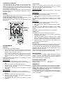
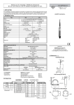
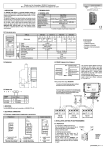
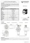
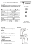
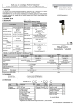
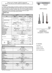
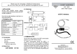
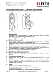
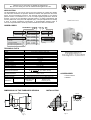
Thank you for choosing a NIVELCO instrument.
We are sure that you will be satisfied throughout its use.
APPLICATION
The NIVOPRESS NT-100 can be used for the level metering of masses and liquids.
The instrument measures the pressure difference between the liquid head above the
sensor and the atmospheric pressure. The electrical signal provided by the ceramic
pressure sensor is converted into a 4 to 20 mA output signal proportional to the level
changes. The use of the capacitance principle results in a stable measurement with
accuracy better than 0.2% (even with adjusted span!). The span adjustment and scaling
is done by simple pushbutton programming. A programmable damping helps to
overcome output fluctuation caused by surface turbulence and fast level fluctuation.
USER’S MANUAL
ORDER CODES
-1
-
Range
Code
0-0,1bar (max.4bar) 1
0-0,2bar (max.6bar) 2
0-0,4bar (max.6bar) 3
0-1bar (max.10bar) 4
0-2bar (max.18bar) 5
0-4bar (max.25bar) 6
0-10bar (max.40bar) 7
0-20bar (max.40bar) 8
Seal
FPM
EPDM
NIVOPRESS N
Type
Code
Transmitter
T
Transmitter/indicator B
Process connection
Code
1 1/2” BSP
1 1/2” NPT
2” Triclamp (ISO2852)
DIN 40 Pipe coupling (DIN11851)
DIN 50 Pipe coupling (DIN11851)
C
N
R
V
W
Code
1
2
Power supply
12-30 V DC
12-30 V DC/Ex *
Code
4
8
* pending
TECHNICAL DATA
Type
NT/NB-100
Range
Zero adjustment
Tum down
Overload capability (Pmax.)
Damping time
Output
Local LCD indicator
Accuracy (F.S.O.)
Temperature coeff.
Long term stability
Operating voltage (Ut)
Ex power supply
In accordance with the order code
+20 %
1:4
In accordance with the order code
0 … 10 Sec
4 to 20 mA
Scale indication from -4090 to +4090
< 0.2 %
< 0.1%/10 K
<0.15%/year
12 to 30V DC
Umax: 30 VDC, Imax: 80 mA, Pmax: 80 W
Maximum load resistance
Rt
Medium temperature
Ambient temperature
Process connection
Electric connection
wetted parts
Ut - 12V
0,02 A
(Rt ≤ 600 Ω, Ut:24V)
-30°C...+100°C
-30°C...+70°C
In accordance with the order code
2
Screw terminals for 2,5 mm via cable gland Pg16
Probe
Stainless steel Ssi 316Ti
Diaphragm seal
EPDM or Viton
Diaphragm
Ceramic (AL2O3)
Housing
Paint coated AL
IP 65
1.25 kg
Materials of
non wetted part
Mechanical protection
Weight
DIMENSIONS OF THE THREADED VERSION
Manufacturer:
Nivelco Process Control Co. Ltd.
H-1043 Budapest, Dugonics u. 11.
Phone: (36-1) 369-7575 Fax: (36-1) 369-8585
E-mail: [email protected] http://www.nivelco.hu
ACCESSORIES
1 x User’s manual
1 x Gasket
INSTALLATION
141
UNICONT
23
2
1 1/2”
83 x 102
~ 230 V
NIVOPRESS
Sw 55
4-20 mA
Pg 16
Fig. 1
Fig. 2
4-20 mA
Installation (continued)
The NIVOPRESS NT-100 transmitter is to be screwed in a stub
on the tank wall and fixed with a SW 55 open-end wrench. The
position of the stub has to be chosen so that the ceramic surface
of the transmitter should not be imposed to dynamic impact such
as jet of liquid, in-rushing medium.
The housing of the screwed in transmitter is to be positioned with
the gland looking down. The instrument is designed to allow a
turn round of 340°.
WIRING
Put the cable through the gland and connect wires in accordance
with the marking at the screw terminal. (Fig.3).
Connect the safety ground to one of the grounding screw
terminals either inside or outside of the housing.
After connecting the cables, make sure the cable gland is fixed
for tightness.
NIVOPRESS
SET
tD (s)
ZERO
Warning
LED
ON
ON
DISP
SPAN
TEST
Fig. 3
PROGRAMMING
Calibration
All devices are factory calibrated either:
•
to the nominal range of the model (in this case the 4/20 mA
values of the current output are calibrated to the nominal
pressure values, see “Order codes”) or
•
Display scaling
Scaling of the display should be done after zero and span
adjustment and start with both switches (1 and 2) in position
“ON”, then set Switch 1 to the “DISP” position
Decimal point setting
Push button “SET+” to adjust desired position of the decimal
point on the display.
ZERO Display
1. Fill the tank up to the level you wish to assign to 4 mA.
2. Set Switch 2 to the “ZERO” position.
3. Adjust value on the display by pushing the buttons “SET+”
and “SET-“.
The value set by this adjustment will appear on the display
whenever the output signal 4 mA is. Reset Switch 2 to “ON”
position.
SPAN Display
1. Fill the tank up to the level you wish to assign to 20 mA.
2. Set Switch 2 to the “SPAN” position.
3. Adjust value on the display by pushing the buttons “SET+”
and “SET-“.
The value set by this adjustment will appear on the display
whenever the output signal 20 mA is. Reset Switch 2 to “ON”
position.
End scaling of display by setting Switch 1 to “ON” position.
Damping time
The damping time can be set between 0 and 10 sec.
1. Set Switch 1 (see Fig.3) to the “tD(s)” position. This will reset
the damping time to 0 sec.
2. Increase the damping time by pressing the “SET+” pushbutton. One press, corresponds to 1 sec increase. (i.e. press
the “SET+” push-button 6 times for a damping time of 6 sec).
3. Reset the Switch 1 (see Fig.3) to the “ON” position to end
programming the damping time.
Warning LED
The ZERO point can be shifted up to +20% of the range. In case
of calibration attempt over this value, the warning LED will light.
The same way this LED will light, if the SPAN (upper level) will be
calibrated under the 25% value of the nominal range i.e. the
attempted turn down exceeds 1:4.
Should the warning LED light, both switches have to be put in
position “ON” and the adjustment should be repeated.
to the customer specified span (in this case the 4/20 mA
values of the current output are calibrated to the minimum
and maximum pressure values, specified by the customer’s
order)
Regardless of the factory calibration, the range/span can easily
be modified on site as well.
MAINTENANCE
Zero adjustment
The ZERO point can be shifted up to +20% of the range.
1. Fill the tank up to the level (pressure) you wish to assign to 4
mA.
2. Set Switch 2 (see Fig.3) to the “ZERO” position.
3. Press both “SET+” and “SET-“ push buttons simultaneously
and the 4 mA value is stored.
4. Reset Switch 2 (see Fig.3) to the “ON” position to end the
calibration.
STORAGE CONDITIONS
Span adjustment
The SPAN can be compressed to ¼ of the nominal range.
1. Fill the tank up to the (pressure) level you wish to assign to
20 mA.
2. Set Switch 2 (see Fig.3) to the “SPAN” position.
3. Press both “SET+” and “SET-“ push buttons simultaneously
and the 20 mA value is stored.
4. Reset Switch 2 (see Fig.3) to the “ON” position to end the
calibration.
The instrument does not require regular maintenance. In some
instances, however, the sensor probe may need occasional
cleaning to remove surface deposits. This must be carried out
gently, without harming the sensor probe.
Environment temperature range:
Relative humidity:
-25°C to +55°C
max. 98 %
WARRANTY
All Nivelco products are warranted free of defects in materials or
workmanship for a period of two years from the date of purchase.
Repairs under guarantee are carried out at the Manufacturer's
premises. The Purchaser is liable for costs of dismantling and
re-installation as well as transport costs.
Nivelco shall not be liable for misapplication, labour claims, direct
or consequential damage or expense arising from the installation
or use of equipment.
Nivelco Process Control Co. Ltd.
NT10G0A1
13.01.2000.