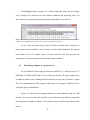
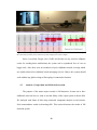
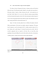
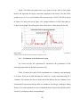
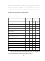
1
FALL DETECTION SYSTEM USING LOW COST COMPUTING
AND ONLINE COMMUNICATION
_______________________________________
A Thesis presented to the Faculty of the Graduate School
University of Missouri-Columbia
_______________________________________________________
In Partial Fulfillment
Of the Requirements for the Degree
Master of Science
_____________________________________________________
by
KAUSTUBH RAGHUNATH GADRE
Dr. Harry W. Tyrer, Thesis Supervisor
JULY 2012
The undersigned, appointed by the dean of the Graduate School, have examined the
thesis entitled
FALL DETECTION SYSTEM USING LOW COST COMPUTING
AND ONLINE COMMUNICATION
Presented by
Kaustubh Raghunath Gadre,
A candidate for the degree of
Master of Science
And hereby certify that, in their opinion, it is worthy of acceptance.
Dr. Harry Tyrer
Dr. Marjorie Skubic
Dr. John Fresen
ACKNOWLEDGEMENTS
I would like to take this opportunity to thank all the people who made this thesis
and my graduation in University of Missouri possible. First of all I would like to express
my sincerest gratitude to my thesis adviser, Dr. Harry W. Tyrer for his constant support,
valuable guidance, and encouragement. I would like to sincerely thank the members of
my thesis committee; Dr. Marjorie Skubic for providing very insightful comments on my
thesis and Dr. John Fresen for his valuable suggestions on statistical aspects of this
project.
I would also like to thanks all the earlier graduate students in the lab, Uday
Shriniwar, Rohan Neelgund and Krishna Kishore Devarakonda for sharing their
innovative views and helping me while learning this project. I am also thankful to my
project colleagues Karthik Peddi, Namratha Sunkara and Suriyakul Chinchao for their
valuable contribution in my work.
I am also thankful to all my iSocial project colleagues and especially Dr. Laffey
and Dr. Schmidt for showing faith all the times. My sincere appreciation is to them for
providing me a financial assistance through the most part of my graduate studies.
Last, but the most important, I owe my deepest gratitude to my parents. Without
their encouragement, faith and financial support this would not have been possible.
ii
TABLE OF CONTENTS
ACKNOWLEDGEMENTS ................................................................................................ ii
LIST OF FIGURES ............................................................................................................ v
LIST OF TABLES ........................................................................................................... viii
ABSTRACT ....................................................................................................................... ix
CHAPTER 1:
INTRODUCTION ................................................................................. 1
CHAPTER 2:
BACKGROUND STUDY ..................................................................... 4
CHAPTER 3:
METHODS ............................................................................................ 8
3.1
Initial Setup .......................................................................................................... 8
3.2
Hardware used ...................................................................................................... 9
3.2.1
Replacement of RS-232 by Universal Serial Bus (USB) interface .......................... 9
3.2.2
Replacement of desktop computer by plug computer ............................................ 10
3.3
Development environment and programs used .................................................. 11
3.4
Data acquisition and storage system .................................................................. 12
3.4.1
Conversion of carpet data in matrix format ........................................................... 12
3.4.2
Conversion of matrix carpet data in Comma Separated Value format .................. 15
3.5
Sheevaplug computer as a project server ........................................................... 16
3.5.1
Ground connection provision to Sheevaplug computer ......................................... 16
3.5.2
Domain Name System (DNS) name assignment for Sheevaplug server ............... 18
3.5.3
Transmission of carpet data to remote computer through socket Internet
connection .............................................................................................................................. 19
3.5.4
3.6
Analysis of carpet data and fall detection system .............................................. 21
3.6.1
3.7
Emergency notification for fall detection system .................................................. 20
Algorithm for fall detection system ....................................................................... 21
Development of carpet display applications ...................................................... 23
iii
3.7.1
Eclipse desktop application.................................................................................... 23
3.7.2
Eclipse web application ......................................................................................... 26
3.8
Distribution of software executable and source repository ................................ 26
3.9
Experiments........................................................................................................ 27
3.9.1
Observation of carpet data on terminal emulator ................................................... 27
3.9.2
Organization of data in files ................................................................................... 27
3.9.3
Performance of Sheevaplug computer ................................................................... 29
3.9.4
Performance of fall detection and notification system ........................................... 31
CHAPTER 4:
4.1
RESULTS ............................................................................................ 34
Data acquisition and storage system .................................................................. 34
4.1.1
Observation of data on terminal emulator using USB interface ............................ 34
4.1.2
Storing the carpet sensor data in different formats ................................................ 35
4.2
Sheevaplug computer as a project server ........................................................... 37
4.2.1
Ground connection provision to Sheevaplug computer ......................................... 38
4.2.2
Sheevaplug data conversion time and storage requirements .................................. 41
4.2.3
Accessing Sheevaplug using dynamic Domain Name System name .................... 43
4.2.4
Time for transmitting the data to the remote computer.......................................... 44
4.2.5
Displaying carpet data in the Internet browser ...................................................... 46
4.2.6
Emergency notification for fall detection system .................................................. 47
4.3
Analysis of carpet data and fall detection system .............................................. 48
4.3.1
Observation of data for largest connected component ........................................... 49
4.3.2
Performance of the fall detection system ............................................................... 50
4.4
Distribution of software executable and source repository ................................ 53
4.4.1
Smart Carpet server website .................................................................................. 53
4.4.2
Online source repository ........................................................................................ 54
CHAPTER 5:
DISCUSSIONS, CONCLUSION, AND FUTURE WORK ............... 56
REFERENCES ................................................................................................................. 60
APPENDICES .................................................................................................................. 64
APPENDIX A:
SOFTWARE USER MANUAL .......................................................... 65
iv
LIST OF FIGURES
Figure ........................................................................................................................................................ Page
Figure 3-1: Figure indicates the arrangement of carpet segments. Each segment A, B, C, D consists of 32
sensors arranged in 8 columns and 4 rows. .................................................................................................8
Figure 3-2: Figure shows the block diagram of smart carpet system. The first two blocks consists of
sensors, amplifiers and the microcontrollers system which remained same from previous implementation
[23]. The microcontroller system is connected to computer using serial to USB adapter. ....................... 10
Figure 3-3: The connection description of Sheevaplug computer. Image source:[25] .................................. 10
Figure 3-4: Figure shows the conversion of data frame into matrix format. The data is populated in 128
elements starting from ‘Start’ up to ‘End’. The 16 elements shown in lower right corner are unused and
left blank. .................................................................................................................................................. 13
Figure 3-5: The demonstration of conversion of one frame of raw data into matrix format. ........................ 14
Figure 3-6: The demonstration of conversion of one frame of matrix data into CSV format ....................... 16
Figure 3-7: Figure shows the schematic of Sheevaplug circuit board. Source: [38]. This schematic was used
analyzed to analyze the circuit board for finding the ground pin. ............................................................. 17
Figure 3-8: Figure shows the Sheevaplug circuit board with the identified ground pin encircled. The wire
connected to the ground pin establishes a ground connection with AC supply ground. ........................... 18
Figure 3-9: Block diagram describes the communication of carpet data from Sheevaplug server to the
remote computer. The data is communicated over the socket connection between the server and the
remote computer. ...................................................................................................................................... 19
Figure 3-10: Block diagram illustrates the fall situation and the notification system. Sheevaplug is
responsible for storing the carpet data, transmitting it over the Internet and notifying the fall events to the
caregiver.................................................................................................................................................... 21
Figure 3-11: Figure illustrates first two steps of the algorithm. The matrix on the left side represents data
received from microcontroller. The other matrix shows the result of step 2. ............................................ 22
Figure 3-12: Figure shows the architecture of executable eclipse application. The lower block shows the
eclipse plug-in developed for displaying the carpet data. Other blocks represent the eclipse frameworks,
operating system libraries and Java environment. .................................................................................... 23
Figure 3-13: Figure shows the architecture of executable application after its integration with the file
explorer and the terminal resources. ......................................................................................................... 25
Figure 3-14: Figure shows all the falls we performed. First row describes the Standing to falling activities.
Second row describes the Tripping and falling activities whilst the third row indicates the Sitting to
falling activities. ........................................................................................................................................ 32
Figure 3-15: Figure shows the false positive experiments performed on the carpet. We performed 11
different experiments to verify the specificity of the system .................................................................... 33
v
Figure 4-1: Data received from microcontroller, connected on USB interface is displayed on receiving
computer’s terminal emulator, appended with its timestamp .................................................................... 35
Figure 4-2: Figure shows the person fallen down on the carpet. We used this scenario for showing the
corresponding data in different formats .................................................................................................... 35
Figure 4-3: Each frame of received data is stored along with its timestamp in the separate file, created at
every one hour. The file name describes the date and time of the occurrence of the data frame. The
highlighted frame represents the data generated at the fall shown in figure 4-2. ...................................... 36
Figure 4-4: Data shown is stored in matrix format. The elements with 1 show the active sensors in the
carpet and 0 shows the inactive sensors. The crossed region represents the floor area with no carpets laid.
.................................................................................................................................................................. 36
Figure 4-5: Data shown is stored in CSV format. All 1s from the matrix are stored along with their row and
column coordinates. The highlighted row shows the CSV conversion of the matrix in Figure 4-4.......... 37
Figure 4-6: The Sheevaplug is shown connected to the microcontroller system using USB interface for
receiving the data and transmitting it over the Internet, using Ethernet connection. Sheevaplug also
performs the analysis of incoming data and notifies the caregiver after detecting the fall. ...................... 38
Figure 4-7: The Sheevaplug circuit board is shown with the ground connection provided to it. The ground
pin was identified after analyzing the circuit diagram and measuring the voltage across the pin and
ground. ...................................................................................................................................................... 39
Figure 4-8: The Sheevaplug is connected to AC power using the ground connection. This connection
achieves the common ground between both ends of RS-232 communication. ......................................... 39
Figure 4-9: Comparison of the data received by Sheevaplug before and after providing the common ground.
The upper half shows the data received before whereas the lower part shows the data received after
providing the ground connection. ............................................................................................................. 40
Figure 4-10: Number of active sensors detected by Sheevaplug before and after establishing the ground
connection. ................................................................................................................................................ 40
Figure 4-11: Graph for comparing the data conversion time v/s no. of active carpet segments .................... 42
Figure 4-12: Graph for the comparison of average memory requirement for storing the information in all
formats of data sent by microcontroller over 12 hours ............................................................................. 43
Figure 4-13: Secure shell terminal window is shown accessing the Sheevaplug server using DNS name.
The Sheevaplug can be accessed using this DNS name within the closed network. ................................. 43
Figure 4-14: Sheevaplug acting as a socket connection server and transmitting every received data frame to
the remotely connected client. .................................................................................................................. 44
Figure 4-15: Picture shows the scenario in which a person is standing on the carpet sensor making it active.
Sheevaplug is shown connected to the microcontroller circuit to receive and transmit the data over the
Internet. Remote computer is shown receiving the data and displaying it. ............................................... 45
Figure 4-16: Graph shows the comparison of the observed network latency during one hour. The line
parallel to abscissa describes the average network latency 335 ms. ......................................................... 46
Figure 4-17: Figure shows an eclipse web application opened in Internet browser on desktop computer. The
display contains 128 different blocks, each of which shows the state of one carpet sensor...................... 47
vi
Figure 4-18: The Emergency notification in the form of text message is received on nurses' mobile after
detecting the fall. The bottom part of this picture shows the way data is displayed on remote computer.48
Figure 4-19: Figure shows the matrices at two different instances of fall. Largest component is boxed and
all other smaller components are encircled. Fall notification is sent when the size of boxed component is
more than the threshold value 10. ............................................................................................................. 49
Figure 4-20: Graph for showing the variation in largest component with respect to time.The vertical line
parallel to ordinate describes the fall instane with maximum component size 10. ................................... 50
Figure 4-21: Figure shows the website of smart carpet project being hosted on the Sheevaplug server. This
website acts as the entry point of the entire software system. ................................................................... 54
Figure 4-22: Picture shows the page of project’s Google repository. This repository is developed to keep
the work secure without losing any references. ........................................................................................ 55
Figure A-1: Figure shows the launch screen of Eclipse workbench with the source code repository. .......... 65
Figure A-2: The Eclipse workbench is shown in the figure with .product file opened. The highlight areas
show the required users click while exporting an executable. .................................................................. 66
Figure A-3: Figure shows the eclipse product configuration screen before exporting. Select the parameters
as described above. ................................................................................................................................... 66
Figure A-4: The files and directories that are generated during the software creation are shown in the
Figure. Click on the SmartCarpet.exe file to launch the software. ............................................................ 67
Figure A-5: User authentication window launched after executing the application. User needs to satisfy the
authentication requirements before using the software. ............................................................................ 67
Figure A-6: Figure shows the carpet display in the software. 128 rectangles are used to represent each foil
sensor in the carpet and the remote file explorer named as ‘Carpet Data’ is used to browse the file stored
on the Sheevaplug server. ‘Start’ button is highlighted on the upper left corner. ..................................... 68
Figure A-7: Figure shows the carpet display after pressing the start button. The red color rectangles
represent the active sensors with their current activation count. ............................................................... 68
Figure A-8: Figure shows the file explorer window ‘Carpet Data’ for displaying the data files located on the
Sheevaplug server. User can right click on any .CSV file and select ‘Show History’ menu to retrieve the
data stored in the file. The terminal is also shown for invoking commands to the Sheevaplug server. .... 69
Figure A-9: Figure shows the Sheevaplug server terminal invoking the required processes. ....................... 70
vii
LIST OF TABLES
Table.......................................................................................................................................................... Page
Table 3-1: Table showing the list of Eclipse frameworks used for the development. ................................... 11
Table 4-1: Time required (ms) by a computer program to convert the data received from microcontroller
into matrix and CSV formats. First two columns describe the time for two segments while the remaining
columns describe the time for three and four segments respectively. ‘μ’ represents the mean whereas ‘σ’
represents the standard deviation of the observed times over the period of 12 hours. .............................. 41
Table 4-2: Table indicating the performance of fall detection system for fall experiments performed on the
carpet. Three types of activities are performed in each direction at 40 times. .......................................... 51
Table 4-3: Table shows the performance parameters of the system for fall experiments. The average
sensitivity was found to be very high. The false negative rate was very low. .......................................... 51
Table 4-4: Table indicating the performance of fall detection system for false positive fall experiments
performed on the carpet. Each experiment is performed twice at 10 times. Note that in this the system
detects no falls i.e. in V1 first row of 10 attempts 8 came in with no fall. ................................................ 52
Table 4-5: Table shows the performance parameters of the system for false positive fall experiments. The
average sensitivity was found to be very high. The false negative rate was very low. ............................. 53
viii
FALL DETECTION SYSTEM USING LOW COST COMPUTING
AND ONLINE COMMUNICATION
Kaustubh Raghunath Gadre
Dr. Harry W. Tyrer, Thesis Supervisor
ABSTRACT
Falls are prevalent among elderly and sometime may result in fatal injuries, which
impacts their ability of independent living. Thus, a reliable as well as cost effective fall
detection system is required. We have developed an inexpensive fall detection system,
which detects falls and automatically sends notification to the caregiver. It uses low cost,
unobtrusive wall mounted Sheevaplug computer and an Internet based free messaging
service. The fall detection solution is based on the carpet foil sensors’ information
received from the hardware support system, and uses a connected component algorithm
to discover the simultaneous activation of group of contiguous sensors during a fall. In
addition to the fall detection, the floor sensor data was stored on the Sheevaplug server
and then communicated to the remote computer using Internet socket connection. An
executable application was developed using Eclipse environment for providing a visual
representation of this data on the remote computer. A web application was further
developed by reusing the same source code. The falls algorithm was tested for 11
different fall scenarios with 4 volunteers. Experimental results show that the system is
highly reliable and accurate with the average sensitivity as 92.72 % and the average
specificity as 95.9%, for a single person. Further research on improving the floor sensor
data will also improve the results of fall detection system.
ix
CHAPTER 1: INTRODUCTION
Due to increasing life expectancy, the world population above 65 years of age
continues to increase: it was 10% in the year 2000, and is expected to be 24% by the year
2100. Likewise, the average age which was 26 years in 2000 will be 44 years by then [1].
Thus, the number of elderly people in the community is increasing and it is becoming
important to invent inexpensive technologies for helping large number of elderly live
independently, detect falls quickly, reduce the healthcare costs, and provides improved
caregiver access to elderly.
Falls are seen as one of the most dreadful events for elderly seniors, especially in
their independent living. Literature shows that 30% of independently living elderly over
65 years fall at least once every year and 30% of such falls result in disabling injuries.
Severe fall injuries can also lead to deaths [2]. Such fall events may also cause
psychological impact, that is they always feel fear of falling [3] and experience
deteriorating quality of life.
This research focuses on the development of a system to monitor ambulatory
movements of a frail elderly and send this data on the Internet using low cost wall
mounted plug computer. The online data allows relatives and caregivers to monitor the
state of the elderly seniors from the remote locations and the text messages on mobile
phones notify them about the fall incidences.
1
In this system, the elderly person does not need to carry or wear any fall detection
sensor and it’s called as passive fall detection system. It consists of low cost aluminum
foil sensors laid under a carpet to detect the presence of a person and the microcontroller
system to communicate the presence information to the computer [4]. We incorporated a
plug computer as a server to receive and store this information in two different (matrix
and CSV) formats. The use of Sheevaplug computer in place of desktop computer
reduced the cost of this system by around $1000 per installation and also made the
system less obtrusive. We established a communication between plug server and the
remote computer using Network Socket connection. The plug server was used to transmit
data to the remote computer. We also developed an Eclipse executable application for
displaying this data on the remote computer. The web application was developed with the
same set of source code, for displaying this data in Internet browsers.
For achieving fall detection, the Sheevaplug server was programmed to analyze
this data for detecting falls. The algorithm was based on the Connected Component
Labeling algorithm which is commonly used in Image processing techniques. We used an
Internet based Google Voice messaging service for reporting these falls to the caregiver.
We successfully developed and tested the fall detection system using low cost
Sheevaplug computer and the online communication. The observed results were
satisfactory in terms of sensitivity and specificity of the fall detection system. We
recorded part of the fall experiments using a video camera and then created a short video,
which is uploaded on the video sharing website YouTube.com.
2
This thesis focuses in part on the development of the inexpensive online carpet
monitoring and reporting system and the development of executable carpet display
application.
3
CHAPTER 2: BACKGROUND STUDY
Falls by elderly and the subsequent injuries are a major concern for eldercare
communities. The injuries mainly include disabling bone fractures that restrict their daily
activities and independence of living. It is observed that falls account for 40% of injury
related deaths [5], and immediate medical attention helps avoid fatalities [5-7].
Healthcare cost which includes medication, diagnostics, hospitalization, doctor visits, and
the cost of care giver can be very expensive [5]. Fall detection of the elderly is important
reducing the mortality as well as the considerable expenditure in healthcare [8].
Many researchers have worked on fall detection systems. Accelerometer based
wearable devices for detecting falls such as waist worn mercury tilt switches [9], wrist
watches [10] mobile phones [2], hearing aids [11], and sensors placed under the armpits
[12] have been described. The disadvantages of these fall detection systems are that the
elderly person is likely to forget carrying or wearing these devices, and they may produce
false alarms. The image processing techniques [13] perform the fall detection by
analyzing the horizontal and vertical speeds during fall whereas the video based systems
[14, 15] monitors the moving objects for predicting human falls. Both these methods
violate privacy of the personnel.
University of Missouri researchers developed a video based passive fall detection
system which alleviates such privacy concern. It distinguishes human shapes from the
background by segmentation and then generating silhouette images from the video
sequences [16, 17]. Human activity modeling techniques such as graphical models,
4
Bayesian networks [18] are used to correctly identify human shapes from these images
[19]. The system neither processes nor stores the video; it only uses silhouette images
which maintain user’s privacy. In [20], a low cost Microsoft Kinect based computer
vision system was proposed to monitor elderly activity for 24-7 in low-to-no light
conditions. It uses a depth imaging technique for fall detection which is robust to the
changes in lighting and shadowing. In other work, unobtrusive vibration and sound
sensor system, in which the person does not require wearable devices, performs the fall
detection using sound that is generated during human falls [3]. A system consisting of a
circular microphone array detect falls by capturing the sound, generated during falls. It
correctly locates the source of falling sound in attempt to reduce false alarms, which also
makes the system robust under the noisy situations [21, 22].
The smart carpet system that we developed monitors the elderly senior without
any body worn device or the privacy intruding cameras. It automatically detects falls and
notifies the same using cellphone text messaging. It also consists of a server to store and
communicate the data over the Internet, to enable remote monitoring. Low cost
components produce an affordable fall detection system.
The system was originally developed containing 4 carpet segments, each
consisting of 4x8 aluminum foil sensors to detect the person’s presence standing on it.
The microcontroller selects the amplifier output, connected to foil sensors and sends it to
the display computer [4]. A specific protocol was used for sending the floor sensor data
in continuous stream of characters [23]. This system was developed to detect the presence
of a person and display the information of sensors on a local computer [24]. It was not
equipped to store and produce it on the Internet or to detect any falls. This necessitated a
5
server that detects falls and makes the data available on Internet at all time. The server
needed to be cost and power efficient. Also, we needed the software executable for
displaying movement on the carpet.
Global Scale Technologies manufactures the wall mounted plug computer called
the Sheevaplug. As the name suggests, it can be directly hooked onto the AC power on
the wall used without any display monitor or I/O device. It is available in different
versions having different technical specification and costs. We used the Sheevaplug being
one of the first and cheapest among its variants GuruPlug, DreamPlug and D2Plug. It
fulfilled all the requirements to be the Smart Carpet server such as data acquisition,
storage, and communication over the Internet [25].
The network sockets were used for transmitting the data from Sheevaplug server
to the remote computer, and Java programs were developed for both ends of
communication. The network socket is a direct connection between two processes that
are running on two different computers. The data acquired on the Sheevaplug was
forwarded to the remote computer over this connection [26, 27].
Eclipse development environment v3.5 was used for exhibiting the data received
on the remote computer through the socket connection. Eclipse started as an IBM project
and then became an open source software development environment. Its functionality is
divided into plug-ins that are mainly written in Java. Users can customize the existing
plug-ins or can add new one for the additional functionality. We developed a new plug-in
containing the carpet display and then created an executable file using the base Eclipse
environment [28].
6
For developing the fall detection algorithm, we began with graduate student
discussions who led us to number of image processing algorithms. The Connected
Component Labeling algorithm was found suitable as it process the pixelated image,
which is in the matrix format. We had envisioned storing the carpet data in a matrix
format and hence developed the fall detection algorithm based on connected component
labeling [29].
7
CHAPTER 3: METHODS
We developed a smart carpet to detect falls by frail elderly. The system has
largely been built and this work includes the data reading, storage, display and
communication. First, we discuss recording the person’s movement and storing the floor
sensor data. Then focus on using Sheevaplug, a low cost computer, for data storage and
communication. We also developed algorithm for fall detection, alert signal generation,
and display application.
3.1 Initial Setup
The smart carpet system is made of four carpet segments arranged as shown in
Figure 3-1.
Figure 3-1: Figure indicates the arrangement of carpet segments. Each segment A, B, C, D consists of 32 sensors
arranged in 8 columns and 4 rows.
Each segment having 4x8 foil sensors is connected to a circuit of 32 operational
amplifiers and a microcontroller. Such 4 segments along with their microcontrollers
comprise the complete hardware system for covering the entire room. Only one
8
microcontroller is connected to the computer using a cable having Recommended
Standard-232 (RS-232) serial connectors on both ends. All the microcontrollers
communicate with each other using wireless protocol [23].
The software system acquires the floor sensors data and displays it on a personal
computer [24]. It displays the state of sensors and the way person walks on it. We
identified enhancements for this system as goals for our project, which includes storing
and communicating the data over the Internet, detecting and notifying the fall events and
implementing the above features using plug computers. Following sections discusses the
methods carried out to achieve these goals.
3.2 Hardware used
3.2.1
Replacement of RS-232 by Universal Serial Bus (USB) interface
In the earlier implementation of this system, a connection between the
microcontroller and the personal computer was established using RS-232 because it takes
only 4 pins of microcontroller and it was a most commonly used communication
interface [23]. However, the new cheap wall-plug mounted computers like Sheevaplug do
not commonly provide RS-232, but do accept USB communication interface. We chose
Prolific’s PL 2303 Serial to USB converter kit [30] to establish connection between the
microcontroller and personal computer. This replaced the RS-232 connector on
computer’s end with USB, leaving the transmitting end connector as RS-232 (Figure
3-2). The instructions and the device drivers for this adapter are available for download
for free from prolific website [30].
9
Sensors and
Amplifiers
Micro-controller
System
Prolific Serial to
USB adapter
RS-232
Connection
USB
Connection
Figure 3-2: Figure shows the block diagram of smart carpet system. The first two blocks consists of sensors, amplifiers
and the microcontrollers system which remained same from previous implementation [23]. The microcontroller system
is connected to computer using serial to USB adapter.
3.2.2
Replacement of desktop computer by plug computer
We required a low cost, low power consuming computer to be used for
continuous data collection which will also fit in very small space. Wall plug computers
fulfill the above requirements. We chose Marvell’s Sheevaplug computer which provides
a USB 2.0 port for connecting a communication cable from the microcontroller, Secure
Digital (SD) card reader for extending the memory and gigabit Ethernet for high speed
wired Internet connectivity. The plug computer is physically small with dimensions
110mm (L) x 69.5mm (W) x 48.5mm (L) [25], which can be installed at a site near the
smart carpet system. It is available for $100 that is way cheaper compared to the desktop
computers. Figure 3-3 shows the description of Sheevaplug connection ports.
Figure 3-3: The connection description of Sheevaplug computer. Image source:[25]
10
3.3 Development environment and programs used
For the software development part of this project, we considered our experience
and used Eclipse v3.5 Galileo development environment [28]. Eclipse environment is a
collection of plug-ins and frameworks. The Plug-ins are developed separately by software
engineers to add new functionality into the environment whereas the framework is a
collection of plug-ins that are grouped together by the functionality they provide. We
developed one such plug-in by using following Eclipse Frameworks that are developed
by Eclipse Foundation, an open source community and made available for use at no cost.
Table 3-1: Table showing the list of Eclipse frameworks used for the development.
Eclipse Framework used
Purpose of use
Standard Widget Toolkit (SWT) [31]
Displaying the sensors’ activation on computer
Rich Ajax Protocol (RAP) [32]
Displaying the sensors’ activation in Internet browser
Remote System Explorer (RSE) [33]
Remotely Accessing the carpet data, stored on
Sheevaplug server
Rich Client Protocol (RCP) [34]
Creating a software executable containing all the above
plug-ins, development environment, our computer
programs
In the earlier implementation, a Windows utility, Hyper Terminal was used for
observing the floor sensor data, arriving on the computer. However, this utility was not
available in Windows 7 and hence we used another similar utility, SecureCRT. It is
available to download for free on the manufacturer (VanDyke) website [35].
For converting and then storing the carpet data in Comma Separated Value (CSV)
format, an openCSV program library was used. It is developed by the another open source
community and is also available to download for free [36].
11
3.4 Data acquisition and storage system
The micro-controller scans all the sensors in carpet segments A, B, C, and D. It
compiles a frame of data starting with word S (start) followed by the data for segments A,
B, C, and D and ending with word E (end) [4]. It continuously sends these frames to
computer at a speed of 19.2 kbps [23]. For acquiring this data on computer, we
established the connections as shown in Figure 3-2 and displayed the data [24]. However,
we required data in different formats for its further analysis, storage and display. This
section discusses the details of conversion and storage techniques in two different
formats. The matrix shows each data scan in the same form as the sensor layout on the
floor providing positional information. The second format, Comma Separated Value
(CSV), takes the advantage of sparse nature of the data and reduces the frame size.
3.4.1
Conversion of carpet data in matrix format
Each frame of data contains 32 HEX digits representing the floor sensor data for
four carpet segments, each having 32 sensors. For example: if a received data frame is
SA80000000B00000000C00000000D00000000E, then first digit in A (8H, 10002)
informs the activation of first sensor in segment A but all others inactivated. The entire
frame shows the activation information of all 4 32 sensor segments i.e. 128 sensors in the
system. This raw data format is very efficient for transmission however; it’s difficult to
correctly locate the person on the carpet. Hence, we developed the computer program to
convert this data in the matrix format. We chose the matrix size as 12x12 having 144
elements to accommodate the data for 128 sensors, and the 16 blank sensor spaces.
12
Figure 3-4 demonstrates the conversion of frame into matrix format. The
computer uses the data between S and E to fill the matrix as shown. It starts from ‘start’
and continues filling up the elements up to ‘end’.
Algorithm for converting the data frame into matrix format:
1. Read one frame of data sent by microcontroller. Convert the HEX data for A, B,
and C into binary format.
2. Store 96 binary digits (32 for each segment) in matrix at co-ordinates starting
from (0, 0) to (7, 11).
3. Convert HEX data for D into binary format and store remaining 32 binary digits
in matrix at co-ordinates from (11, 0) to (7, 0) as shown in fig 3-4.
4. Store the entire matrix in file month_dd_yy_hours_MATRIX.txt.
Go to step 1.
(0, 0)
Start
(0, 11)
(7, 0)
End
(7,z 11)
(11, 0)
(11, 11)
Figure 3-4: Figure shows the conversion of data frame into matrix format. The data is populated in 128 elements
starting from ‘Start’ up to ‘End’. The 16 elements shown in lower right corner are unused and left blank.
13
For
Example:
the
binary
data
for
every
segment
in
the
frame
SA81000000B00000080C00000080D81000000E is:
Segment A:
10000001
00000000
00000000
000000002
Segment B:
00000000
00000000
00000000
100000002
Segment C:
00000000
00000000
00000000
100000002
Segment D:
10000000
00000000
00000000
000000002
Figure 3-5: The demonstration of conversion of one frame of raw data into matrix format.
Hence, the matrix format clearly shows the position of active sensors in the room
and in turn helps identifying the person’s location on it. However, the matrix may contain
large number of zeros representing the inactive sensors. Such matrices are called as
sparse matrices and are very inefficient to store. In order to achieve memory efficiency,
we needed to eliminate all unnecessary 0s and decided to store only 1s along with their
matrix coordinates. Next sections describe the storing technique of sparse matrices in
memory efficient and user readable format.
14
3.4.2
Conversion of matrix carpet data in Comma Separated Value format
A CSV format is an efficient format for storing tabular or matrix data. It stores the
data in a single line in which each datum separated by commas. Because of sparse nature
of the data we store only the co-ordinates of the 1s in the matrix as the records. We
developed a program to search the co-ordinates of 1s in horizontal raster scan then create
a single line of all these 1s records by separating them using commas. The pseudo code is
described as follows:
1. Let matrix row be r and column be c. Let result_list be the list to store the co-
ordinates. Set r =0 and c = 0. Start reading matrix elements at (r, c).
2. If the value at (r, c) = 1 then store the r, c co-ordinates in the result_list. If r = 11
and c =11 then go to step 4.
3. If c < 11 then increment c by 1 and go to step 2. Else, increment r by 1, set c = 0
and go to step 2.
4. Transform the result_list into comma separated value line using openCSV library
[36] and store it in month_dd_yy_hours.csv
We will use the matrix from Figure 3-5 for the demonstration. The co-ordinates of
1s in the matrix are (0, 0), (0, 7), (0, 11), (7, 0), (11, 0). We defined the following CSV
format for these co-ordinates.
“1(0, 0)”, “1(0, 7)”, “1(0, 11)”, “1(7, 0)”, “1(11, 0)”, “Mar 1, 2012 4:19:22 PM”
Figure 3-6 demonstrates the conversion of matrix data in a line of CSV format.
15
(0, 0)
(0, 11)
(11, 11)
(11, 0)
“1(0, 0)”, “1(0, 7)”, “1(0, 11)”, “1(7, 0)”, “1(11, 0)”, “Mar 1, 2012 4:19:22 PM”
Figure 3-6: The demonstration of conversion of one frame of matrix data into CSV format
3.5 Sheevaplug computer as a project server
The data acquisition and storage system was intended to operate for 24x7 to
collect all the movements happening on the carpet. In such applications, we may not
always need the full-fledged desktop computer. Those are costly as well as they consume
lot of power and occupy lot of space. Hence, we replaced our desktop computer by the
plug computer. The plug computer is equipped with minimal resources, but sufficient for
executing our computer programs. This section discusses the detail procedures for setting
up the project server on Sheevaplug computer.
3.5.1
Ground connection provision to Sheevaplug computer
We used the Sheevaplug computer to service the data acquisition system and
observed large number of invalid characters in the form of noise. The similar noise was
observed on laptop computer when operating on batteries. We excluded noise on the
desktop computer, and the available documentation [4, 23, 24] of this project did not
mention how to resolve this issue.
16
Now RS-232 communications requires both ends at zero volts for communication
[37]. The Sheevaplug computer does not have a ground connection so that the RS-232
receiving end was left ungrounded. This requires grounding of the Sheevaplug signal
side. To address this issue, we analyzed the Sheevaplug circuit board with the help of its
layout shown in Figure 3-7.
Figure 3-7: Figure shows the schematic of Sheevaplug circuit board. Source: [38]. This schematic was used analyzed
to analyze the circuit board for finding the ground pin.
The major steps are as follows:
1. The layout shows few ground pins. We measured voltage between each pin
and the ground from the microcontroller system because both of them use a
power supply from the same connection.
2. When this voltage was found to be zero, we identified one pin as ground
which was suitable for making a wired connection to AC supply ground
(Figure 3-8).
3. This established common ground between the microcontroller and the
Sheevaplug computer.
17
Figure 3-8: Figure shows the Sheevaplug circuit board with the identified ground pin encircled. The wire connected to
the ground pin establishes a ground connection with AC supply ground.
Next, in order to remotely monitor movements on the carpet, we decided to make
this data available on the Internet. The next two sections discuss the steps taken for
communicating the data over the Internet.
3.5.2
Domain Name System (DNS) name assignment for Sheevaplug server
To access any server on the Internet it must have a DNS name assigned to it. We
assigned a DNS name to the Sheevaplug server for making it available in the network
with a project related name, using dyndns.com facility. The ‘carpetsmart.dyndnsserver.com’ name will be used in all further sections. The detail directions for using the
DynDNS are provided at Ubuntu official documentation [39].
18
3.5.3
Transmission of carpet data to remote computer through socket Internet
connection
To remotely monitor movements on the carpet, it was necessary to communicate
the data to the remote computer. We established a TCP socket connection between the
remote computer and the Sheevaplug server as shown in Figure 3-9.
http://carpetsmart.dyndns-server.com
Micro-controller
System
Sensors and
Amplifiers
SA00210000B…..E, 384177024645945
Internet
ACK, 384177024645945
Sheevaplug server acquiring
and transmitting the carpet
data to the remote computer
through socket Internet
connection
Figure 3-9: Block diagram describes the communication of carpet data from Sheevaplug server to the remote
computer. The data is communicated over the socket connection between the server and the remote computer.
The algorithm for establishing socket connection server on Sheevaplug server:
1. Initiate the socket connection on port 99999.
2. Check for any incoming client connection request. If request found, make
a connection to the client and store its IP address.
3. Acquire one line of carpet data from the data acquisition system. Organize
the frame of data by appending the time of occurrence. Transmit the frame
to the connected clients.
4. Receive an acknowledgement from each client.
5. Go to step 2.
The algorithm for socket connection client on remote computer:
1. Request a socket connection to the server at address described in Figure
3-9 on the port number 99999. Wait for server to accept the connection.
19
2. Receive a complete frame of data from S to E. Send back an
acknowledgement ACK to the server.
3. Display data locally on the eclipse application display.
4. Go to step 2.
3.5.4
Emergency notification for fall detection system
Google Voice offers a free Internet based telephone service for sending text
messages and placing calls, by assigning a separate phone number to every Google
account holder. We created a Google account and obtained a phone number. Google
Voice also provides a Java library [40] for integrating its telephone service in the user
program. Using this library, we developed a text message notification system for
declaring fall events. We also defined different text recipient numbers based on the
caregivers’ schedules, in the external properties file stored in Sheevaplug. The algorithm
of the notification system is as follows, and operates in the Sheevaplug.
1. Initiate a connection to the Google voice server using the phone number.
2. Check if there is any fall declared by the fall detection algorithm.
3. If fall is detected, select recipient’s phone number from properties file for the fall
time. Send the notification text to the selected number, wait for 45 seconds.
4. Go to step 2.
Since, the microcontroller sends data at a rate higher than the person’s walking
speed, the fall detection system could declare multiple falls for a single physical fall. To
prevent this, we decided to suspend the notification system for next 45 seconds. Figure
3-10 illustrates the fall detection system.
20
Amplifier and
Microcontroller
system
Sheevaplug
Server
Internet
Figure 3-10: Block diagram illustrates the fall situation and the notification system. Sheevaplug is responsible for
storing the carpet data, transmitting it over the Internet and notifying the fall events to the caregiver.
3.6 Analysis of carpet data and fall detection system
Floor sensors and the microcontroller system used in the carpet are intended to
sense the person’s presence. In addition, matrix formatted data provides the location of a
person. However, none of those help knowing the individual’s state i.e. standing, sitting,
or lying. Hence, it is difficult to identify if there is a fall on the carpet. We designed an
algorithm for detecting falls by manipulating each matrix and comparing it with
preceding ones.
3.6.1
Algorithm for fall detection system
In order to estimate the design parameters of the algorithm, we performed
intentional falls on the carpet with the help of volunteers. After carefully observing the
recorded data, we found that person in a fallen state occupies a region of approx. 10
connected sensors with a change of nearly 6 sensors from the previous frame of data. The
numbers 6 and 10 were selected as thresholds in the algorithm.
The following describes the major steps in the algorithm:
21
1. Read one frame of data from the microcontroller and convert in the matrix format.
2. Scan the matrix in a horizontal raster scan and call the current element as pivot
element.
3. If the pivot element is ‘1’, then check the value of all 8 neighboring elements.
a. If at least one neighbor is found 1, then make the pivot 2.
b. If all neighbors are 0, then retain the value of pivot element.
4. If the size of largest region occupied by contiguous 2s 10 or greater, then compare
it with the size of previous frame.
a. If the difference is higher than 6, send an alert to the notification system.
5. Go to step 1.
Figure 3-11: Figure illustrates first two steps of the algorithm. The matrix on the left side represents data received from
microcontroller. The other matrix shows the result of step 2.
Figure 3-11 illustrates the data produced during steps 1 and 2 in the above
algorithm. The first matrix is similar to the one shown in Figure 3-5 i.e. containing only
0s and 1s. In second step, every pivot of ‘1’ which is connected to any other ‘1’ is
replaced by 2, as shown in second matrix. The matrix sub regions with neighboring 2s are
identified in next step. In short, the algorithm declares a fall occurs when the size of
22
largest contiguous sub region is found to be 10 or larger and exceeds the previous frame
by 6 such contiguous elements.
3.7 Development of carpet display applications
For displaying the carpet data on Graphical User Interface (GUI), we developed
two display applications: one for displaying it on the computer and the other for Internet
browsers. This section discusses the steps of development of the applications.
3.7.1 Eclipse desktop application
We developed an executable application (.exe) to monitor the carpet data received
from the Sheevaplug on a remote computer display. Figure 3-12 shows the architecture of
this application. The entire .exe file consists of parts from the Frameworks: Standard
Widget Toolkit (SWT), Remote System Explorer (RSE), core Eclipse environment, and
the other necessary parts. These parts are the Operating System libraries and Java
Runtime. The shaded block represents the carpet display and the file explorer window
that we developed as a plug-in. We used the Rich Client Platform (RCP) framework to
create a single executable file from the plug-in and the framework codes.
Java Runtime
Environment
Operating
System
Eclipse Core
SWT
RSE
Eclipse plug-in
Figure 3-12: Figure shows the architecture of executable eclipse application. The lower block shows the eclipse plugin developed for displaying the carpet data. Other blocks represent the eclipse frameworks, operating system libraries
and Java environment.
23
3.7.1.1 Development of carpet display
Using a socket client program, remote computer receives data from the
Sheevaplug server. To show this data, we developed the display containing 128
rectangles. Each rectangle corresponds to one floor sensor. The color of each rectangle
changes with state of a sensor i.e. red if active otherwise, green. The following operations
are performed while displaying the data:
1. The remote client activates the socket connection to the Sheevaplug server. Once
connected, the client starts polling for new available data.
2. If new data is available, the client converts it into matrix format as discussed in
section 3.4.1.
3. For every matrix element:
a. If found 1, then make the rectangle red.
b. If found 0, then leave the block green.
4. Go to step 2.
3.7.1.2 Integration of file explorer and the terminal window in the carpet display
RSE framework provides the file explorer and the terminal resources to allow
users to browse the files located on the server and observe the data coming from the floor
sensors. Figure 3-13 shows the architecture of the system after integration of these
resources. It shows that the carpet display, the file explorer and the terminal are given an
access to the remote server through network interfaces: computer’s hardware interface
and the network interface libraries. The interface libraries provide an access based on the
server’s Operating System.
24
Carpet Display
File
Explorer /
Terminal
RSE Network Interface Libraries
Computer Network Interface
Internet Tunnel
Remote Server
(Linux, Windows, FTP, SSH, Telnet)
Figure 3-13: Figure shows the architecture of executable application after its integration with the file explorer and the
terminal resources.
The idea behind adding the file explorer was to provide an ability to select and
‘play’ the previous carpet data on the same display. To perform this, user need to open
the server connection in the explorer window and then click on ‘Show History’ after
selecting an appropriate file.
The following is the algorithm for displaying the data stored in a file:
1. Read new line of data from the file. Truncate the timestamp from it.
2. Convert back the line of CSV data into matrix form by reversing the procedure
discussed in section 3.4.2.
3. Iteratively check the value of every matrix element:
a. If found 1, then change the block color to red.
b. If found 0, then change the block color to green.
4. Check if the end of file is reached.
a. If yes, go to step 6.
b. If no, go to step 1.
5. Stop.
25
3.7.2 Eclipse web application
We already discussed about using Sheevaplug as a ceaselessly running server to
acquire the microcontroller data and to notify the emergency situations after detecting
falls. We went ahead to make it a web server for displaying the carpet data in Internet
browser.
Among various web development techniques, Rich Ajax Protocol (RAP) was
found to be most useful, especially after having a carpet display developed for showing
data on the computer. RAP creates a web application by reusing the code developed
during carpet display with the addition of RAP Widget Toolkit (RWT). RWT basically
transforms the entire SWT display components for displaying in the browsers. This way
we developed two different display applications with the single development effort.
3.8 Distribution of software executable and source repository
For the distribution of executable file, we developed a separate project webpage
using HTML and hosted on the Sheevaplug server. The website contained the project
outline information, the information of all team members and the software download
section for downloading an executable file.
We also created an online code repository in the Google cloud for backup. Future
graduate students can use this code repository to continue working on this project.
26
3.9 Experiments
We carried out experiments to determine the performance of the Sheevaplug
computer and the system’s fall detection ability. The experimental setup contained 4
carpet segments each with 32 foil sensors with amplifier and microcontroller systems [4].
We tested the Sheevaplug server and a remote computer display. Importantly, we tested
the system’s ability to detect falls. We walked on the carpet and the data was recorded on
the server and observed on the remote computer. With each footstep, the display was
expected to change accordingly, with a fall on the carpet; a mobile phone was expected to
receive a notification. The experiments were categorized as follows.
3.9.1
Observation of carpet data on terminal emulator
This experiment was meant to verify if the USB connection produces the same
data as observed with RS-232 connection. We produced the data by walking on all 4
carpet segments. The system was setup as shown in Figure 3-2 and the data was observed
on SecureCRT terminal window.
3.9.2
Organization of data in files
The experiment was carried out to store the data in three different formats (raw
data, matrix format, CSV format). Sheevaplug server was connected to microcontroller
using RS-232 to USB adapter (Figure 3-2). We acquired the data during day time by
walking and falling on the carpet as well as by leaving the system idle in the night. These
activities were individually performed by the graduate students in the lab. For every hour
of data acquisition, the program created three different files with the three formats (raw
27
data, matrix, CSV). The system was setup to generate the data for 4 weeks and continued
running for that time.
3.9.2.1 Observation of data conversion time
A computer program was developed to calculate the data conversion time. It
performs following steps: note the time of new frame as t1, the time when matrix and
CSV formats became available as t2 and t3, calculate the differences (t2 - t1) and (t3 - t2)
and store them in separate file. We recorded the times when 2, 3, and 4 carpet segments
were used. In future, the system will use more number of carpet segments, it is important
to calculate the data conversion times.
3.9.2.2 Observation of memory required for storing the data
Using our hourly generated files in three formats, we selected a time length of 12
hours (10 AM – 10 PM) and obtained the 36 generated data files, as discussed in 3.9.2.
The files were selected to include walking, falling and idle time for the carpet. We
calculated the average size per hour for raw data files, matrix data files, and CSV data
files. Future implementation will require compensation for variable number of sensors in
one room, since the raw data and the matrix sizes will also vary. The expected file size
impacts the data sampling and storage rate.
28
3.9.3
Performance of Sheevaplug computer
3.9.3.1 Verification of Sheevaplug ground connection
This experiment aimed to verify the ground connection which was intended to
achieve common ground between both connectors of RS-232 communication cable i.e.
the microcontroller and Sheevaplug server. We used the same experimental setup
previously discussed and shown in Figure 3-2. The test was carried out by connecting and
then disconnecting the ground connection, the SecureCRT terminal was expected was
used to see the difference in carpet data: when ungrounded the expected data should be
noisy whereas the correct sensor data was expected in ground connected state.
3.9.3.2 Verification of Sheevaplug access using DNS name
The purpose of this experiment was to determine that we could access the
Sheevaplug from a remote computer using the DNS name. We followed the instructions
provided in the Ubuntu documentation [39] for configuring the DNS name
“carpetsmart.dyndns-server.com” to Sheevaplug server. The DNS was configured to
access the server using its domain name rather than remembering its IP address. ssh
command was used to login into the server from remote computer using SecureCRT
terminal.
Command used: ssh [email protected]
The terminal window allows access to the server after satisfying user
authentication requirements. We repeated this experiment from different wireless and
29
wired Internet access points in the same network. We also performed the experiment
from the outside access points.
3.9.3.3 Observation of data on a remote computer
A remote computer was used for receiving the data from Sheevaplug server over
the socket Internet connection. We used two different programs for establishing this
connection. A server program was used to transmit the data and a client program was
used to receive it. We performed an experiment by stepping on the carpet and the remote
computer was expected to receive and display the data on terminal window. We repeated
this experiment by connecting multiple computers to the Sheevaplug server.
3.9.3.4 Observation of data transmission time
A computer program was developed to calculate the expected delay while
observing the data from remote computer. We used Sheevaplug server on transmitting
side and a computer on receiving side. The program performs following steps: note t1 as
the time when a frame of data was transmitted and t2 as the time when the
acknowledgement of same frame was received. The difference (t2 – t1) was expected to
be a Round Trip Time (RTT). Hence, half of this difference was calculated as expected
delay in data. The experiment was not performed by varying the geographical distance
between the server and the computer which might increase the delay.
30
3.9.4
Performance of fall detection and notification system
We conducted the experiments to determine the Sensitivity, Specificity, False
Negative Rate (FNR), and the False Positive Rate (FPR) of the fall detection system. The
Sheevaplug server was used to detect and declare the falls and a mobile phone was used
as a medium to notify the event. We performed following experiments based on the falls
test protocol [41].
3.9.4.1 Sensitivity analysis of the fall detection system
The fall experiments were carried out with 4 volunteers, each performing every
experiment for 10 times as shown in Figure 3-14. Hence, the total numbers of trials were
440.
In every experiment, when volunteer fell on the carpet the mobile phone was
expected to receive a notification message. If the notification was received, it shows that
the trial was detected as fall and we noted it as true positive. On the other hand if the
notification was not received, it shows that the system failed to detect the fall, and we
noted it as false negative. The Sensitivity and the FNR were calculated using the number
of detected falls and the number of non-detected falls respectively. The average FNR and
the average sensitivity were calculated to evaluate the overall fall detection performance
of the system. Following are the formulae used:
FNR
= False Negatives / Total number of fall experiments
Sensitivity
= True Positives / Total number of fall experiments
31
1) Standing to falling
forward
2) Standing to falling
backward
3) Standing to falling to on
right side
4) Standing to falling on
left side
5) Tripping and falling
forward
6) Tripping and falling
backward
7) Tripping and falling on
right side
8) Tripping and falling on
left side
9) Sitting and falling
forward
10) Sitting and falling on
right side
11) Sitting and falling on
left side
Figure 3-14: Figure shows all the falls we performed. First row describes the Standing to falling activities. Second row
describes the Tripping and falling activities whilst the third row indicates the Sitting to falling activities.
3.9.4.2 Specificity analysis of the fall detection system
Another set of experiments were performed with the situations that are expected
to produce false positive data. Figure 3-15 shows the list of experiments we performed
with 2 volunteers, each performing every experiment at 10 times. Following are the
formulae used:
FPR
= False Positives/ Total optical false positive experiments
Specificity
= 1 – False Positive Rate
32
These experiments were not intended to produce the fall data. These were aimed
to determine the ability of fall detection system to distinguish other daily activities as non
falls. In every experiment, when volunteer performed the activity, the mobile phone was
not expected to receive any notification from the server. If the notification was received,
we noted the trial as false positive. The specificity and the FPR were calculated using
these observations.
3) Performing
1) Sitting with legs tucked
in
2) Sitting with legs
spread
5) Bend down and kneel
on floor
6) Bend down, kneel and
then lie down on floor
7) Bend down and plug an
appliance
9) Walk straight and
sudden stop
10) Walk towards chair
and sit on it
11) Sit on chair bend down
to pick book
sit-ups
4) Bend down in squatting
position
8) Bend down and tie a
shoe
Figure 3-15: Figure shows the false positive experiments performed on the carpet. We performed 11 different
experiments to verify the specificity of the system
33
CHAPTER 4: RESULTS
This software system delivers a solution that includes capturing the floor sensor
data using USB interface and storing it in various formats. The floor sensor data is
organized in frames; each frame is analyzed at real time and stored. The analysis seeks to
detect falls on the carpet to provide emergency notifications. Furthermore, the system
provides the internet based communication: it establishes the server on a plug computer
(an inexpensive wall-plug mounted computer), transmits the carpet data over the internet,
and allows access for display on the remote computer. This chapter discusses the
performance and results of all the modules in this software system.
4.1
Data acquisition and storage system
We developed a computer program to receive a continuous stream of characters
sent by the data source i.e. microcontroller. We connect the computer using a USB
interface and stored the data in user readable format such as Matrix and Comma
Separated Value (CSV) files. Every frame in the data stream is first converted into matrix
form with the same dimension as the carpet installation segments. To form the CSV
format, the matrix elements having the value ‘1’ are selected and their row and column
coordinates are then stored as described in the following sections.
4.1.1
Observation of data on terminal emulator using USB interface
We replaced the RS-232 serial communication interface which was used in earlier
implementation [23] with serial to USB adapter. This made the smart carpet system
34
compatible with new computers. Figure 4-1 shows the data received on computer’s
terminal emulator. Each line in the figure shows one frame of data. The sensors’ activation
information for segments A, B, and C is sent between S and E representing starting and ending
words respectively. The time of occurrence of each frame is appended after comma.
Figure 4-1: Data received from microcontroller, connected on USB interface is displayed on receiving computer’s
terminal emulator, appended with its timestamp
We used the USB port for further implementation of this project, in particular to
observe the data on terminal emulator (SecureCRT) and the graphical display of the
sensors (Refer APPENDIX A:). We also developed memory efficient data storing
techniques as discussed next.
4.1.2
Storing the carpet sensor data in different formats
Figure 4-2 shows the picture of a person falling on the carpet. This fall produced
the raw data frames as shown in Figure 4-3. Each frame transformed into a matrix (Figure
4-4) and each matrix reduced into a CSV file (Figure 4-5) that requires much less storage.
This section illustrates the various formats of data.
Figure 4-2: Figure shows the person fallen down on the carpet. We used this scenario for showing the corresponding
data in different formats
35
Figure 4-3: Each frame of received data is stored along with its timestamp in the separate file, created at every one
hour. The file name describes the date and time of the occurrence of the data frame. The highlighted frame represents
the data generated at the fall shown in figure 4-2.
Figure 4-4 shows the matrix format of the highlighted frame from Figure 4-3. It is
divided in 4 segments of the carpet arrangement discussed in Section 3.1. In the upper 3
segments (named A, B, C), there are 4 columns in which each column corresponds to 2
hexadecimal digits in the raw data. Similarly, in the lower segment D, there are 4 rows in
which each row corresponds to 2 hexadecimal digits. For example, the data for C and D
in Figure 4-3contains all zeros hence the matrix equivalent of them is zero. The last two
digits in A are 38H i.e. 0011 10002 which corresponds to the last column in A. Similarly,
the second two numbers in B are 15H corresponds to 0001 01012 which are mapped in
segment B 2nd column of the matrix.
Figure 4-4: Data shown is stored in matrix format. The elements with 1 show the active sensors in the carpet and 0
shows the inactive sensors. The crossed region represents the floor area with no carpets laid.
36
The highlighted frame in Figure 4-5 is achieved from the matrix shown in Figure
4-4 by storing all 1s with their row and column coordinates and neglecting all 0s. All
these formats are stored with the same timestamp which makes easy retrieval.
Figure 4-5: Data shown is stored in CSV format. All 1s from the matrix are stored along with their row and column
coordinates. The highlighted row shows the CSV conversion of the matrix in Figure 4-4.
In case of no movement on the carpet, the matrix contains all 0s. Storing such
matrix unnecessarily consumes a lot of memory; with no valid information. We ignored
such instances for CSV formats. Hence, the data stored in CSV files provides the
information of carpet movements and not the idle carpet condition.
4.2
Sheevaplug computer as a project server
We used Marvell’s Sheevaplug with Feroceon 88FR131 1.2 GHz processor, 512
MB RAM, 512 MB NAND Flash to receive and store the data. The plug computers are
available in market at price starting from $100 and they occupy space less than ½ square
foot. The implementation of this computer reduces the cost by approx. $1000 as well as
saving the space per installation.
Figure 4-6 shows the Sheevaplug connected to microcontroller using the USB
interface. It receives the data and transmits over the internet using Ethernet connection
allowing remote computer to display. We used this setup for further experiments in this
project.
37
Figure 4-6: The Sheevaplug is shown connected to the microcontroller system using USB interface for receiving the
data and transmitting it over the Internet, using Ethernet connection. Sheevaplug also performs the analysis of incoming
data and notifies the caregiver after detecting the fall.
4.2.1
Ground connection provision to Sheevaplug computer
The connection from the final microcontroller to the Sheevaplug begins with a
wire with an RS-232 connection (grounded) then a USB connection (ungrounded) to the
Sheevaplug. That is the Sheevaplug is not grounded to the microcontroller system and
produces invalid characters as a data (see Figure 4-9, Figure 4-10). While it was clear this
was a grounding problem, its resolution was not easily forthcoming.
Discussions with the manufacturer were helpful but not conclusive. We ended up
analyzing the Sheevaplug circuit and circuit board to find a suitable ground pin. Figure
4-7 shows the Sheevaplug circuit board with its identified ground pin and connected this
pin to the AC supply ground as shown in Figure 4-8.
38
Figure 4-7: The Sheevaplug circuit board is shown with the ground connection provided to it. The ground pin was
identified after analyzing the circuit diagram and measuring the voltage across the pin and ground.
Figure 4-8: The Sheevaplug is connected to AC power using the ground connection. This connection achieves the
common ground between both ends of RS-232 communication.
To prove the assertion that grounding was required, we performed an experiment
connecting and then disconnecting the ground connection and observed the difference in
the received data. Figure 4-9 shows this difference in the data. The upper half of Figure
4-9 shows the Sheevaplug terminal showing sensor data corrupted by noise due to lack of
common ground, while the lower half shows the correct data sent by microcontroller. In
the latter case, the values were zero for all non-active sensors except the 2nd sensor in last
column of B which had been activated.
39
Figure 4-9: Comparison of the data received by Sheevaplug before and after providing the common ground. The upper
half shows the data received before whereas the lower part shows the data received after providing the ground
connection.
Figure 4-10 shows the graph where each point shows the number of active sensors
in each line of raw data in Figure 4-9. These sensors were detected by Sheevaplug before
and after connecting the ground pin. The ground pin eliminated the large amount of
invalid data.
Figure 4-10: Number of active sensors detected by Sheevaplug before and after establishing the ground connection.
40
4.2.2
Sheevaplug data conversion time and storage requirements
It’s important to analyze the time and memory requirements of Sheevaplug in the
process of real time data acquisition. We measured the data conversion times and storage
requirements for each storage format using the Sheevaplug on receiving end.
We calculated the difference between the times at which the raw data frame
arrived at computer and the time at which the new format became available, obtained
mean and standard deviation of these differences are shown in Table 4-1. The mean and
standard deviation of the conversion times was over a 12 hours period. In the table, the
first two columns describe the times when two segments were used, whereas the
remaining columns describe the times when three and four segments were used
respectively.
Table 4-1: Time required (ms) by a computer program to convert the data received from microcontroller into matrix
and CSV formats. First two columns describe the time for two segments while the remaining columns describe the time
for three and four segments respectively. ‘μ’ represents the mean whereas ‘σ’ represents the standard deviation of the
observed times over the period of 12 hours.
Conversion Times (ms)
For 2 installation segments
For 3 installation segments
For 4 installation segments
For Matrix
Format
For CSV
Format
For Matrix
Format
For CSV
Format
For Matrix
Format
For CSV
Format
μ = 15.158
σ = 1.407
μ = 16.842
σ = 2.398
μ = 16.056
σ = 1.847
μ = 17.648
σ = 1.959
μ = 16.195
σ = 2.752
μ = 18.091
σ = 2.83
Each frame of microcontroller data arrived on Sheevaplug every 130-140 ms. The
conversion times in Table 4-1 are substantially less than this so the system can convert
and store every line of received data. Figure 4-11 shows a graph of some conversion
times. It is clear from Figure 4-11 and Table 4-1, the conversion time increases slightly in
direct proportion to the number of active segments. Hence, in order to occupy larger
41
rooms, more number of segments can be used. The conversion time limit will need to be
assessed for substantially larger rooms.
Conversion Time (ms)
25
Comparison of data conversion times
20
15
For Matrix & CSV
format
10
For matrix format
5
0
222222222233333333334444444444
Number of active segments
Figure 4-11: Graph for comparing the data conversion time v/s no. of active carpet segments
We stored each line of data in three formats and compared storage requirements.
We obtained data under two different activities i.e. idle carpet condition and moderate or
busy walking. In the idle condition, no active data was generated so we stored it only in
the raw data and its matrix equivalent (the CSV format was null). In a walking activity,
all three formats were stored; the raw and matrix formats required the same space for all
activities while the CSV file size grew depending upon the number of active sensors.
Figure 4-12 shows the average memory requirements calculated over 12 hours of data
acquisition: clearly CSV storing technique is very memory efficient whereas matrix and
raw data formats occupy a lot of space. It is convenient to extract a person’s movement
from the CSV format, since it stores only active sensor’s data (refer Figure 4-5). Matrix
format, being inefficient in terms of memory, simplifies reading and identification of
person’s location on the carpet. Hence, matrix and CSV can said to be a tradeoff between
memory usage and ease of locating the person.
42
Memory required to store
(KBytes)
16000
14000
12000
10000
8000
6000
4000
2000
0
Comparison of memory requirements of
data storage techniques
13872 13872
No Activity
1417 1417
0
936
Raw Frame
Matrix Format
CSV Format
Format Format of stored data
Figure 4-12: Graph for the comparison of average memory requirement for storing the information in all formats of
data sent by microcontroller over 12 hours
4.2.3
Accessing Sheevaplug using dynamic Domain Name System name
We assigned a dynamic DNS name to Sheevaplug server for providing easy
access to it from any computer in the network. Figure 4-13 shows the terminal window
used while logging into the DNS enabled Sheevaplug server.
Figure 4-13: Secure shell terminal window is shown accessing the Sheevaplug server using DNS name. The
Sheevaplug can be accessed using this DNS name within the closed network.
We successfully accessed the server using DNS name at various locations in the
University network including the wired and wireless access points. Due to the limitations
from University network administration, we could not make this server accessible outside
43
the MU network. Assignment of static IP or the DNS name within missouri.edu can make
this happen.
4.2.4
Time for transmitting the data to the remote computer
Figure 4-14 shows the terminal window on a remote computer. It displays data
received from Sheevaplug, which receives the data from the microcontroller. We used
one computer having an IP address 10.7.62.28 for receiving this data over the Internet.
Figure 4-14: Sheevaplug acting as a socket connection server and transmitting every received data frame to the
remotely connected client.
Figure 4-15 shows the scenario for acquiring the data shown in Figure 4-14. The
carpet data is displayed on the remote computer without any wired connection to the
microcontroller or the Sheevaplug server. It receives the data through the socket Internet
connection to the server. The Sheevaplug server transmits every frame of data and places
a time of occurrence at the end of the data frame.
44
Figure 4-15: Picture shows the scenario in which a person is standing on the carpet sensor making it active.
Sheevaplug is shown connected to the microcontroller circuit to receive and transmit the data over the Internet. Remote
computer is shown receiving the data and displaying it.
We calculated the time elapsed for a frame to go to the remote computer.
Beginning with the time of occurrence, as described above, sent to the remote client
computer. The computer then sends an acknowledgement with the same timestamp. Upon
receiving it, the Sheevaplug server calculates the half of difference between the time of
reception of acknowledgement and transmission of the data. We used the server’s clock
time in the scale of nanoseconds for precise calculations. For example:
Transmitted frame: “SA00000000B00000000C00000000D00000000E,
384177024645945”
Received Acknowledgement: “ACK, 384177024645945” at 384177257609945
Round trip time = (384177257609945 – 384177024645945) ns
Time taken to transmit one frame
= Round trip time / 2 = 116.482 ms
45
Figure 4-16 shows the times we recorded for transmitting one frame of data to the
remote computer for one hour. It also shows the average time 335 ms which is
approximately 2.5 times the rate of data generation i.e. 140 ms. Hence, every frame
appeared to be delayed by 2 or 3 frames which can be accepted considering the added
advantage of remote monitoring. This delay is notable in displaying the fall data and the
Network Latency (ms)
actual fall.
4500
4000
3500
3000
2500
2000
1500
1000
500
0
Network latency observed in one hour duration
Time
Figure 4-16: Graph shows the comparison of the observed network latency during one hour. The line parallel to
abscissa describes the average network latency 335 ms.
4.2.5
Displaying carpet data in the Internet browser
It is important to pass the carpet data over the Internet. We installed an Apache
Tomcat web server installed on the Sheevaplug server, used an eclipse RAP for display
when opened in an Internet browser.
46
Figure 4-17: Figure shows an eclipse web application opened in Internet browser on desktop computer.
The display contains 128 different blocks, each of which shows the state of one carpet sensor.
Figure 4-17 shows a display of the smart carpet sensors demonstrating that the
eclipse web application worked satisfactorily. It also worked well on various types of
browsers running on the mobile devices and tablets (data not shown). However, being a
lightweight and tiny server, Sheevaplug took comparatively longer time to respond to
each query. To make our solution more useful, we decided to develop Internet enabled
desktop software (Refer APPENDIX A:).
4.2.6
Emergency notification for fall detection system
Figure 4-18 shows the emergency notification text received on smartphone, which
reports the situation using the predefined message format. This system is not limited to
the usage of smartphone receivers; any mobile phone can be used at the receiving end.
47
Figure 4-18: The Emergency notification in the form of text message is received on nurses' mobile after detecting the
fall. The bottom part of this picture shows the way data is displayed on remote computer.
Since we used the Google voice (VoIP) and did not use any wireless cellphone
carrier for sending these notifications, the system can be reproduced free of cost on
bigger scale. Also, there were no incidences of poor cellphone network coverage which
are usually observed in cellphone based messaging services. Hence, this system should
work without any glitch as long as Sheevaplug is connected to Internet.
4.3
Analysis of carpet data and fall detection system
The purpose of the smart carpet research is fall detection. It turns out to have
additional value but here we want to test the ability of the carpet system to detect falls.
We analyzed each frame of data using connected component analysis on each matrix.
Such connectedness results in detecting falls. This section discusses the results of fall
detection system.
48
4.3.1
Observation of data for largest connected component
We observed various fall patterns by having a volunteer perform well described
falls on the carpet. The fall patterns produce distinctive sub regions in the matrix data. A
fall pattern consists of regions of matrix elements with value 1 with connectivity size
more than 10 (Refer Figure 4-19). At every line of data, the computer program attempts
to find such connected sub regions to detect a fall. After detecting the connected region of
size 10 or more, the program declares that a fall has occurred. This information is used to
send a message notification as discussed in Section 4.2.6.
Figure 4-19 shows the data produced by two different fall patterns observed
during experimentation. Each matrix has multiple connected components. The largest
boxed component is used for detecting the fall if it exhibits connected region of 10 or
more elements with a rapid change of 6 elements from the previous matrix. Note the
encircled components; these are ignored as fall data. They are most likely other
appendages of the person falling, but can also be due either system noise or the presence
of another person etc. and the count does not reach the required threshold.
Figure 4-19: Figure shows the matrices at two different instances of fall. Largest component is boxed and all other
smaller components are encircled. Fall notification is sent when the size of boxed component is more than the threshold
value 10.
49
Figure 4-20 shows the graph where every point is from a line of data (single
matrix) and represents the largest connected component in the matrix. The data in the
graph was over a 15 sec. period, and the fall occurred at time 12:49:47.826 PM as shown
in Figure 4-19 and by the line in Figure 4-20. Another indicator of a fall is the rapid rise
as shown in the graph. The trailing pulse shows the person’s rolling state after the fall.
Figure 4-20: Graph for showing the variation in largest component with respect to time.The vertical line parallel to
ordinate describes the fall instane with maximum component size 10.
4.3.2
Performance of the fall detection system
We carried out the fall experiments to characterize the performance of fall
detection system based on the falls test protocol [41].
Table 4-2 shows the results of fall experiments for 4 volunteers; each performed
at 10 times. Each row in table describes the results for a single experiment with all 4
volunteers. For example: the first row shows that all the falls for first two volunteers were
detected while it missed one fall per other two volunteers, for fall type ‘standing to falling
forward’. For each experiment, we also calculated the False Negative Rate (FNR) and the
Sensitivity and displayed them correspondingly.
50
Table 4-2: Table indicating the performance of fall detection system for fall experiments performed on the carpet.
Three types of activities are performed in each direction at 40 times.
Fall Experiment
Performance
Parameters
Performing Volunteers
V1
V2
V3
FNR
Sensitivity
(%)
(%)
V4
Standing to falling forward
10 / 10
10 / 10
9 / 10
9 / 10
5
95
Standing to falling backward
7 / 10
9 / 10
10 / 10
9 / 10
12.5
87.5
Standing to falling on right
8 / 10
10 / 10
8 / 10
10 / 10
10
90
Standing to falling on left side
10 / 10
9 / 10
10 / 10
10 / 10
2.5
97.5
Tripping and falling forward
9 / 10
10 / 10
10 / 10
10 / 10
2.5
97.5
Tripping and falling backward
9 / 10
8 / 10
10 / 10
9 / 10
10
90
Tripping and falling on right
10 / 10
9 / 10
10 / 10
10 / 10
2.5
97.5
Tripping and falling on left
10 / 10
10 / 10
9 / 10
8 / 10
12.5
87.5
Sitting to falling forward
8 / 10
10 / 10
10 / 10
10 / 10
5
95
Sitting to falling on right side
10 / 10
9 / 10
10 / 10
7 / 10
12.5
87.5
Sitting to falling on left side
9 / 10
10 / 10
9 / 10
10 / 10
5
95
Table 4-3 shows the average sensitivity and average FNR values calculated as
92.72% and 7.27% respectively, from the results recorded in Table 4-2.
Table 4-3: Table shows the performance parameters of the system for fall experiments. The average sensitivity was
found to be very high. The false negative rate was very low.
Parameter
Value (%)
Average Sensitivity
92.72
Average FNR
7.27
We also performed experiments on situations expected to produce false positive
data using optical techniques [41]. Each row in Table 4-4 shows the results of
experiments for 2 volunteers; each performed at 10 times. For example: first row
51
describes the results when the activity ‘standing to sitting-legs tucked in’ was performed.
The system did not declare it as fall at 8 or 9 out of 10 iterations, for two volunteers
respectively. The total numbers of detected falls for each experiment were used to
calculate the False Positive Rate (FPR) and the Specificity.
Table 4-4: Table indicating the performance of fall detection system for false positive fall experiments performed on
the carpet. Each experiment is performed twice at 10 times. Note that in this the system detects no falls i.e. in V1 first
row of 10 attempts 8 came in with no fall.
False Positive Fall Experiment
Performing
Volunteers
V1
V2
Performance
Parameters
FPR
Specificity
(%)
(%)
From standing, sit with legs tucked in
8 / 10
9 / 10
15
85
From standing, sit with legs spread
10 / 10
8 / 10
10
90
From standing, perform sit-ups.
10 / 10
10 / 10
0
100
From standing, bend down on knees and stoop to a
squatting position
10 / 10
10 / 10
0
100
From standing, bend down and kneel on the floor
10 / 10
10 / 10
0
100
From standing, bend down and kneel on the floor,
and then lie down on the floor
8 / 10
9 / 10
15
85
From standing, bend down to plug an appliance
into electric outlet
10 / 10
10 / 10
0
100
From standing, squat to tie a shoe
9 / 10
10 / 10
5
95
From standing, walk forward and stop suddenly
10 / 10
10 / 10
0
100
From standing, walk towards chair and sit in it
10 / 10
10 / 10
0
100
From sitting in chair, bend down to pick up the
book
10 / 10
10 / 10
0
100
Table 4-5 shows the average specificity and average FPR values calculated as
95.9% and 4.09% respectively, from the results recorded in Table 4-4.
52
Table 4-5: Table shows the performance parameters of the system for false positive fall experiments. The average
sensitivity was found to be very high. The false negative rate was very low.
Parameter
Value (%)
Average Specificity
95.9
Average FPR
4.09
We did not perform the separate set of experiments for evaluating the true
negative conditions. However, we collected carpet data by having few people randomly
and individually walking on the carpet during the daytime and leaving the system idle in
the night. We continued this observation for several weeks. We did not receive any fall
notification on mobile device. Hence, no false positive events were observed.
Nevertheless, under real circumstances we will expect to see false positive events. These
are documented in the discussion chapter.
4.4 Distribution of software executable and source repository
We created the software executable consisting of a collection of all the computer
programs to produce a carpet display using eclipse development environment. The
executable program worked in such a way that all the programs can be automatically
launched with a single user click and the end user does not need to have the detailed
knowledge of their execution. We describe the details for using the executable
(SmartCarpet.exe) in APPENDIX A:.
4.4.1
Smart Carpet server website
We developed our own website and deployed it on Sheevaplug web server. The
purpose of this website was to provide information about this project such as team
53
members and their roles. It also has a download section to easily distribute the executable
that we developed. Following is the web address for the website.
http://carpetsmart.dyndns-server.com
Figure 4-21 shows the screenshot of the smart carpet website. The website
worked as a first access point of the system. Users can download a required executable
from this website and can use it after fulfilling the user authentication requirements.
Figure 4-21: Figure shows the website of smart carpet project being hosted on the Sheevaplug server. This website acts
as the entry point of the entire software system.
For the current implementation, the website is hosted on the Sheevaplug server,
which worked as the data collection server for the carpets. In the future, we suggest
developing a separate website for distributing the software.
4.4.2
Online source repository
We also created an online repository in the Google cloud for backup and future
use. This repository consists of all the computer programs developed here. Google
54
provides the repository services for users to maintain source programs along with its
versioning. Following is the link for our repository.
http://code.google.com/p/alzheimers-project/
Figure 4-22: Picture shows the page of project’s Google repository. This repository is developed to keep the work
secure without losing any references.
Thus, we successfully provided the solution for detecting falls using the floor
sensor data. We also organized this data in files and developed a display for presenting
this data on the remote computer. The entire system was built using the Sheevaplug
computer after successfully achieving its common ground with the microcontroller
system.
55
CHAPTER 5: DISCUSSIONS, CONCLUSION, AND FUTURE
WORK
We have developed a fall detection and notification system using inexpensive
technologies such as aluminum foil sensors, plug computer and a Google messaging
service. We installed the system in our laboratory and tested it for variety of fall
situations. This chapter discusses our decisions, findings, and actions.
Considering the wide range of programming languages and development
environments available, we used Java v1.5 and Eclipse v3.5 since we have had previous
with these resources. Eclipse was used to create a software executable and a web
application using a single set of source code. The executable was targeted only for the
Windows systems. However, other operating systems such as Linux, Macintosh, and
Solaris etc. can accomplish the same tasks using Eclipse Delta Pack [42].
We programed wall plug computer to acquire and store the carpet data extending
previous work [24]. Being a novice user of plug computer, we chose the cheapest one i.e.
Sheevaplug to test its feasibility. Initially, we observed corrupted data which we
corrected after providing a ground connection (Section 4.2.1). The use of Sheevaplug
computer made the Smart Carpet system less obtrusive and more cost effective. The
ongoing research on compressing the size of the electronics support system will make the
entire system even more cost effective and less obtrusive.
56
The large amount of data required complex data handling. We decided upon
storing the data in matrix text files and comma separated formats. The average time spent
in storing one frame of data was 17 ms (Section 4.2.2 and Table 4-1). This was
substantially less than the time between arrivals of two successive frames on Sheevaplug.
It indicates that the system has significant margin for the time to acquire and store the
data. In the future, the time complexity of this storing system needs to be assessed for
larger rooms. The data storage server needs will grow requiring upgrade to the
Sheevaplug. A Database Management System (DBMS) can be used for storing the data.
For data organization, security and storage, we could use the specific schema based
DBMS such as Oracle or MySQL. With more sensors the database schema needs to be
adaptable. The carpet data contains the information of the floor sensors which changes
rapidly with the activation and deactivation of every sensor. Currently, the plug
computers cannot handle such rapid database queries.
During the initial steps of fall detection experiments, the generated data did not
follow any specific patterns. Hence, we analyzed every frame of data in the matrix format
to determine the size of the smallest connected sub regions to determine the threshold
level of connectivity. Falls were declared when a connected sub region was found larger
than the predefined threshold. We also used the rapid change in the number of connected
elements between the last frame (walking) and the first frame of a fall. The fall
notification is triggered only when the matrix satisfies both the above conditions i.e.
detection of largest connected region with rapid change from the previous. The tests were
carried out in laboratory with a volunteer performing an intentional fall. The Sensitivity
and False Negative Rate results shown in Table 4-2, Table 4-3 indicates that the proposed
57
algorithm effectively solves the purpose of fall detection. The false negatives (miss
conditions) were observed to be very low, giving the high accuracy which indicates that
the system is highly reliable for a single person.
We executed false positive fall experiments defined by the optical fall detection
system using one volunteer at a time [41]. We observed very low amount of false
positives (Table 4-4, Table 4-5) which indicates the highly specific system. These tests
were carried out in laboratory by a single person at a time and in a carefully controlled
environment. Individuals are of variable size, and we believe that the threshold setting
can help adjust the algorithm. We have not tested for two or more people. We believe that
the false positive rate increases as the number of people increase.
In the future, detection performance of this system can make use of Receiver
Operating Characteristic (ROC) space to show the tradeoff between true positive and
false positive results. It helps in evaluating the system’s ability to discriminate falls and
non falls. Also ROC curves obtained by taking weather and light conditions in the room
into consideration [4] can help determine the fall false alarms under a range of operating
conditions.
The microcontroller provides floor sensor signal in binary format i.e. the signal is
high or low. The ongoing research for producing data for the levels between these two
extremes will possibly help identifying the intensity of fall, weight of a falling person etc.
This will improve fall detection abilities remarkably. Human activity modeling
techniques such as Bayesian modeling can also be used for improving fall detection
abilities. A model can be created using major body parts such as torso, hands, and legs
58
with other parameters as fatness, length, and height. Every matrix data frame can be
summed to prepare distribution that can be used to compare with the model values i.e.
relating it to human body shapes for detecting falls and correctly distinguishing falls from
other objects. This will also help reducing false alarms.
We used Google Voice messaging service for reporting falls, as it is free for
calling and texting to any telephone number in United States and Canada. It also provides
an Application Programming Interface (API) that is developed in Java. Several other
options were discussed earlier which included Skype, MagicJack, Vonage and Voxeo
[24]. Out of which Skype also provides Java API and MagicJack has an unofficial API.
Voxeo has its own network server. Every emergency call needs to be placed through it,
the server, which in turn calls the caregiver. All these services are costlier than Google
voice which led us to move forward with Google Voice.
We can implement the notification system on smartphones (iPhone, Android etc.).
Applications can be developed to push the data to the cellphones. Developing the mobile
application will help scalability, making the system available for larger numbers of end
users at very low cost.
59
REFERENCES
[1]
U. Nations, World population to 2300. New York: United Nations, 2004.
[2]
D. Jiangpeng, B. Xiaole, Y. Zhimin, S. Zhaohui, and X. Dong, "PerFallD: A
pervasive fall detection system using mobile phones," in Pervasive Computing
and Communications Workshops (PERCOM Workshops), 2010 8th IEEE
International Conference on, 2010, pp. 292-297.
[3]
D. Litvak, Y. Zigel, and I. Gannot, "Fall detection of elderly through floor
vibrations and sound," in Engineering in Medicine and Biology Society, 2008.
EMBS 2008. 30th Annual International Conference of the IEEE, 2008, pp. 46324635.
[4]
R. Neelgund, "Floor sensor development using signal scavenging for personnel
detection system," Computer Engineering, Computer Engineering, University of
Missouri, Columbia, 2010.
[5]
S. R. Lord, C. Sherrington, and H. B. Menz. (2001). Falls in older people risk
factors
and
strategies
for
prevention.
Available:
http://public.eblib.com/EBLPublic/PublicView.do?ptiID=218065
[6]
L. Liang, M. Popescu, M. Skubic, M. Rantz, T. Yardibi, and P. Cuddihy,
"Automatic fall detection based on Doppler radar motion signature," in Pervasive
Computing Technologies for Healthcare (PervasiveHealth), 2011 5th
International Conference on, 2011, pp. 222-225.
[7]
D. Wild, U. S. L. Nayak, and B. Isaacs, "How Dangerous Are Falls In Old People
At Home?," British Medical Journal (Clinical Research Edition), vol. 282, pp.
266-268, 1981.
[8]
N. Noury, A. Fleury, P. Rumeau, A. K. Bourke, G. O. Laighin, V. Rialle, and J. E.
Lundy, "Fall detection - Principles and Methods," in Engineering in Medicine and
Biology Society, 2007. EMBS 2007. 29th Annual International Conference of the
IEEE, 2007, pp. 1663-1666.
[9]
G. Williams, K. Doughty, K. Cameron, and D. A. Bradley, "A smart fall and
activity monitor for telecare applications," in Engineering in Medicine and
Biology Society, 1998. Proceedings of the 20th Annual International Conference
of the IEEE, 1998, pp. 1151-1154 vol.3.
[10]
T. Degen, H. Jaeckel, M. Rufer, and S. Wyss, "SPEEDY:a fall detector in a wrist
watch," in Wearable Computers, 2003. Proceedings. Seventh IEEE International
Symposium on, 2003, pp. 184-187.
60
[11]
U. Lindemann, A. Hock, M. Stuber, W. Keck, and C. Becker, "Evaluation of a
fall detector based on accelerometers: A pilot study," Medical and Biological
Engineering and Computing, vol. 43, pp. 548-551, 2005.
[12]
N. Noury, P. Barralon, G. Virone, P. Boissy, M. Hamel, and P. Rumeau, "A smart
sensor based on rules and its evaluation in daily routines," in Engineering in
Medicine and Biology Society, 2003. Proceedings of the 25th Annual
International Conference of the IEEE, 2003, pp. 3286-3289 Vol.4.
[13]
G. Wu, "Distinguishing fall activities from normal activities by velocity
characteristics," Journal of Biomechanics, vol. 33, pp. 1497-1500, 2000.
[14]
L. Chia-Wen and L. Zhi-Hong, "Automatic Fall Incident Detection in
Compressed Video for Intelligent Homecare," in Computer Communications and
Networks, 2007. ICCCN 2007. Proceedings of 16th International Conference on,
2007, pp. 1172-1177.
[15]
H. Foroughi, B. S. Aski, and H. Pourreza, "Intelligent video surveillance for
monitoring fall detection of elderly in home environments," in Computer and
Information Technology, 2008. ICCIT 2008. 11th International Conference on,
2008, pp. 219-224.
[16]
D. Anderson, J. M. Keller, M. Skubic, C. Xi, and H. Zhihai, "Recognizing Falls
from Silhouettes," in Engineering in Medicine and Biology Society, 2006. EMBS
'06. 28th Annual International Conference of the IEEE, 2006, pp. 6388-6391.
[17]
D. Anderson, R. H. Luke, J. M. Keller, M. Skubic, M. Rantz, and M. Aud,
"Linguistic summarization of video for fall detection using voxel person and
fuzzy logic," Computer Vision and Image Understanding, vol. 113, pp. 80-89,
2009.
[18]
K. P. Murphy, "Dynamic bayesian networks : representation, inference and
learning," 2002.
[19]
D. Anderson, R. H. Luke, J. M. Keller, M. Skubic, M. J. Rantz, and M. A. Aud,
"Modeling Human Activity From Voxel Person Using Fuzzy Logic," Fuzzy
Systems, IEEE Transactions on, vol. 17, pp. 39-49, 2009.
[20]
T. Gill, J. M. Keller, D. T. Anderson, and R. H. Luke, "A system for change
detection and human recognition in voxel space using the Microsoft Kinect
sensor," in Applied Imagery Pattern Recognition Workshop (AIPR), 2011 IEEE,
2011, pp. 1-8.
[21]
M. Popescu, Y. Li, M. Skubic, and M. Rantz, "An acoustic fall detector system
that uses sound height information to reduce the false alarm rate," in Engineering
61
in Medicine and Biology Society, 2008. EMBS 2008. 30th Annual International
Conference of the IEEE, 2008, pp. 4628-4631.
[22]
L. Yun, Z. Zhiling, M. Popescu, and K. C. Ho, "Acoustic fall detection using a
circular microphone array," in Engineering in Medicine and Biology Society
(EMBC), 2010 Annual International Conference of the IEEE, 2010, pp. 22422245.
[23]
U. Shriniwar, "Data control for signal scavenging for a personnel detection
system," Computer Engineering, Computer Engineering, University of Missouri,
Columbia, 2010.
[24]
K. Devarakonda, "Data display for a signal scavenging personnel detection
system," Computer Engineering, Computer Engineering, University of Missouri,
Columbia, 2010.
[25]
Marvell.
(2010).
PLUG
COMPUTER
http://www.plugcomputer.org/downloads/plug-basic/
[26]
E. R. Harold, Java network programming : [developing networked applications].
Beijing [u.a.]: O'Reilly, 2004.
[27]
L. L. Peterson and B. S. Davie, Computer networks : a systems approach.
Amsterdam; Boston: Morgan Kaufmann, 2012.
[28]
Eclipse v3.5 Galileo Project [Online]. Available: http://www.eclipse.org/galileo/
[29]
M. Jankowski and J. Kuska, "Connected components labeling–algorithms in
Mathematica, Java, C++ and C#," 2004.
[30]
ProlificUSA. PL-2303H / 2303HX / 2303HXD Drivers [Online]. Available:
http://prolificusa.com/pl-2303hx-drivers/
[31]
SWT: The Standard Widget Toolkit [Online]. Available: Official Web-Site.
www.eclipse.org/swt
[32]
RAP - Rich Ajax Platform
http://www.eclipse.org/RAP
[33]
Target Management (RSE)
http://www.eclipse.org/tm/
[34]
Rich
Client
Platform
[Online].
http://wiki.eclipse.org/index.php/Rich_Client_Platform
[Online].
[Online].
62
BASIC.
Available:
Available:
Available:
Official
Web-Site.
Official
Web-Site.
Available:
[35]
SecureCRT - The Usable, Flexible SSH Client [Online]. Available: Official WebSite. http://www.vandyke.com/products/securecrt/index.html
[36]
OpenCSV:
Project
Information
http://opencsv.sourceforge.net/project-info.html
[37]
J. Axelson, Serial port complete: programming and circuits for RS-232 and RS485 links and networks: lakeview research llc, 1998.
[38]
PlugWiki.
Enhanced
Sheevaplug
Installer
Application.
http://www.plugcomputer.org/plugwiki/index.php/Main_Page
[39]
DynamicDNS. (2011). Official Ubuntu documentation for DynamicDNS.
Available: https://help.ubuntu.com/community/DynamicDNS
[40]
google-voice-java. An Unofficial Java API for Google Voice [Online]. Available:
http://code.google.com/p/google-voice-java/
[41]
M. J. Rantz, M. A. Aud, G. Alexander, B. J. Wakefield, M. Skubic, R. H. Luke,
D. Anderson, and J. M. Keller, "Falls, technology, and stunt actors: New
approaches to fall detection and fall risk assessment," Journal of Nursing Care
Quality, vol. 23, p. 195, 2008.
[42]
J. McAffer and J.-M. Lemieux, Eclipse Rich Client Platform: Designing, Coding,
and Packaging Java(TM) Applications: Addison-Wesley Professional, 2005.
63
[Online].
Available:
Available:
APPENDICES
APPENDIX A – Software user manual
APPENDIX B – CD-ROM Contents
64
APPENDIX A: SOFTWARE USER MANUAL
This user manual explains how the software system is used for displaying carpet
data on the remote computer. It is mainly divided into following three parts:
1. Instructions for creating a software executable using Eclipse.
2. Detailed directions for using the software executable on remote computer
3. Instructions for initiating the Sheevaplug server.
This manual is valid only for using on the Windows Operating systems and
Eclipse v3.5 with its frameworks described in Table 3-1.
A.1 Creating a software executable using Eclipse
1. Download Eclipse v3.5 Galileo from its official website [28]. Double click the
eclipse.exe file and open the attached source code repository as shown in Figure
A-1.
Figure A-1: Figure shows the launch screen of Eclipse workbench with the source code repository.
2. Open the file ‘edu.missouri.eldercare.product’ from a package explorer on the
left side. Open the overview tab on the right side. Click on ‘Export Eclipse
Product Wizard’ for exporting an executable file, as shown in Figure A-2.
65
Figure A-2: The Eclipse workbench is shown in the figure with .product file opened. The highlight areas show the
required users click while exporting an executable.
3. Select
the destination directory for exporting the executable. Leave
‘Configuration’ and ‘Root Directory’ options unchanged. Make sure to tick the
check box ‘Synchronize before exporting’. Refer to Figure A-3.
Figure A-3: Figure shows the eclipse product configuration screen before exporting. Select the parameters as described
above.
4. Now, the software should be created in few minutes, at the provided location. It
should contain following items as shown in Figure A-4:
a. The executable file SmartCarpet.exe
b. Directories: configuration, jre, plugins, workspace
66
c. Other configuration files
Figure A-4: The files and directories that are generated during the software creation are shown in the Figure. Click on
the SmartCarpet.exe file to launch the software.
A.2 Directions for using software executable on the remote computer
1. Double click on the SmartCarpet.exe file and you should see the user
authentication window (Figure A-5). The default username and password are
‘admin’ and ‘admin’. In the future, user credentials can be changed using the
configuration listed above.
Figure A-5: User authentication window launched after executing the application. User needs to satisfy the
authentication requirements before using the software.
2. After entering the username and password, press ‘OK’ button. It should
launch the window as shown in Figure A-6. 128 rectangles on the right side
are used for showing the state of carpet foil sensors. Initially, the rectangles
show ‘0’ and then the count starts increasing as person walks on the carpet.
The remote file explorer is shown on the left side.
67
3. Press ‘Start’ button. This initiates the socket client program to receive the
carpet data from the Sheevaplug server and display it on the rectangles on
right. It can be stopped using ‘Stop’ button.
Figure A-6: Figure shows the carpet display in the software. 128 rectangles are used to represent each foil sensor in the
carpet and the remote file explorer named as ‘Carpet Data’ is used to browse the file stored on the Sheevaplug server.
‘Start’ button is highlighted on the upper left corner.
Figure A-7: Figure shows the carpet display after pressing the start button. The red color rectangles represent the
active sensors with their current activation count.
4. Right click in the file explorer window and follow these steps:
a. Click on new connection. Select the system type as ‘Linux’.
68
b. Write host name as ‘http://carpetsmart.dyndns-server.com’ and
connection name as ‘Sheevaplug’. Click next. Do not change anything
in subsequent screens. Click Finish.
Figure A-8: Figure shows the file explorer window ‘Carpet Data’ for displaying the data files located on the
Sheevaplug server. User can right click on any .CSV file and select ‘Show History’ menu to retrieve the data stored in
the file. The terminal is also shown for invoking commands to the Sheevaplug server.
A.3 Initiation of Sheevaplug server
Following are the instructions for initiating the Sheevaplug server for data
acquisition, communication on the Internet and fall detection.
1. Establish the Sheevaplug connections as described in Section 3.5.1.
2. Access the Sheevaplug server using a SecureCRT on the remote computer and
invoke the ssh command. (Refer Section 3.9.3.2, and Figure 4-13).
3. The Java archive (JAR) file is stored on the server at location /carpet. The
name of JAR file is Collector.jar (case sensitive).
4. Execute the jar file to initiate the following processes:
a. Data collection and fall detection program
69
b. Socket server program
c. Google voice program
5. Execute the command: java –jar Collector.jar ServerProperties.properties
6. The .properties file defines the USB port name, thresholds for fall detection,
user credentials for Google voice connection.
Figure A-9: Figure shows the Sheevaplug server terminal invoking the required processes.
70