1
HUMAN FALL DETECTION WITH
MONITORING AND DATABASE SYSTEM
by
Dominic Richard P. Camba
John Lester S. Magno
Jerome M. Torregoza
Gizelle Ann C. Tuason
A Design Report Submitted to the School of Electrical Engineering,
Electronics Engineering, and Computer Engineering in Partial
Fulfilment of the Requirements for the Degree
Bachelor of Science in Computer Engineering
Mapúa Institute of Technology
September 2012
i
ii
ROLES AND RESPONIBILITIES OF GROUP MEMBERS
Name
Camba, Dominic Richard P.
Magno, John Lester S.
Torregoza, Jerome M.
Tuason, Gizelle Ann C.
Tasks
Debugging of C# Program and Arduino Board
Program
Buying of Materials
Mounting and soldering of components on PCB
Compilation & Finalization of Documentation
Part of Chapter 1 of Documentation
Part of Chapter 3 of Documentation
Testing of Prototype for Chapter 4 of
Documentation
Chapter 5 of Documentation
Arduino Board Program
Part of Chapter 1 of Documentation
Part of Chapter 2 of Documentation
Contacting of the Target Customer
Circuit Design
Part of Chapter 1 of Documentation
Part of Chapter 2 of Documentation
Part of Chapter 3 of Documentation
Summarizing of Data for Chapter 4 of
Documentation
C# Program and Database
iii
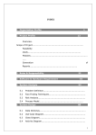
TABLE OF CONTENTS
TITLE PAGE
i
APPROVAL SHEET
ii
ROLES AND RESPONIBILITIES OF GROUP MEMBERS
iii
TABLE OF CONTENTS
iv
LIST OF TABLES
vi
LIST OF FIGURES
vii
ABSTRACT
viii
Chapter 1: DESIGN BACKGROUND AND INTRODUCTION
Customer
Need
Solution
1
1
2
Objectives
Constraints
Impact
Differentiation
3
4
4
5
5
Benefits
Definition of Terms
7
8
Chapter 2: REVIEW RELATED DESIGN LITERATURES AND STUDIES
Accidental Fall Incidents
Fall Detection Approaches and Applications
Accelerometers
Threshold-based tri-axial accelerometer
MEMS accelerometer technology
.NET Framework
ZigBee Technology
Chapter 3: DESIGN PROCEDURES
Hardware Development
9
9
11
14
16
18
20
21
24
24
iv
Software Development
Prototype Development
Monitoring Device Application Software
Chapter 4: TESTING, PRESENTATION, AND INTERPRETATION OF DATA
Treatment of Data
Detection of Fall Testing
33
35
38
41
42
42
Chapter 5: CONCLUSION AND RECOMMENDATION
46
BIBLIOGRAPHY
49
APPENDICES
51
Appendix
Appendix
Appendix
Appendix
Appendix
A – Operation‟s Manual
B – Pictures of Prototype
C – Program Listing
D – Datasheets
E – PCB Design
52
56
58
66
90
v
LIST OF TABLES
Table 1
Roles and Responsibilities
iii
Table 3.1
Bill of Materials
37
Table 4.1.1 Detection of Fall Test for Fall Activities
43
Table 4.1.2 Detection of Fall Test for Non-fall Activities
44
vi
LIST OF FIGURES
Figure 2.1
Human fall detection block diagram
15
Figure 2.2.1 Trunk and thigh resultant signals
16
Figure 2.2.2 Typical fall and normal activity signals
17
Figure 2.3.1 Accelerometer responses to different types of motion
19
Figure 2.3.2 Acceleration change during an accidental fall
20
Figure 3.1
Block diagram of Fall Detection
with Monitoring and Database System
25
Figure 3.2
Detailed Block Diagram
26
Figure 3.3
Collecting signals for the fall detection algorithm
27
Figure 3.4
Fall detection algorithm
28
Figure 3.5
Fall detection with false alarm module
29
Figure 3.6.1 Fall Detection Device Schematic Diagram
31
Figure 3.6.2 Monitoring Device Schematic Diagram
32
Figure 3.7
Windows Application Flowchart
34
Figure 3.8
Monitoring Device Application Main Form
38
Figure 3.9
Fall Incident Notification Form
39
Figure 3.10 Add New Record Form
40
vii
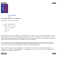
ABSTRACT
The continuous development of fall detection devices serves a great
impact not only to the patients but also to the nursing staffs who observe the
current standing of the patients. Unlike the existing fall detection devices, the
monitoring ratio of the devices one-is-to-one; meaning only one (1) fall sensor
device can send a signal to one (1) monitoring device. In addition, if an incident
happens, no records are kept at all. This paper presents the research and
development of the existing fall detection devices using three-axis accelerometer,
PIC Microcontroller, ZigBee transmitter and receiver, and Arduino Board. The PIC
Microcontroller in the monitoring device was programmed in such a way that
multiple fall sensor devices signals can be interpreted. The Arduino Board serves
as a bridge from the monitoring device to the computer, so that if an incident
happens, the signal from the monitoring device will pass through the Arduino
Board, and the signal will be interpreted by a Monitoring Device Application
Software (MDAS). The MDAS can record the patient‟s name, ID, room number,
time and date of the incident into a database. After the research and
development of the previous systems and the data gathered from the testing, it
is concluded that the device can support two or more sensor devices which may
lessen the cost of a fall detection system. The devices have also provided a
100% of detection for fall incidents. The Monitoring Device Application Software
has provided notification for the monitoring device and the incidents were
recorded into the database of the program.
Keywords: Three-axis accelerometer, Microcontroller, ZigBee, Fall Detection,
Database
viii
Chapter 1
DESIGN BACKGROUND AND INTRODUCTION
This chapter presents a general overview of the design entitled, “Human
Fall Detection with Monitoring and Database System”. It includes a discussion
about the organization which needs a solution to a certain problem, and about
the problem that is aims to be solved. This chapter also provides the solution to
the problem and the objectives proposed to the organization, as well as its
impact and benefits in terms of different factors. The proposed solution is also
distinguished from the existing systems in this chapter.
Customer
The target customer in this design project will provide a solution to the
problem, Lubang District Hospital. It is a small government hospital situated at
Baranggay Tangal, Lubang, Occidental Mindoro. The vicinity can be reached
either by air or sea transportation from Manila or Batangas province, respectively
then a short tricycle ride to Barangay Tangal. It is classified as a Level 1 category
district hospital with a 25-bed capacity. The few patients go in due to active
centers nearby. The severity of the cases that are taken care of the hospital is
low. Cases with higher severity and need immediate attention are taken through
a plane in a small port nearby because the hospital cannot handle such cases
due to lack of modern medical instruments. One nurse, one mid-wife per shift
1
are on job rotation, and the doctor works 24 hours. Most of the patients are
elderly and need attention as well as assistance for their treatment.
Need
Health-related issues are critical for both the patient‟s relatives and health
personnel; one of those issues are human accident falls. Human accident falls
can be characterized into four (4) risk factors. These four (4) risk factors are the
following: (a) Intrinsic – caused by age, low mobility, diseases like Parkinson and
Chronic, low or poor lifestyle, and sight problems like Vertigo, (b) Extrinsic –
caused by drug cocktail, (c) Internal Environment – caused by going up and
down the stairs, slippery floors, and (d) External Environment – caused by
damaged roads, crowded places, poor lighting. These are the factors mostly
cause accidental fall incidents. Those who experience unsupervised fall incident
may suffer psychological effects (fear, anxiety, or depression), physical effects
(injury, fractures, or sometimes even death), and economic effects (fees for
medical examinations, hospital equipments). But the problem with the hospital is
it does not have a low-cost system which can effectively monitor fall incidents.
One reason why people are admitted to hospitals is they want to be
checked-up and/or be cured, which needs to be monitored by the doctors,
nurses, and specialists of their conditions. Monitoring in some public hospitals
like Lubang District Hospital is not at all integrated, unlike in private hospitals
where the monitoring devices are expensive (video and audio monitoring). Also,
2
the number of hospital personnel is very limited to check on over all the patients
at the same time. So, the customer wants to implement a new system wherein
an automatic alarm, specifically for fall incidents can be set and determined
where the patient‟s room is. Further, the customer needs records of fall incidents
so that they can track the patient‟s condition to apply appropriate medical
treatments.
Solution
For a small hospital like this, an inexpensive and reliable fall detection
with monitoring and database system must be implemented. The whole system
is composed of several fall detecting devices which will be worn by the patients
who are experiencing immobility or other factors that can cause a fall accident, a
single monitoring device with database where the fall incidents are recorded, and
an alarm is triggered whenever a patient experiences a fall. The fall detecting
devices use a wireless transmitter to send the signals to the monitoring device,
and an accelerometer to detect the change in orientation of the patient. The
monitoring device with alarm is connected to a computer to sync the data
entering the monitoring device with a program to notify the personnel and to
record the information regarding a certain fall incident. The sensor devices can
simultaneously send signals to the monitoring device where the buzzer alarm will
be triggered, and the computer software will indicate the names and the rooms
of the respective patients which are in need of assistance.
3
Objectives
The objectives of the design project as a solution proposed to the
customer are as follows:
1.
To create a low cost monitoring device that can support two (2) or more
fall detection devices that will use accelerometer and a microcontroller to
sense the orientation of the patient, and ZigBee technology for the
wireless transmission of the signals.
2.
To develop a software that will read the signals from the monitoring
device and display the patient‟s name, room number, and time of event.
3.
To deploy a database system that will store the information from the
Monitoring Device Application Software (MDAS) for further medical use.
Constraints
The distance of the wireless technology used in transmitting the signals
from the sensor device to the monitoring device is limited. Any range farther
than the standard can cause an interruption in the system. The sensor device
must only be worn anywhere along the trunk of the person. It is set to
distinguish a fall from a non-fall based on the center of gravity of the body. But
since some activities have drastic changes in acceleration even if it is a non-fall,
a false alarm button will be set.
The monitoring or receiving device can still generate an alarm even if it is
not connected to the Arduino Board or if the software is not available, but the
4
information regarding the patient who has triggered the alarm will not be
displayed and the incident will not be recorded.
Impact
The health and safety of the patients are very much considered because
having a monitoring device will help in the reduction of psychological and
physical effects concerning the risks of unsupervised fall incidents, as discussed
in the first part of this chapter. The system‟s social impact extends to its
flexibility such that it cannot only be used for hospitals, but it is also essential for
home use. And since the fall detecting device is also flexible to different kinds of
person, there is no need to buy a particular device for a certain type of person. It
can be used by children, elderly, and persons with disability. This relates to
meeting the economic needs of the hospital. Given that the single monitoring
device can accommodate several fall detecting device, the cost of the whole
system will be lessened.
Differentiation
In the past, various solutions have been proposed to detect fall incidents.
One solution is to have the person raise alarm by pushing a button from a
wearable device when they meet an accident. When triggered, it notifies the
hospital through an alarm so that the hospital personnel can provide medical
precautions or actions to the accident. But the problem with this solution is it
depends on the person‟s capability to push the button, and the solution will be
useless if the person become unconscious after the fall since there is a possibility
5
of a head injury. Another solution is the video and audio monitoring wherein
cameras, speakers, and microphones are setup in a room to observe the person,
but these solutions are limited to fixed area and fixed equipments. In addition,
privacy issues are considered which means observers or hospital personnel
cannot monitor the person all day. In recent research, the fall detection is
integrated with a wristwatch wherein it uses accelerometer sensors. The concept
is to calibrate first the accelerometer sensors by slowly rotating the device in
order to project the gravity vector on the three axes in various configurations.
The resulting acceleration signals roughly define the surface of a sphere in a
three dimensional space and having a reference acceleration on the three axes.
Then the device will be worn on the person‟s wrist for observations. When worn,
if a fall happens, there is a sudden change in acceleration on the three axes
giving a signal, which transmits through wireless network via Bluetooth, to a
guardian or hospital personnel that a fall happened.
In some cases (fall from a chair), a fall may occur without moving the
arms drastically, causing change in acceleration. Given these situations, the
setback of the recent device, since it is placed on the wrist, is it will only be
effective for detecting falls from a much higher space (i.e. 3-4 feet higher),
because the whole body must experience the fall for the accelerometer to detect
sudden change in acceleration. Also, the arms are very prone to unnecessary
movement, such as swaying which may also cause sudden change in
acceleration even if the body is not experiencing a fall.
6
Most rooms for patients in hospitals and clinics are installed with phones
direct to the nurse station or wards so that when the patients need assistance or
for emergencies reasons, they can immediately call the attention of the nurses or
hospital personnel. The problem with this kind of system is when a fall incident
happens there is a possibility that the patient can be injured or fractured; or be
unconscious, which means they are not capable to call for assistance. Also, with
all of these existing solutions for fall detection and monitoring, the ratio of the
sensor device to the monitoring device is one-is-to-one. This means that for
every patient, different set of systems will be needed. This will not be practical
for the hospital since the budget is considered.
Benefits
The system is beneficial to the hospital because it costs cheaper due to
the many-to-one ratio of the fall detecting device to the monitoring device. And
since a database is provided, the monitoring device can easily determine who
among the persons wearing the fall detecting device has experienced a fall. The
device can help guardians and/or hospital personnel on how they will be
informed about the situation of the patient to immediately attend to any fall
incidents and lessen the damages caused by accident. It may also help the
casualty to prevent/remove after-effects physically (such as injury, fractures,
etc.), psychologically (such as fear, anxiety or depression), and economically
(unwanted and high cost medical fees).
7
Definition of Terms
1.
Accelerometer.
An
electromechanical
device
that
will
measure
acceleration forces. These forces may be static, like the constant force of
gravity pulling at your feet, or they could be dynamic - caused by moving
or vibrating the accelerometer. (Dimension Engineering, 2012)
2.
Microcontroller. A single chip that contains the processor (the CPU),
non-volatile memory for the program (ROM or flash), volatile memory for
input and output (RAM), a clock and an I/O control unit. (PC Magazine,
2012)
3.
Database.
A
data
structure
that
stores
organized
information.
(TechTerms Inc., 2012)
4.
ZigBee. A wireless technology developed as an open global standard to
address the unique needs of low-cost, low-power wireless M2M networks.
(Digi International Inc., 2012)
5.
Arduino. An open-source electronics prototyping platform based on
flexible, easy-to-use hardware and software.
8
Chapter 2
REVIEW OF RELATED DESIGN LITERATURES AND STUDIES
This chapter provides a short overview about a fall detecting device and
its application as a health care system. The researchers have gathered the
following previous studies, articles, and journals which are related to the design
project entitled, "Human Fall Detection With Monitoring And Database System."
The collection of citations will be used as a reference in developing the proposed
system.
Accidental Fall Incidents
A fall can be defined as unintentionally coming to the ground or some
lower level and other than as a consequence of sustaining a violent blow, loss of
consciousness, sudden onset of paralysis as in stroke or an epileptic seizure
(Gibson et al., 1987). For those who live at home, almost half of the falls take
place near or inside the house (Campbell et al., 1990; Lipsitz et al., 1991).
According to Hammadi Nait-Charif and Stephen McKenna in their study “Activity
Summarisation and Fall Detection in a Supportive Home Environment” (2004),
home environments are able to monitor automatically the activities of their
occupants can help extend independent, quality living, and reduce healthcare
costs. Majority of people who experience accidental falls are children, the elderly,
and persons with disability due to the reduction in their mobility.
9
Ge Wu and Shuwan Xue wrote the article “Portable Preimpact Fall
Detector With Inertial Sensors” (2008) mentioned that hip fractures are the most
common fall-related problem. Wu et al. (2008) cited that falls may occur in many
ways such as backward falls, forward falls, sideway falls, and straight-down falls
(Smeesters et al., 2001). The author of the publication “Reduce Accidental Falls
in Your Home”, Claudia C. Collins, stated that between 30-60% of adults over
age 65 fall each year. And, of the more than 200,000 elders who experience hip
fractures each year, nearly one third result in death, less than a half return to full
function, and 30% of survivors require long-term care (Collins). Moreover, in a
study entitled “A Study on Detection of Risk Factors of a Toddler‟s Fall Injuries
Using Visual Dynamic Motion Cues” (2009), the author Hana Na avowed that
young children are not able to assess risks for themselves. They also have poor
coordination and balance and need to touch and explore to learn about the world
around them. These factors all mean that children are particularly vulnerable to
accidents (Na, 2009). Although the other consequences of accidental falls may
be minimal such as scratches and bruises, it is still a high risk for people who
stay in a room alone or those who has mobility incapability.
In a survey conducted by Abbate, Avvenuti, Corsini, Vecchio, and Light,
entitled “Monitoring of human movements for fall detection and activities
recognition in elderly care using wireless sensor network”,stated that accidental
falls among elderly people are the main cause of admission and extended period
of stay in a hospital. Statistics revealed that it is the sixth cause of death for
10
people age 65, the second for people between 65 and 75, and the first for
people over 75 (Bradley et al., 2009). The survey also showed that among the
people affected by Alzheimer‟s disease, the possibility of a fall is increased by a
factor of three.
Na stated in her study that on the average, over two million children per
year in the United Kingdom are taken to the hospital after having an accident,
and approximately two hundred children per day are hospitalized and one child
dies as a result of unintentional injuries in Australia. Most of the fall incidents
take place at home where children below five years old are the most vulnerable
to injuries because this is where they spend most of their time. Falls account for
over 40 per cent of all home accidental injuries on children (Na, 2009).
Fall Detection Approaches and Applications
There are different approaches to monitor a certain patient with regard to
fall incident. Push buttons can be used as a trigger to alarm the guardian; the
implementation of audio and visual monitoring; and embedding motion sensors
like accelerometers on a wristwatch and detecting a certain fall incident. But
these approaches have unique disadvantages: (1) when an incident happens, if
the patient becomes unconscious, he/she is not capable to trigger an alarm using
a push button; (2) privacy issues and high-cost implementation for the audiovisual monitoring; and (3) using wristwatch is prone to a drastic change in
acceleration, like swaying of arms, that can lead to a false alarm.
11
Because of these incidents and the threat for people‟s safety, certain
techniques and technologies have been developed to improve the monitoring of
the patients‟ activities. Tong Zhang, Jue Wang, Liang Xu, and Ping Liu mentioned
in their study entitled “Fall Detection by Wearable Sensors and One-Class SVM
Algorithm” (2006), said that the early detection of a fall is very important to
rescue the subjects and avoid the badly prognosis. This makes the development
of this type of technology to be important to assist and to protect people
experiencing difficulty in balance.
In the study conducted by Abbate et al., cited related surveys of research
on patient monitoring technologies. In their citation, Noury et al. (2007)
described a system, algorithm, and sensors used for fall detection of elderly
people. They discovered the lack of common framework and proposed some
performance evaluation parameters in order to compare different systems
(Abbate et al.). Another was Yu (2008), who focused on a classification of the
approaches and principles of existing fall detection methods. He provided a
classification of falls and a general framework of fall detection, alert device, and
system scheme.
In the research work “Fall Detection and Activity Recognition with Machine
Learning” written by Lustrek et al. (2009), he enumerated four types of
approaches to fall detection – (a) the first approach is by the use of
accelerometers, typically three-axis accelerometers, which is a device for
detecting magnitude and direction of acceleration caused by the pull of gravity
12
along a single axis; (b) the second approach uses gyroscopes, where the object
is equipped with gyroscopes along with three axes and detects the object‟s
orientation and change in orientation, from which the angular velocity is
computed;
(c)
the
third
is
denoted
visual
detection
without
posture
reconstruction which is based on extracting input data from still images or video;
and (d) the last is visual detection with posture reconstruction which is based on
3D locations of markers placed on an object or the human body.
Latest technologies today include handheld devices or wearable devices
which send signals into a certain system or station to indicate that an accidental
fall has occurred. Zhang et al. (2006) described these wearable sensors as a
means of embedding micro sensors into clothes, girdle, etc., to monitor the
movement parameters of human body in real-time, and determine whether there
is a fall that occurred based on the analysis about the parameters. But the
authors said that there exist many problems about this kind of algorithms;
include lacking of adaptability, deficiently in classification precision, etc.
As mentioned in one of the approaches, the study will focus on the use of
three-axis accelerometers to detect fall detection and the device will be
embedded with a ZigBee wireless transmitter to forward data to a remote system
which will manage the monitoring of the patient. Since the different kinds of fall,
as mentioned earlier in this chapter, have their own distinct characteristics, the
flexibility of the detecting device must be considered in order to develop a fully
efficient and effective system. To solve the dilemma of adaptability, the
13
researchers proposed a clipped-style sensor to be placed near the belly of the
user. According to the study carried out by Wu et al. (2008), they have stated it
was hypothesized that a single sensor with the appropriate kinematics
measurements and detection algorithms, located near the body‟s center of
gravity, would be able to distinguish an in-progress and unrecoverable fall from
non-falling activities. Thus, the effectiveness of the signals which will be sent to
the remote system would be most likely higher, compared to the detection of a
device which is worn on the wrist or used a device used as a pendant. These
positions of the devices are inclined to the detection of sudden change in
acceleration due to involuntary or spontaneous movements such as swaying or
other movements which require the use of the arm; and may trigger the sending
of data into the remote system even if it is not an actual fall which requires
attention.
Accelerometers
Dimension Engineering, a manufacturer of electronic and electromechanical parts, has published “A beginner‟s guide to accelerometers” where
they described an accelerometer as a device which measures acceleration forces.
They said that by measuring the amount of static acceleration due to gravity, the
angle at which the device is titled with respect to the earth may be computed.
From a product description of Modern Device, they stated that by sensing the
amount of dynamic acceleration, the accelerometer can measure how fast and in
14
what direction the device is moving. By these two properties of an
accelerometer, it may be used together with other algorithms to detect human
fall instances.
Another guide published by Parallax Inc. (2005), it was mentioned that
the use of an accelerometer can be very useful for various applications such as
self-balancing robots, tilt-mode game controllers, car alarm systems, crash
detection, leveling tool, human monitoring, etc.
2005
Figure 2.1 Human fall detection block diagram, Source: Reyna et al.,
Freescale Semiconductor Inc. has issued a reference manual entitled
“Human Fall Detection Using Three-Axis Accelerometer” in 2005, developed by
Rogelio Reyna, Edgard Palomera, Rogelio Gonzalez, Sergio Garcia de Alba, and
Michelle Clifford. The document contains information about the application of the
three-axis low g accelerometers (MMA7260Q), 2.4 GHz RF transceiver data
15
modem for 802.15.4 applications (MC13192), and the Digital Signal Controllers
from Freescale (MC56F8013). As illustrated in Figure 2.1 is the block diagram of
the hardware module. This can be used as a reference for the implementation of
the device proposed in this thesis.
Threshold-based tri-axial accelerometer
The study by Bourke, O‟Brien, and Lyons (2006) entitled “Evaluation of a
threshold-based tri-axial accelerometer fall detection algorithm” described the
development and testing of a threshold-based algorithm which can determine an
actual fall event from a usual daily activity, using tri-axial accelerometers. The
accelerometers which they will place on the trunk and thigh will have peak
values during a fall, which will be distinct from the signals produced during the
performance of a normal activity (Bourke et al., 2006).
2006
Figure 2.2.1 Trunk and thigh resultant signals, Source: Bourke et al.,
16
2006
Figure 2.2.2 Typical fall and normal activity signals, Source: Bourke et al.,
According to the study, the resultant signal from both the tri-axial
accelerometer sensors at the trunk and the thigh were derived by taking the
root-sum-of-squares of the three signals from each tri-axial accelerometer
recording. They had defined four threshold values: upper and lower fall
thresholds for both the trunk, and the thigh. As an algorithm example, they have
used artificial sample signals in Figure 2.2.1: trunk and thigh resultant vector
signals; and in Figure 2.2.2: a typical fall (K), a fall that produced the smallest
upper peak value (L), a fall the produced the smallest power peak value (M), a
typical sitting on an armchair activity (N), getting in and out of a car seat activity
(O), and walking (P).
17
The authors also stated that the type of sensor used in their study could
be woven into a tightly fitting garment and the tri-axial accelerometer could be
mounted onto a flexible PCB with a wireless connection to monitoring electronics.
As their suggestions for further developments, the device could be incorporated
into a portable unit, capable of both fall detection as well as mobility monitoring
upon detection of a fall, an emergency message could be sent through GSM
model in form of SMS. In the researches‟ study, the device for the detection of a
fall will be incorporated into a portable unit, but is restricted to SMS alert.
Instead, the researchers have proposed a wireless transmission into a remote
system or unit to alert or to notify that a fall occurrence.
MEMS accelerometer technology
A field applications engineer of Analog Devices Inc., Ning Jia wrote the
article “Human Fall Detection Using New MEMS Accelerometer Technology”
(2009),
where
he
discussed
the
technological
advances
in
micro-
electromechanical system (MEMS) acceleration sensors have made it possible to
design fall detectors based on a three-axis integrated MEMS accelerometer. In
his study, the fall detector is mounted to a belt on the individual‟s body while
performing different types of activities. The changes in acceleration while (a)
walking downstairs, (b) walking upstairs, (c) sitting down, and (d) standing up
from a chair are illustrated in Figure 2.3.1.
18
He said that since the movement of elderly people is slow, the
acceleration change will not be drastic during walking motions. But the
accelerations during a fall change notably. In Figure 2.3.2, the acceleration
change during an accidental fall is shown. The four critical differences
characteristics of a falling event can be used as criteria for fall detection (Jia,
2009).
Figure 2.3.1 Accelerometer responses to different types of motion, Source:
Jia, 2009
19
Figure 2.3.2 Acceleration change during an accidental fall, Source: Jia, 2009
.NET Framework
The .Net framework is a windows component that allows users to build,
execute and deploy .net applications and XML services. The .Net Framework is
designed to provide consistency in programming whether it is stored or executed
locally or internet-distributed or externally executed or remotely. It also provides
code-execution environment to avoid software deployment and version conflicts,
promotes safe execution of code either by external or third party codes, and
eliminates performance problems of scripted environments. Furthermore, the
.Net Framework makes the developer experience consistency among diverse
types of application such as window based or web based applications. It also
ensures that the code based on .net framework will be able to be integrated with
any other code.
20
The .NET Framework has two main components: the common language
runtime and the .NET Framework class library. The common language runtime is
the foundation of the .NET Framework. The runtime acts as an agent that
manages code at execution time, providing core services such as memory
management, thread management, and remoting, while also enforcing strict type
safety and other forms of code accuracy that promote security and robustness,
the concept of code management is a fundamental principle of the runtime.
Managed code is a type of code that targets the runtime or the codes in runtime,
while the unmanaged code does not. In .Net Framework Technology, there is a
so-called “class library” which contains an object-oriented collection of reusable
type that can be used to develop applications from CLI or Command-Line
Interface, GUI or Graphical User Interface to the latest innovations provided by
the framework such as web forms and XML services.
ZigBee Technology
ZigBee is the set of specifications built around the IEEE 802.15.4 wireless
protocol. The IEEE is the Institute of Electrical and Electronics Engineers, a nonprofit organization dedicated to burden technology involving electronics and
electronic devices. The 802 group is the section of the IEEE involved in network
operations and technologies, including mid-sized networks and local networks.
Group 15 deals specifically with wireless networking technologies, and includes
the now ubiquitous 802.15.1 working group, which is also known as Bluetooth®.
21
The standard itself is regulated by a group known as the ZigBee Alliance, with
over 150 members worldwide. ZigBee devices are actively limited to a throughrate of 250 Kbps, compared to Bluetooth's much larger pipeline of 1Mbps,
operating on the 2.4 GHz ISM band, which is available throughout most of the
world. (Brendan McGuigan, 2012)
According to Gary Legg, technologists have never had trouble coming up
with potential applications for wireless sensors. This is due to Wireless sensors
are easier to install than wired sensors. Even for large industry environments,
large amount of cost is spent for hard wired sensors. Then there comes the
wireless sensors, where wiring is not practical or applicable. The problem now is
that the wireless sensors uses too much power, therefore their power supplies
must be large enough but not the batteries to be replaced often. Moreover, some
doubt the reliability of the sensor data that is sent across the air.
Most of the time, a ZigBee node is at sleep-mode for saving power, if
necessary, it triggers to active-mode then sends the data and then goes back to
sleep-mode again. And, because ZigBee can transition from sleep mode to active
mode in 15 msec or less, even a sleeping node can achieve suitably low latency.
Someone flipping a ZigBee-enabled wireless light switch, for example, will not be
aware of a wake-up delay before the light turns on.
Another factor for conservation of power comes from the radio technology
of 802.15.4. It uses Direct-Sequence Spread Spectrum technology (DSSS) which
22
accounts for direct transfer of data unlike in FHSS or frequency-hopping spread
spectrum that needs more power in keeping its frequency hops synchronized.
To save as much power as possible, ZigBee employs a talk-when-ready
communication strategy, simply sending data when it has data ready to send and
then waiting for an automatic acknowledgement. According to Bob Heile, who is
chairman of both the ZigBee Alliance and IEEE 802.15, talk-when-ready is an "inyour-face" scheme, but one that is very power efficient. "We did an extensive
analysis that led to the best power-saving strategy on various kinds of
environments from quiet to noisy," Heile says. "We discovered that, hands down,
we were better off just sending the packet and acknowledging it. If you don't get
an ack, it just means you got clobbered, so send it again. You wind up having
much better power management than if you listen and determine if it's quiet
before you talk." (Gary Legg, 2004)
23
Chapter 3
DESIGN PROCEDURES
This chapter gives the discussion about the procedures and methods used
in designing and developing the proposed system of the design project entitled,
“Human Fall Detection with Monitoring and Database System.” The procedures
concerning the hardware, software, and prototype development of the system
are specifically described in this chapter. The hardware development discusses
the system in terms of block and schematic diagrams, as well as the functions of
each part. The software development is explained through program flowcharts,
and the prototype development gives the details about the materials and
components used in assembling the prototype.
Hardware Development
The researchers have gathered information about the assembly of the
previous systems, such as circuit designs and the components used. These were
used as basis in designing the hardware part of the system. The components
used in the proposed system were thoroughly researched to come up with a cost
effective and more convenient fall detection and monitoring device. After
collecting the information, the components were chosen and the working circuits
were designed. These were simulated through certain software and the
prototype was constructed.
24
Multiple
Sensors
Application
Software
Monitoring
Device
Arduino
Board
Database
Computer
Figure 3.1 Block diagram of Fall Detection with Monitoring and Database
System
Figure 3.1 illustrates the block diagram of the system. The first approach
in developing the system proposed in this study is to incorporate the sensor
device into a portable clipped-device. The sensor that will be used is a three-axis
accelerometer. Then an algorithm will be developed to detect an actual fall from
a normal day activity using a PIC Microcontroller, and may also receive an
interruption whether the sent information is a false alarm. Then the sensing
device will send data into a remote monitoring device to alert that there is an
occurrence of a fall. The remote monitoring device is programmed in such a way
that it can detect multiple sensing devices. After receiving the information from
the remote monitoring device, it forwards the information to a Monitoring Device
Application Software via Arduino Board to record data using database system.
Figure 3.2 shows a detailed block diagram of the fall detection and monitoring
with database system.
25
Three-axis
Accelerometer
PIC
Microcontroller
Interrupt 1
ZigBee
Transmitter
Zigbee
Receiver
Three-axis
Accelerometer
PIC
Microcontroller
Interrupt 2
PIC
Microcontroller
ATmega328
Microcontroller
Arduino Board
Alarm system
ZigBee
Transmitter
Database (SQL)
Computer
Three-axis
Accelerometer
PIC
Microcontroller
Monitoring
Device
Application
Software
(MDAS)
Interrupt
Nth
ZigBee
Transmitter
Figure 3.2 Detailed Block Diagram
26
The process begins with designing a convenient clip-on casing where the
three-axis accelerometer module will be incorporated. The portability of the
design will allow the patient to simply clip-on the device in their trunk. The threeaxis accelerometer will be used to measure the change in acceleration for each
normal activity of the user.
Then the device will be tested and calibrated first to gather signals needed
for the design of the algorithm for fall detection. The process is exemplified in
Figure 3.3. The data collected will be stored into the microcontroller and a
corresponding algorithm will be applied to determine a normal day activity from
an incidental fall. These data include the change in acceleration while the person
is doing normal day activities such as walking, sitting on a chair, getting up from
bed, etc.
Normal Day
Activities Signal
Three-Axis
Accelerometer
PIC
Microcontroller
Figure 3.3 Collecting signals for the fall detection algorithm
After the gathering the accelerometer readings for typical daily activities
and storing it into the microcontroller, the algorithm for fall detection will be
developed as shown in Figure 3.4. The process is continuous to make it a realtime system that can detect a fall incident at any given time.
27
Start
Detect signals from
accelerometer
Drastic
change in
acceleration?
No
Yes
Compare with normal
day activity signals
Unusual
signals?
No
Yes
Generate alert
End
Figure 3.4 Fall detection algorithm
The signals from the three-axis accelerometer will be sent into the
microcontroller. If a drastic change in acceleration is observed, the signals will be
processed and will be compared with the usual daily activity signals.
The
28
microcontroller will indicate a fall incident if the input signals show very distinct
characteristics from the normal activity signals. In the event of a fall, the device
will emit a sound alarm to notify the patient wearing the device that the incident
has already been reported to the remote monitoring device and a record will be
added into the database. The transmission will be discussed in the later part of
this chapter.
To ensure the consistency of the device, a „false alarm‟ module will be
added to it. There may be instances where the person had almost fell but was
able to instantly recover from the fall, thus a button will be triggered in case the
incident does not need immediate attention or it is a false fall. The integration of
this module with the system is described in Figure 3.5.
Start
Detect for a fall
incident
Is there a fall
incident?
Generate alarm
No
No
False alarm
triggered?
Yes
Generate false alarm
End
Figure 3.5 Fall detection with false alarm module
29
If a fall has been detected by the device, the system will generate an
alarm. The patient can also send an interrupt signal indicating that it is a false
fall or if he/she doesn‟t need any immediate assistance.
The last part in the development of the system is the wireless
transmission of the fall alarm and interrupts using ZigBee technology. It is
embedded together with the three-axis accelerometer module, and a remote
receiving system will be used for monitoring the patient‟s activities. ZigBee is
used in this paper because it is designed for wireless controls and sensors. It
allows wireless one-way communication and travels across greater distances and
handles many sensors that can be linked to perform different tasks. ZigBee is a
wireless protocol that allows users to build medium to large networks of sensors
and controllers. It transmits packets from the accelerometer and microcontroller
to the receiver via wireless connection. The receivers are characterized by high
stability and reliability of performance, and are generally adapted for remote
control and monitoring. It will be used to accept signals or packets from the
accelerometer and microcontroller through the ZigBee transmitter and then
translate signals into a usable form for the destination.
The generated signals from the microcontroller will be passed to the
ZigBee transmitter and the data will be sent to the receiver via wireless
connection. The remote monitoring device consists of the receiver and alarm
mechanism, and connected to a personal computer with a Monitoring Device
Application Software via Arduino Board. Upon receiving the data from the
30
transmitter, the receiver translates the signal and the system will indicate that
there is an occurrence of a fall through LCD display and buzzer. In addition, the
received signal from the microcontroller will be recorded in a database via
Arduino Board. The database will record the Patients‟ Number, Name, Room
Number, Fall or False Fall, as well as what kind of assistance or medical
procedures will be given. It may also be possible that an interruption signal will
be received from the device if the false fall alarm is triggered. Thus, two alarm
signals will be the output of the remote monitoring device.
Figure 3.6.1 Fall Detection Device Schematic Diagram
31
Figure 3.6.2 Monitoring Device Schematic Diagram
Figures No. 3.6.1 and 3.6.2 show the interconnection of the components
for the sensor and monitoring devices, respectively. PIC18F1220 with 18 pins
was used for both the circuits to process the information. The accelerometer was
used to detect the change in orientation of the patient, and the signals were
processed by the microcontroller. If an alarm is triggered, a signal is transmitted
via ZigBee transmitter. It is then received by the monitoring device using a
ZigBee receiver and the microcontroller initializes the alarm with a buzzer and
the LCD display.
32
Software Development
The application used in developing the software part of the system is
Microsoft .NET Framework. The windows application is built using Visual C#
which supports access to a serial port. The programmer used SQL Server to
access the database. The database is created using the .NET Framework Data
Provider for SQL Server.
The signals from the receiver were accessed using the I/O pins of the
Arduino Board. This board‟s microcontroller was programmed using the Arduino
programming language, which was similar to C or C++ language. The board is
connected to the computer using a USB port and the C# application processes
the signals sent by the Arduino Board.
The researchers‟ first step in developing the software is to develop the
flowchart of the system to visualize the flow of information. The whole system is
considered including the signals from the receiver and the database. Figure 3.7
illustrates the flowchart.
33
Start
Input admin
password
Initialize program
Receiver
sends
signal?
No
Yes
Get patient number
Search database
Output patient name,
room number, date
and time
Store
information
to database
End
Figure 3.7 Windows Application Flowchart
34
The system has only one administrator account to manage the software.
Only the password can be modified but the user name is set constant. The
administrator can manage the record of patients included in the system. A
primary key is used which is the patient number to identify which device is worn
by the patient. The patient number is the same with the device number. So
whenever a patient will be released from the hospital, the administrator can
delete the information such as the name and room number that is assigned to a
patient number, and then add a new one if it will be used.
Upon running the program, the user is asked to enter the administrator
password to access the program. Then the monitoring device waits for any alarm
trigger that signals a fall incident. The sensor device sends a signal to the
receiver and the Arduino board will distinguish the patient number based on the
activated port. The program then processes the information and searches the
database. It then displays the patient‟s name, room number, the time, and date
of the incident. These are also recorded in another database for further use.
Prototype Development
After designing the block diagram of the system and selecting the
components to be used, the researchers have developed the prototype by
following these certain procedures:
1.
Identify all the components that will be used for the assembly of the
device. Provide a complete list of the materials.
35
2.
Design the circuit diagram. Show all the interconnections of the
components listed for the sensor device and the monitoring device.
Multisim was used to design the circuit.
3.
Construct the layout of the circuit in PCB Wizard. Place all the components
and the connections of the circuits. Print the layouts in a transparent film
for photo etching.
4.
Etch the printed circuit board based on the printed layout. Test the board
for continuity to avoid any malfunctions in the circuit. Drill the board
properly where the components will be mounted. Solder all of the
components based on their connections.
5.
Program both of the PIC18F1220 microcontrollers based on the fall
detection algorithm and the receiving of data in the monitoring unit.
Proton IDE was used to program the microcontrollers.
6.
After debugging the program, it is then compiled and a hex file is
generated. This is the format that is read by the microcontroller.
7.
Burn the hex file to the microcontroller using PIC Kit 2. Test the devices if
the expected outputs are met.
8.
Connect the output port of the monitoring device to the Arduino board.
The board used is Arduino Deumilanove with ATmega328.
36
Table 3.1 shows the components used in building the prototype and the
bill of materials.
QTY:
ITEM NAME:
Description
COST
1 PC.
Three Axis Accelerometer
SCA3000
650.00
3 PC.
XBee
2,775.00
1 PC.
Zigbee
2Transmitter/1Reciever
Microcontroller
PIC18F1220
205.00
1 PC.
IC Socket
18-Pin
30.00
5 Pcs.
Capacitor
1k µF
5.00
2 Pcs.
Crystal Sine Generator
4MHz
2.50
2 Pcs.
Switching Diode
1N4148
2.00
3 Pcs.
Push Button
-
15.00
1 Pc.
Buzzer
-
30.00
1 PC.
LED
-
3.00
2 Pcs.
Voltage Regulator
RT9163
50.00
5 Pcs.
Resistor
22K Ω
5.50
3 Pcs.
Casing
-
60.00
1 Pc.
LCD Display
2x16
450.00
2 Pcs.
Battery
9V
120.00
1 Ps.
Slide Switch
-
6.00
1 Pc.
Board w/ Microcontroller
Arduino Duemilanove with
875.00
ATmega328
1 Pc.
Connector M/F
2-Pin
10.00
1 Pc.
Connector M/F
4-Pin
15.00
1 Pc.
Connector M/F
8-Pin
25.00
LE50
10.00
2 Pcs.
TOTAL: Php 5344.00
Table 3.1 Bill of Materials
37
Monitoring Device Application Software
The monitoring software where the details regarding the patients are
displayed is built with a Graphical User Interface. Visual Studio C# was used to
develop the GUI-based windows application. The main form of the program is
shown in Figure 3.8.
Figure 3.8 Monitoring Device Application Main Form
38
Figure 3.8 shows the main form of the program. There is a list where the
patient‟s ID, name, and room of all the patients wearing the sensor devices are
displayed. Another list is created for the list of the incidents. The time and date
of the incident are recorded in the database. The user can refresh the list if ever
another incident has occurred. The list can also be cleared from the form and
from the database, and a warning window is added to verify if the clearing will
be performed.
Figure 3.9 Fall Incident Notification Form
The administrator is notified when a fall has occurred and details
regarding the patient is shown in a form in Figure 3.9. The form will only be
closed if the administrator has already responded to the incident. The incident
will be recorded to the database.
39
Figure 3.10 Add New Record Form
If the administrator wishes to add another record, the form in Figure 3.10
is used. The patient‟s ID is predefined based on the available device for use.
40
Chapter 4
TESTING, PRESENTATION, AND INTERPRETATION OF DATA
This chapter discusses the testing procedures made for the system to
assess if the stated objectives in the first chapter are met. Different testing types
and procedures were implemented to the prototype after the assembly.
The researchers provided three testing procedures to test the efficiency of
the device. The first test is to identify a certain activity if it is a fall or a non-fall;
second test is for the response time of the system or how fast the device will
send an alarm to the remote monitoring device with respect to the type of fall;
and the third test is for the response time of the system depending on the
distance of the device from the remote monitoring device.
The fall detection device must be placed or clipped on the trunk of the
user before turning it on to calibrate the three-axis accelerometer. Then after
turning on the remote monitoring device, the user can perform his/her usual
activities. For the purpose of testing, the user will imitate an occurrence of a fall
and the remote monitoring device will be observed if it will indicate an alarm or
not.
The alarm consists of an LCD display and a buzzer. If the system notifies
an occurrence of a fall, then the person monitoring the user can press a button
on the remote monitoring device to stop the sound of the alarm if he/she has
already been notified.
41
Treatment of Data
The researchers used the following formula to calculate the percentage of
detecting an actual occurrence of a fall based from the data gathered. With
these data, the researchers can determine the percentage of detection of the
device for a particular activity. The percentage of detection can be calculated
using the following formula:
Also, the average response time of the monitoring device to generate an
alarm will also be computed to establish if the use of Zigbee technology will be
more effective, with respect to the type of fall and the distance of the transmitter
from the receiver. The following formula will be used:
where
and
is the response time with respect to the type of fall,
is the response time with respect to distance.
Detection of Fall Testing
For the first test procedure, the researchers will distribute the thirty
samples by age and by capability. Ten, fifteen, and five samples will come from
children (1 – 9 years old), adolescent-and-above (10 years old and above), and
42
persons with disability, respectively. Each sample will follow the type of activity
provided by the researcher. The device will detect for that particular activity if it
is a fall or not. Table 4.1.1 and Table 4.1.2 are used to record the data.
Table 4.1.1 Detection of Fall Test for Fall Activities
Trial
1
2
3
4
5
6
7
8
9
10
11
12
13
14
15
16
17
18
19
20
21
22
23
24
25
26
27
28
Type of
Person
Children
(1-9 yrs old)
Adolescent
(10 and
above)
Persons
with
Disability
Fall While
Walking
Fall
Fall
Fall
Fall
Fall
Fall
Fall
Fall
Fall
Fall
Fall
Fall
Fall
Fall
Fall
Fall
Fall
Fall
Fall
Fall
Fall
Fall
Fall
Fall
Fall
Fall
Fall
Fall
Detection
(Fall/Non-fall)
Fall
Fall From
While
Bed
Standing
Fall
Fall
Fall
Fall
Fall
Fall
Fall
Fall
Fall
Fall
Fall
Fall
Fall
Fall
Fall
Fall
Fall
Fall
Fall
Fall
Fall
Fall
Fall
Fall
Fall
Fall
Fall
Fall
Fall
Fall
Fall
Fall
Fall
Fall
Fall
Fall
Fall
Fall
Fall
Fall
Fall
Fall
Fall
Fall
Fall
Fall
Fall
Fall
Fall
Fall
Fall
Fall
Fall
Fall
Fall
Fall
Fall From
Chair
Fall
Fall
Fall
Fall
Fall
Fall
Fall
Fall
Fall
Fall
Fall
Fall
Fall
Fall
Fall
Fall
Fall
Fall
Fall
Fall
Fall
Fall
Fall
Fall
Fall
Fall
Fall
Fall
43
29
30
Fall
Fall
Fall
Fall
Fall
Fall
Fall
Fall
Table 4.1.1 (Detection of Fall Test for Fall Activities) shows the response
of the devices to a particular activity if a fall happens. These activities are fall
incidents while walking, standing, from stairs, and from chair. Based on the
results, the formula for percentage of detection will then be applied for the fall
and non-fall activities. It can be clearly seen that the device has successfully
detected all kinds of fall that were set by the researchers, but some non-fall
activities were detected as fall occurrence. The result is that the device can
detect a fall from all the activities provided giving the researcher a 100%
detection.
Table 4.1.2 Detection of Fall Test for Non-fall Activities
`Trial
1
2
3
4
5
6
7
8
9
10
11
12
13
14
Type of
Person
Children
(1-9 yrs old)
Adolescent
(10 and
above)
Walking
Non-fall
Non-fall
Non-fall
Non-fall
Non-fall
Non-fall
Non-fall
Non-fall
Non-fall
Fall
Non-fall
Non-fall
Non-fall
Non-fall
Detection
(Fall/Non-fall)
Sitting
Walking
Upstairs
Non-fall
Non-fall
Fall
Non-fall
Non-fall
Non-fall
Non-fall
Non-fall
Non-fall
Non-fall
Non-fall
Non-fall
Fall
Non-fall
Non-fall
Non-fall
Fall
Non-fall
Fall
Fall
Non-fall
Non-fall
Non-fall
Non-fall
Non-fall
Fall
Non-fall
Non-fall
Walking
Downstairs
Fall
Fall
Non-fall
Non-fall
Non-fall
Non-fall
Fall
Fall
Fall
Fall
Fall
Non-fall
Fall
Fall
44
15
16
17
18
19
20
21
22
23
24
25
26
27
28
29
30
Persons
with
Disability
Fall
Non-fall
Non-fall
Non-fall
Non-fall
Non-fall
Non-fall
Non-fall
Non-fall
Non-fall
Non-fall
Non-fall
Non-fall
Non-fall
Non-fall
Non-fall
Non-fall
Non-fall
Non-fall
Non-fall
Non-fall
Non-fall
Fall
Non-fall
Non-fall
Non-fall
Fall
Non-fall
Non-fall
Non-fall
Non-fall
Non-fall
Fall
Non-fall
Non-fall
Non-fall
Non-fall
Non-fall
Fall
Fall
Non-fall
Non-fall
Non-fall
Fall
Non-fall
Non-fall
Fall
Non-fall
Fall
Non-fall
Non-fall
Non-fall
Non-fall
Non-fall
Fall
Non-fall
Fall
Fall
Fall
Fall
Fall
Non-fall
Non-fall
Non-fall
Table 4.1.2 (Detection of Fall Test for Non-Fall Activities) shows if the
device will detect a fall or alarms even though the particular activity is a non-fall.
These activities are walking, sitting, walking upstairs and downstairs. For walking
– 93.33%; sitting – 80.00%; walking upstairs – 76.67%; and walking downstairs
– 46.67%. The average percentage of detection is 74.17%. Of all the activities
that were tested, walking downstairs would not reach the acceptance to meet
the objective. So as a solution, a false fall alarm was added to the system. The
participants can give information to the remote monitoring user that a false fall
happened. One good reason for a false detection of the device is the sensitivity
of it. The researchers set the degree of detection to 80° to 90°, which is too
high. So, the researchers can lower the degree of detection to change the
percentage of the outcomes.
45
Chapter 5
CONCLUSION AND RECOMMENDATION
This chapter presents the conclusion of the study and implementation of
the design project entitled, “Human Fall Detection with Monitoring and Database
System”, and the recommendations from the researchers to further improve the
system.
Conclusion
The objectives of this study are to create a low cost monitoring device
that can support two (2) or more fall detection devices using an accelerometer
and a microcontroller to sense the orientation of the patient, and ZigBee
technology for the wireless transmission of the signals; to develop a software
that will read the signals from the monitoring device and display the patient‟s
name, room number, time of event, and to deploy a database system that will
store the information from the Monitoring Device Application Software (MDAS)
for further medical use.
After researching and developing the existing fall detection system, based
from the results of each test, the researchers found out that the device can
support two or more sensor devices, which means the implementation of the
system may be considered low-cost since users or implementers need only one
46
monitoring device. In addition, the devices have provided a 100% detection of
fall giving the researchers as well as the users a high acceptance for the device.
The positioning of the device in the user‟s body is also significant to
distinguish a fall from a non-fall. Since it is clipped on the trunk on the user
which is the center of gravity of the body, it is also more convenient to be worn
on a daily basis because it cannot cause distraction to our daily activities, unlike
the previous devices were embedded into belt-types, pendant-types, or even
worn at the wrist.
The researchers also considered the notifications from the Monitoring
Device Application Software wherein two (2) or more sensor devices will send an
alarm signal at the same time. After testing the capability of the Application
Software in notifying incidents at the same time, the researchers found out that
the delay between two (2) or more incident is almost negligible.
Recommendation
Further studies may be done to incorporate the fall detection device with
a GPS module to easily identify the location of the person where he/she
experienced the fall. The remote monitoring device may also be provided with a
larger screen to display a map which shows the boundary of the location of the
user and the system will generate an alarm and track the user in the map. This
may be more effective if the system is used on a wider area or in a hospital
building.
47
Another innovation that can be done to the project is that the remote
monitoring device can send a notification to a mobile phone via SMS if a fall has
been detected. This can be very effective for home use. But these two stated
improvements can also be added simultaneously to the system to provide a
better fall detection and monitoring device.
48
BIBLIOGRAPHY
Wu G., Xue S. (2008). Portable Preimpact Fall Detector with Inertial Sensors.
IEEE Transactions on Neutral Systems and Rehabilitation Engineering, Vol.
16, No. 2
D.-S. Huang, K. Li, and G.W. Irwin (2006). Fall Detection by Wearable Sensor
and One-Class SVM Algorithm. ICIC 2006, LNCIS 345, pp. 858-863, 2006
J. Chen, K. Kwong, D. Chang, J. Luk, R. Bajcsy (2005). Wearable sensors for
reliable fall detection. Proceedings of the 27th Engineering in Medicine
and Biology Conference, pp. 3551-3554, IEEE.
M. Lustrek and B. Kaluza (2009). Fall Detection and Activity Recognition with
Machine Learning, Jozef Stefan Institute, Department of Intelligent
Systems, Informatica 33, pp. 205-212
A.K. Bourke, J.V. O‟Brien, G.M. Lyons (2007). Evaluation of a threshold-based triaxial accelerometer fall detection algorithm. Biomedical Electronics
Laboratory, Department of Electronic and Computer Engineering, Gait &
Posture 26 (2007), pp 194-199
Y. Lee, M. Lee (2007). Implementation of Accelerometer Sensor Module and Fall
Detection Monitoring System based on Wireless Sensor Network. Yonsei
University, Department of Electrical and Electronic Engineering, pp. 1-8
Carlijn V.C. Bouten, Karel T. M. Koekkoek, Maarten Verduin, RensKodde, Jan D.
Janssen (1997). A triaxial accelerometer and portable data processing unit
for the assessment of daily physical activity. IEEE Transactions on
Biomedical Engineering, Vol.44, pp.136-147, 1997.
49
Tinetti, M. E., Speechley, M. & Ginter, S. F.. Risk factors for falls among elderly
personsliving in the community. New England Journal of Medicine
319(26): 1701–1707.
Hammadi Nait-Charif and Stephen J. McKenna (2004). Activity Summarisation
and Fall Detection in a Supportive Home Environment. Division of Applied
Computing, University of Dundee, Dundee DD1 4HN, Scotland
Hana Na (2009). A Study on Detection of Risk Factors of a Toddler‟s Fall Injuries
Using Visual Dynamic Motion Cues. School of Engineering and Design,
Brunel University, Uxbridge, Middlesex, United Kingdom.
50
APPENDICES
51
APPENDIX A
Operation’s Manual
System Requirements
The following are the system requirements needed to be able to operate
the software part of the monitoring device:
1.
Operating System: Windows XP or newer version
2.
USB Port
3.
Microsoft .NET Framework
Installation Procedure
1.
Assign each sensor devices to the respective patients.
2.
Allow the patients to secure the sensor devices in their trunk.
3.
Setup the monitoring device near a laptop or a PC.
4.
Connect the output ports of the monitoring device to the Arduino board.
5.
Connect the Arduino board to the USB port of a laptop or a PC.
6.
Install the Microsoft .NET Framework in the laptop or PC.
52
User’s Manual
1.
Turn on the monitoring device connected to the laptop or PC.
2.
Wait for the LCD to output “READY…”
3.
Run the software of the monitoring device in the laptop or PC.
4.
Input the correct password for the administrator account to be able to
access the software and manage the monitoring device.
5.
Turn on the sensor devices worn by the patients.
6.
Wait for any fall incidents. If the alarm is triggered, take note of the
notification displayed in the laptop or PC regarding the information about
the patient. The buzzer will alarm and a message will also be displayed in
the LCD of the monitoring device, “FALL DETECTION”.
7.
Click “Responded” in the notification form after attending to the need or
after assisting the patient. The form will not close if the button is not
clicked.
8.
Take note that there are multiple devices in the system. The monitoring
device may receive more than one alarm simultaneously. The program will
also show notifications simultaneously, but each will appear in the
sequence that the signals are received. The notifications must be attended
and responded at the same time.
9.
Turn off all of the devices if the system will not be in used.
53
Troubleshooting Guides and Procedures
1.
If the LCD in the monitoring device has no output,
1.1
Check if the voltage source is still 9V, if not, charge the
device using the charger.
2.
If the sensor device is not working properly,
2.1
Check the solution in number 1.
2.2
Place the sensor device only along the trunk of the body.
2.3
Use the false alarm button if there are unwanted triggers in
the alarm.
3.
If the laptop or PC cannot detect the monitoring device,
3.1
Check the connection of the output port of the monitoring
device with the Arduino board.
3.2
Check the USB connection of the Arduino board with the
USB port of the laptop of PC.
4.
If the software in the laptop or PC does not load or initialize,
4.1
Check for the solutions in number 3.
4.2
If the rest fails, restart the laptop or PC because the problem
might be regarding the operating system.
54
Error Definitions
1.
Insufficient battery.
2.
Failure in the operating system running the software.
3.
Wrong placement of the sensor device.
4.
Devices not turned on.
5.
Faulty connections of the device.
6.
Human error.
55
APPENDIX B
Pictures of Prototype
Fall Detection and Monitoring Device with Charger
Monitoring Device Circuit Board
56
Sensor Device Circuit Board
Fall Detection and Monitoring Device
57
APPENDIX C
Program Listing
Windows Form Application
Form1.cs
using
using
using
using
using
using
using
using
using
using
System;
System.Collections.Generic;
System.ComponentModel;
System.Data;
System.Drawing;
System.Linq;
System.Text;
System.Windows.Forms;
System.Data.SqlClient;
System.IO.Ports;
namespace DesignProgram
{
public partial class form_Main : Form
{
private delegate void LineReceivedEvent(string line);
form_Add Add = new form_Add();
form_Login Login = new form_Login();
SqlConnection myConnection = new SqlConnection("Data
Source=.\\SQLEXPRESS;AttachDbFilename=C:\\Users\\pc owner\\Documents\\School\\DESIGN
1\\FallDetection\\DesignProgram\\DesignProgram\\PatientsDB.mdf;Integrated Security=True;User
Instance=True");
int index=0;
string id;
public form_Main()
{
InitializeComponent();
btn_delete.Enabled = false;
this.CenterToScreen();
try
{
SqlDataReader myReader = null;
SqlCommand myCommand = new SqlCommand("select * from PatientsTable where
Name!=''", myConnection);
myConnection.Open();
myCommand.CommandText = "select * from FallTable";
myReader = myCommand.ExecuteReader();
while (myReader.Read())
{
58
string[] subitems = { myReader["FName"].ToString(), myReader["Time"].ToString(),
myReader["Date"].ToString() };
listView1.Items.Add(myReader["FID"].ToString(), index).SubItems.AddRange(subitems);
}
myConnection.Close();
}
}
catch (Exception e)
{
MessageBox.Show(e.ToString());
}
public string id_send
{
get { return id; }
}
private void btn_fall2_Click(object sender, EventArgs e)
{
form_Warning Warning = new form_Warning();
id = "FDT-003";
Warning.id_receive = id_send;
Warning.ShowDialog();
}
private void btn_fall1_Click_1(object sender, EventArgs e)
{
form_Warning Warning = new form_Warning();
id = "FDT-004";
Warning.id_receive = id_send;
Warning.ShowDialog();
}
private void btn_refresh_Click(object sender, EventArgs e)
{
listView1.Items.Clear();
myConnection.Open();
SqlDataReader myReader = null;
SqlCommand myCommand = new SqlCommand("select * from FallTable", myConnection);
myReader = myCommand.ExecuteReader();
while (myReader.Read())
{
string[] subitems = { myReader["FName"].ToString(), myReader["Time"].ToString(),
myReader["Date"].ToString() };
listView1.Items.Add(myReader["FID"].ToString(), index).SubItems.AddRange(subitems);
}
myConnection.Close();
}
private void form_Main_FormClosing(object sender, FormClosingEventArgs e)
{
if (serialPort1.IsOpen == true)
{
serialPort1.Close();
59
}
}
Login.Close();
private void btn_clear_Click(object sender, EventArgs e)
{
DialogResult result;
string message = "Are you sure you want to clear all the records?";
string caption = "Warning";
result = MessageBox.Show(message, caption, MessageBoxButtons.YesNo);
if (result == DialogResult.Yes)
{
myConnection.Open();
SqlCommand myCommand = new SqlCommand("Delete from FallTable", myConnection);
myCommand.ExecuteNonQuery();
myConnection.Close();
listView1.Items.Clear();
}
}
private void list_records_SelectedIndexChanged(object sender, EventArgs e)
{
btn_delete.Enabled = true;
}
private void serialPort1_DataReceived(object sender, SerialDataReceivedEventArgs e)
{
if (serialPort1.IsOpen == false)
{
serialPort1.Open();
MessageBox.Show("Opening port");
}
string line = serialPort1.ReadLine();
this.BeginInvoke(new LineReceivedEvent(LineReceived), line);
}
private void LineReceived(string line)
{
form_Warning Warning = new form_Warning();
if (line.Contains("101") == true)
{
id = "FDT-001";
Warning.id_receive = id_send;
Warning.ShowDialog();
}
if (line.Contains("102") == true)
{
id = "FDT-002";
Warning.id_receive = id_send;
Warning.ShowDialog();
}
}
private void form_Main_Load(object sender, EventArgs e)
{
try
60
{
serialPort1.Open();
}
catch (Exception eR)
{
MessageBox.Show(eR.ToString());
}
}
private void btn_delete_Click(object sender, EventArgs e)
{
DialogResult result;
string message = "Are you sure you want to delete the patient record?";
string caption = "Warning";
string id = list_records.SelectedItems[0].ToString();
result = MessageBox.Show(message, caption, MessageBoxButtons.YesNo);
if (result == DialogResult.Yes)
{
id = id.Remove(0, 15);
id = id.Remove(7, 1);
myConnection.Open();
SqlCommand deleteCommand = new SqlCommand("update PatientsTable set Name = '',
Room ='' where ID ='" + id + "'", myConnection);
deleteCommand.ExecuteNonQuery();
list_records.Items.Clear();
SqlDataReader myReader = null;
SqlCommand myCommand = new SqlCommand("select * from PatientsTable where
Name!=''", myConnection);
myReader = myCommand.ExecuteReader();
while (myReader.Read())
{
string[] subitems = { myReader["Name"].ToString(), myReader["Room"].ToString() };
list_records.Items.Add(myReader["ID"].ToString(),
index).SubItems.AddRange(subitems);
}
myConnection.Close();
}
btn_delete.Enabled = false;
}
private void btn_add_Click(object sender, EventArgs e)
{
myConnection.Open();
SqlDataReader myReader = null;
SqlCommand getIdCommand = new SqlCommand("select ID from PatientsTable where
Name=''", myConnection);
myReader = getIdCommand.ExecuteReader();
while (myReader.Read())
{
id = myReader["ID"].ToString();
if (id != "")
{
Add.id_receive2 = id_send;
Add.Show();
break;
}
61
}
}
if (id == "")
MessageBox.Show("No device is available.");
id = "";
myConnection.Close();
private void form_Main_Activated(object sender, EventArgs e)
{
list_records.Items.Clear();
myConnection.Close();
myConnection.Open();
SqlDataReader myReader = null;
SqlCommand myCommand = new SqlCommand("select * from PatientsTable where
Name!=''", myConnection);
myReader = myCommand.ExecuteReader();
while (myReader.Read())
{
string[] subitems = { myReader["Name"].ToString(), myReader["Room"].ToString() };
list_records.Items.Add(myReader["ID"].ToString(), index).SubItems.AddRange(subitems);
}
myConnection.Close();
}
}
}
Form2.cs
using
using
using
using
using
using
using
using
using
using
using
System;
System.Collections.Generic;
System.ComponentModel;
System.Data;
System.Drawing;
System.Linq;
System.Text;
System.Windows.Forms;
System.Data.SqlClient;
System.Media;
System.IO.Ports;
namespace DesignProgram
{
public partial class form_Warning : Form
{
SqlConnection myConnection = new SqlConnection("Data
Source=.\\SQLEXPRESS;AttachDbFilename=C:\\Users\\pc owner\\Documents\\School\\DESIGN
1\\FallDetection\\DesignProgram\\DesignProgram\\PatientsDB.mdf;Integrated Security=True;User
Instance=True");
string id, name, time, date;
DateTime currTime = DateTime.Now;
62
form_Main Main = new form_Main();
public form_Warning()
{
InitializeComponent();
}
public string id_receive
{
set { id = value; }
}
private const int CP_NOCLOSE_BUTTON = 0x200;
protected override CreateParams CreateParams
{
get
{
CreateParams myCp = base.CreateParams;
myCp.ClassStyle = myCp.ClassStyle | CP_NOCLOSE_BUTTON;
return myCp;
}
}
private void btn_responed_Click(object sender, EventArgs e)
{
this.Close();
}
private void form_Warning_Load(object sender, EventArgs e)
{
try
{
myConnection.Open();
SqlDataReader myReader = null;
SqlCommand myCommand = new SqlCommand("select Name, Room from PatientsTable
where ID ='" + id + "'",
myConnection);
myReader = myCommand.ExecuteReader();
while (myReader.Read())
{
name = myReader["Name"].ToString();
txtBox_name.Text = name;
txtBox_room.Text = myReader["Room"].ToString();
time = currTime.ToShortTimeString();
txtBox_time.Text = time;
date = currTime.ToShortDateString();
}
myConnection.Close();
myConnection.Open();
SqlCommand insertCommand = new SqlCommand("INSERT INTO FallTable (FID, FName,
Time, Date) VALUES ('" + id + "', '" + name + "', '" + time + "', '" + date + "')", myConnection);
insertCommand.ExecuteNonQuery();
myConnection.Close();
}
catch (Exception err)
{
63
MessageBox.Show(err.ToString());
}
}
}
}
Form3.cs
using
using
using
using
using
using
using
using
using
System;
System.Collections.Generic;
System.ComponentModel;
System.Data;
System.Drawing;
System.Linq;
System.Text;
System.Windows.Forms;
System.Data.SqlClient;
namespace DesignProgram
{
public partial class form_Add : Form
{
string id, name, room;
SqlConnection myConnection = new SqlConnection("Data
Source=.\\SQLEXPRESS;AttachDbFilename=C:\\Users\\pc owner\\Documents\\School\\DESIGN
1\\FallDetection\\DesignProgram\\DesignProgram\\PatientsDB.mdf;Integrated Security=True;User
Instance=True");
public form_Add()
{
InitializeComponent();
}
public string id_receive2
{
set { id = value; }
}
private void form_edit_Load(object sender, EventArgs e)
{
this.CenterToScreen();
txtBox_patientI.Text = id;
}
private void btn_add_Click(object sender, EventArgs e)
{
if (txtBox_fname.Text == "" || txtBox_lname.Text == ""
|| txtBox_room.Text == "")
MessageBox.Show("Please complete the information.");
else
{
name = txtBox_fname.Text + " " + txtBox_lname.Text;
room = txtBox_room.Text;
myConnection.Open();
64
SqlCommand addCommand = new SqlCommand("update PatientsTable set Name = '" +
name + "', Room = '" + room + "' where ID ='" + id + "'", myConnection);
addCommand.ExecuteNonQuery();
myConnection.Close();
MessageBox.Show("New record successfully added!");
txtBox_room.Clear();
txtBox_patientI.Clear();
txtBox_fname.Clear();
txtBox_lname.Clear();
this.Close();
}
}
}
}
Form4.cs
using
using
using
using
using
using
using
using
System;
System.Collections.Generic;
System.ComponentModel;
System.Data;
System.Drawing;
System.Linq;
System.Text;
System.Windows.Forms;
namespace DesignProgram
{
public partial class form_Login : Form
{
string username = "admin", pass = "pass";
public form_Login()
{
InitializeComponent();
this.CenterToScreen();
txtbox_pass.PasswordChar = '*';
}
private void btn_login_Click(object sender, EventArgs e)
{
if (txtbox_pass.Text != pass || txtbox_user.Text != username)
MessageBox.Show("Invalid username or password!");
else
{
form_Main Main = new form_Main();
Main.Show();
this.Hide();
}
}
}
}
65
APPENDIX D
Datasheets
66
Datasheet of PIC18F1220
67
68
69
70
71
72
73
74
Datasheet of ZigBee Module
75
76
77
78
79
80
81
82
83
84
Datasheet of Accelerometer
85
86
87
88
89
APPENDIX E
PCB Design
90