1
EXCELLA
Elimination of Heat
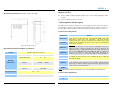
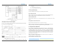
Mechanical Specifications (unit: mm, 1 inch = 25.4 mm)
Driver’s reliable working temperature should be <65 , motor working temperature should
be <80 ;
Forced cooling the driver if it’s necessary.
3. Pin Assignment and Description
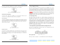
The 22078 has two connectors, connector P1 for control signals connections, and connector P2 for
power and motor connections. The following tables are brief descriptions of the two connectors of
the 22078. More detailed descriptions of the pins and related issues are presented in section 4, 5, 9.
Connector P1 Configurations
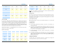
Pin Function
PUL+(+5V)
PUL-(PUL)
Figure 1: Mechanical specifications
DIR+(+5V)
Operating Environment and Other Specifications
Natural Cooling or Forced cooling
Cooling
Environment
DIR-(DIR)
Avoid dust, oil fog and corrosive gases
ENA+(+5V)
Ambient Temperature
- 50
0
ENA+(ENA)
Operating
Environment
40%RH - 90%RH
Humidity
Operating Temperature
70
Max
5.9m/s2 Max
Vibration
READY+
READY-
Details
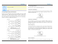
Pulse signal: In single pulse (pulse/direction) mode, this input represents pulse
signal, effective for each rising edge; 4-5V when PUL-HIGH, 0-0.5V when
PUL-LOW. In double pulse mode (pulse/pulse) , this input represents
clockwise (CW) pulse,effective for high level. For reliable response, pulse
width should be longer than 1.2µs. Series connect resistors for current-limiting
when +12V or +24V used.
DIR signal: In single-pulse mode, this signal has low/high voltage levels,
representing two directions of motor rotation; in double-pulse mode (set by
SW5), this signal is counter-clock (CCW) pulse, effective for high level. For
reliable motion response, DIR signal should be ahead of PUL signal by 5µs at
least. 4-5V when DIR-HIGH, 0-0.5V when DIR-LOW. Please note that motion
direction is also related to motor-driver wiring match. Exchanging the
connection of two wires for a coil to the driver will reverse motion direction.
Enable signal: This signal is used for enabling/disabling the driver. High level
for enabling the driver and low level for disabling the driver. Usually left
unconnected (enabled).
Alarm signal positive: READY+ is a photocouper output from open-collector
circuit, effectively output when driver operate normally, maximum permitted
input voltage is 30VDC; maximum output current 20mA. It generally can be
serial connected to PLC input terminal.
Alarm signal negative.
Notes: SW5 ON means CW/CCW (pulse/pulse) mode, and SW5 OFF means PUL/DIR mode.
Storage Temperature
Weight
-20
- 65
Approx. 1.16 kg (41 oz)
Connector P2 Configurations
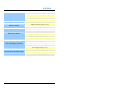
Pin Function
AC
3
Details
AC power supply inputs. Recommend use isolation transformers with