1
EXCELLA
500
600
800
1000
1200
1600
2000
2400
3200
4000
5000
6000
6400
8000
10000
OFF
ON
OFF
ON
OFF
ON
OFF
ON
OFF
ON
OFF
ON
OFF
ON
OFF
ON
OFF
OFF
ON
ON
OFF
OFF
ON
ON
OFF
OFF
ON
ON
OFF
OFF
ON
ON
ON
OFF
OFF
OFF
OFF
ON
ON
ON
ON
OFF
OFF
OFF
OFF
ON
ON
ON
ON
ON
ON
ON
OFF
OFF
OFF
OFF
OFF
OFF
OFF
OFF
EXCELLA
5.55
6.15
6.60
7.20
7.80
3.96
4.39
4.71
5.14
5.57
ON
ON
ON
ON
ON
OFF
ON
ON
ON
ON
ON
OFF
OFF
ON
ON
ON
OFF
ON
OFF
ON
Notes: Due to motor inductance, the actual current in the coil may be smaller than the dynamic
current settings, particularly under high speed condition.
Standstill Current
The 22078 has automatic idle-current reduction function. The current automatically be reduced to
60% of dynamic current setting 0.2 second after the last pulse. Theoretically, this will reduce
motor heating to 36% (due to P=I2 *R) of the original value. If the application needs a different
standstill current, please contact us.
Current Settings
Control Signal Mode Setting
For a given motor, higher driver current will make the motor to output more torque, but at the
same time causes more heating in the motor and driver. Therefore, output current is generally set
to be such that the motor will not overheat for long time operation. Since parallel and serial
connections of motor coils will significantly change resulting inductance and resistance, it is
therefore important to set driver output current depending on motor phase current, motor leads and
connection methods. Phase current rating supplied by motor manufacturer is important in selecting
driver current, however the selection also depends on leads and connections.
SW5 is used for this purpose. SW5 ON means CW/CCW (pulse/pulse) mode, and SW5 OFF
means PUL/DIR mode.
8. Wiring Notes
In order to improve anti-interference performance of the driver, it is recommended to use
twisted pair shield cable.
To prevent noise incurred in pulse/dir signal, pulse/direction signal wires and motor wires
should not be tied up together. It is better to separate them by at least 10 cm, otherwise the
disturbing signals generated by motor will easily disturb pulse direction signals, causing
motor position error, system instability and other failures.
If a power supply serves several drivers, separately connecting drivers is recommended
instead of daisy-chaining.
It is prohibited to pull and plug connector P2 while the driver is powered ON, because there
is high current flowing through motor coils (even when motor is at standstill). Pulling or
plugging connector P2 with power on will cause extremely high back-EMF voltage surge,
which may damage the driver.
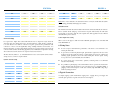
The first three bits (SW6, 7, 8, 9) of the DIP switch are used to set the dynamic current. Select a
setting closest to your motor’s required current.
Dynamic Current Setting
Peak current (A)
0.45
0.63
1.41
1.88
2.33
2.85
3.23
3.75
4.26
4.65
5.18
RMS (A)
0.32
0.45
1.00
1.34
1.66
2.04
2.31
2.68
3.04
3.32
3.70
SW6
OFF
OFF
OFF
OFF
OFF
OFF
OFF
OFF
ON
ON
ON
SW7
OFF
OFF
OFF
OFF
ON
ON
ON
ON
OFF
OFF
OFF
SW8
OFF
OFF
ON
ON
OFF
OFF
ON
ON
OFF
OFF
ON
SW9
OFF
ON
OFF
ON
OFF
ON
OFF
ON
OFF
ON
OFF
9. Typical Connection
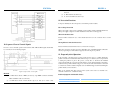
A complete stepping system should include stepping motor, stepping driver, power supply and
controller (pulse generator). A typical connection is shown as figure 9.