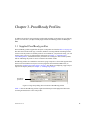
1
ProofMate (ProofReady) Plugin for Epson
Variable Size Droplet (VSD) Printers
Version 1.2r3
November 2007
AG45121 Rev. 8
Copyright and Trademarks
ProofReady Plugin for Epson VSD printers
Version 1.2r3
Part number: HQN-EPSONVSD-1.2r3
Document issue: 109
November 2007
Copyright © 2007 Global Graphics Software Ltd. All rights reserved.
Certificate of Computer Registration of Computer Software. Registration No. 2006SR05517
No part of this publication may be reproduced, stored in a retrieval system, or transmitted, in any form or by any means, electronic, mechanical, photocopying, recording, or otherwise, without the prior written permission of Global Graphics Software
Ltd.
The information in this publication is provided for information only and is subject to change without notice. Global Graphics
Software Ltd and its affiliates assume no responsibility or liability for any loss or damage that may arise from the use of any
information in this publication. The software described in this book is furnished under license and may only be used or copied in accordance with the terms of that license.
Harlequin is a registered trademark of Global Graphics Software Ltd.
The Global Graphics Software logo, the Harlequin at Heart Logo, Cortex, Harlequin RIP, Harlequin ColorPro, EasyTrap,
FireWorks, FlatOut, Harlequin Color Management System (HCMS), Harlequin Color Production Solutions (HCPS),
Harlequin Color Proofing (HCP), Harlequin Error Diffusion Screening Plugin 1-bit (HEDS1), Harlequin Error Diffusion
Screening Plugin 2-bit (HEDS2), Harlequin Full Color System (HFCS), Harlequin ICC Profile Processor (HIPP), Harlequin
Standard Color System (HSCS), Harlequin Chain Screening (HCS), Harlequin Display List Technology (HDLT), Harlequin
Dispersed Screening (HDS), Harlequin Micro Screening (HMS), Harlequin Precision Screening (HPS), HQcrypt, Harlequin
Screening Library (HSL), ProofReady, Scalable Open Architecture (SOAR), SetGold, SetGoldPro, TrapMaster, TrapWorks,
TrapPro, TrapProLite, Harlequin RIP Eclipse Release and Harlequin RIP Genesis Release are all trademarks of Global
Graphics Software Ltd.
Protected by U.S. Patents 5,579,457; 5,808,622; 5,784,049; 5,862,253; 6,343,145; 6,330,072; 6,483,524; 6,380,951;
6,755,498; 6,624,908; 6,809,839.
Other U.S. Patents Pending
Protected by European Patents 0 803 160; 0 772 934; 0 896 771; 672 29 760.8-08.
Portions licensed under U.S. Patent No. 5,212,546; 4,941,038.
TrueType is a registered trademark of Apple Computer, Inc.
The ECI and FOGRA ICC color profiles supplied with this Harlequin RIP are distributed with the kind permission of the ECI
(European Color Initiative) and FOGRA respectively, and of Heidelberger Druckmaschinen AG (HEIDELBERG).
The IFRA ICC profiles supplied with this Global Graphics Software are distributed with the kind permission of IFRA and of
GretagMacbeth.
International Cooperation for Integration of Processes in Prepress, Press and Postpress, CIP4, Job Definition Format, JDF
and the CIP4 logo are trademarks of CIP4.
Adobe, Adobe Photoshop, Adobe Type Manager, Acrobat, Display PostScript, Adobe Illustrator, PostScript, Distiller and
PostScript 3 are either registered trademarks or trademarks of Adobe Systems Incorporated in the United States and/or other
countries which may be registered in certain jurisdictions.
®
Global Graphics Software Ltd is a licensee of Pantone, Inc. PANTONE Colors generated by ScriptWorks are four-color process simulations and may not match PANTONE-identified solid color standards. Consult current PANTONE Color Publications for accurate color. PANTONE®, Hexachrome®, and PANTONE CALIBRATED™ are trademarks of Pantone, Inc. ©
Pantone, Inc., 1991.
Other brand or product names are the registered trademarks or trademarks of their respective holders.
US Government Use
Epson StylusPro software is a computer software program developed at private expense and is subject to the following Restricted Rights Legend: “Use, duplication, or disclosure by the United States Government is subject to restrictions as set forth in (i) FAR 52.227-14 Alt III or (ii) FAR 52.227-19, as applicable. Use by
agencies of the Department of Defense (DOD) is subject to Global Graphics Software’s customary commercial license as contained in the accompanying license
agreement, in accordance with DFAR 227.7202-1(a). For purposes of the FAR, the Software shall be deemed to be ‘unpublished’ and licensed with disclosure
prohibitions, rights reserved under the copyright laws of the United States.” Global Graphics Software Incorporated, 5875 Trinity Parkway, Suite 110, Centreville, VA 2012.
Contents
Chapter 1– Getting Started . . . . . . . . . . . . . . . . . . . . . . . . . . . . . . . . . . . . . . . . . . . . . . . . . . . . . . . . . . . . 1
1.1
Plugin features . . . . . . . . . . . . . . . . . . . . . . . . . . . . . . . . . . . . . . . . . . . . . . . . . . . . . . . . . . . . . . . . 1
1.2
System requirements . . . . . . . . . . . . . . . . . . . . . . . . . . . . . . . . . . . . . . . . . . . . . . . . . . . . . . . . . . . 2
1.5
Enabling the printer plugin . . . . . . . . . . . . . . . . . . . . . . . . . . . . . . . . . . . . . . . . . . . . . . . . . . . . . . 6
1.7
Allocating additional memory to the RIP . . . . . . . . . . . . . . . . . . . . . . . . . . . . . . . . . . . . . . . . . . . 9
1.8
Related documentation . . . . . . . . . . . . . . . . . . . . . . . . . . . . . . . . . . . . . . . . . . . . . . . . . . . . . . . . 10
Chapter 2– Output Devices . . . . . . . . . . . . . . . . . . . . . . . . . . . . . . . . . . . . . . . . . . . . . . . . . . . . . . . . . . .
2.1
Epson output devices . . . . . . . . . . . . . . . . . . . . . . . . . . . . . . . . . . . . . . . . . . . . . . . . . . . . . . . . . .
2.2
Setting device options . . . . . . . . . . . . . . . . . . . . . . . . . . . . . . . . . . . . . . . . . . . . . . . . . . . . . . . . .
2.3
Adding new output devices . . . . . . . . . . . . . . . . . . . . . . . . . . . . . . . . . . . . . . . . . . . . . . . . . . . . .
2.4
Halftone screen selection . . . . . . . . . . . . . . . . . . . . . . . . . . . . . . . . . . . . . . . . . . . . . . . . . . . . . . .
11
11
13
19
20
Chapter 3– ProofReady Profiles . . . . . . . . . . . . . . . . . . . . . . . . . . . . . . . . . . . . . . . . . . . . . . . . . . . . . . . 23
3.1
Supplied ProofReady profiles . . . . . . . . . . . . . . . . . . . . . . . . . . . . . . . . . . . . . . . . . . . . . . . . . . . 23
Chapter 4– Creating Page Setups . . . . . . . . . . . . . . . . . . . . . . . . . . . . . . . . . . . . . . . . . . . . . . . . . . . . . . 31
4.1
Creating a page setup. . . . . . . . . . . . . . . . . . . . . . . . . . . . . . . . . . . . . . . . . . . . . . . . . . . . . . . . . . 31
4.2
Page layout options . . . . . . . . . . . . . . . . . . . . . . . . . . . . . . . . . . . . . . . . . . . . . . . . . . . . . . . . . . . 33
Chapter 5– Calibration and Color Management . . . . . . . . . . . . . . . . . . . . . . . . . . . . . . . . . . . . . . . . . .
5.1
Calibrating the printer . . . . . . . . . . . . . . . . . . . . . . . . . . . . . . . . . . . . . . . . . . . . . . . . . . . . . . . . .
5.2
Recalibrating . . . . . . . . . . . . . . . . . . . . . . . . . . . . . . . . . . . . . . . . . . . . . . . . . . . . . . . . . . . . . . . .
5.3
Creating an ICC profile and installing in the RIP . . . . . . . . . . . . . . . . . . . . . . . . . . . . . . . . . . . .
5.4
Creating ColorPro profiles. . . . . . . . . . . . . . . . . . . . . . . . . . . . . . . . . . . . . . . . . . . . . . . . . . . . . .
35
35
37
37
40
Appendix 6– Output File Naming . . . . . . . . . . . . . . . . . . . . . . . . . . . . . . . . . . . . . . . . . . . . . . . . . . . . . .
6.1
Content generating tags . . . . . . . . . . . . . . . . . . . . . . . . . . . . . . . . . . . . . . . . . . . . . . . . . . . . . . . .
6.2
Checking tags. . . . . . . . . . . . . . . . . . . . . . . . . . . . . . . . . . . . . . . . . . . . . . . . . . . . . . . . . . . . . . . .
6.3
Examples of tag usage . . . . . . . . . . . . . . . . . . . . . . . . . . . . . . . . . . . . . . . . . . . . . . . . . . . . . . . . .
43
43
45
45
Appendix 7– Post processing . . . . . . . . . . . . . . . . . . . . . . . . . . . . . . . . . . . . . . . . . . . . . . . . . . . . . . . . . . 51
7.1
Post processing substitution codes. . . . . . . . . . . . . . . . . . . . . . . . . . . . . . . . . . . . . . . . . . . . . . . . 51
7.2
Checking the command string . . . . . . . . . . . . . . . . . . . . . . . . . . . . . . . . . . . . . . . . . . . . . . . . . . . 53
Appendix 8– Memory Requirements. . . . . . . . . . . . . . . . . . . . . . . . . . . . . . . . . . . . . . . . . . . . . . . . . . . . 55
8.1
Determining processing overhead . . . . . . . . . . . . . . . . . . . . . . . . . . . . . . . . . . . . . . . . . . . . . . . . 55
8.2
Memory factor tables . . . . . . . . . . . . . . . . . . . . . . . . . . . . . . . . . . . . . . . . . . . . . . . . . . . . . . . . . . 57
Appendix 9 – Troubleshooting . . . . . . . . . . . . . . . . . . . . . . . . . . . . . . . . . . . . . . . . . . . . . . . . . . . . . . . . . 61
9.1
RIP Monitor windows output messages . . . . . . . . . . . . . . . . . . . . . . . . . . . . . . . . . . . . . . . . . . . 61
9.2
Problems with passwords. . . . . . . . . . . . . . . . . . . . . . . . . . . . . . . . . . . . . . . . . . . . . . . . . . . . . . . 74
Chapter 1–Getting Started
This manual describes the Epson Stylus Pro VSD printer plugin for the Harlequin RIP and is
suitable for the following Epson printers:
•
Stylus Pro 4000
•
Stylus Pro 5500
•
Stylus Pro 7600
•
Stylus Pro 9600
•
Stylus Pro 10000
•
Stylus Pro 10600
•
Stylus Photo 2200 and 2100
The plugin adds new output devices to the Harlequin RIP for use in your page setups. Each
™
device provides support for a variety of inking regimes and Harlequin ProofReady profiles,
which provide expert, “out the box” color management for printing proofs.
1.1 Plugin features
These Epson printers are capable of delivering prints with amazing color fidelity, gloss-level,
and scratch resistance. The plugin has been engineered to support the full range of inks maintained by the printer, including 6 or 7-color inks (depending on printer type), and two black
inks.
Briefly, the plugin has the following features:
•
A selection of Harlequin RIP plugin devices for outputting to the Epson Stylus Pro 4000
VSD printer series.
•
A selection of ProofReady color management profiles, each designed to produce outstanding results on a range of commonly used papers and inks.
•
Support for HEDS1 and HEDS2, Global Graphics’ advanced screening technology.
AG45121 Rev. 8
1
1.2 System requirements
The following components are needed to install and run the Epson plugin.
1.2.1 Windows XP and Windows Vista
These are the platform requirements for a Windows operating system.
®
®
•
Intel Pentium 4 1 GHz (or equivalent).
•
Microsoft Windows 2000 (SP 2), Windows XP Professional or Home Edition. and Windows Vista.
•
256 MB of RAM (512 MB recommended for variable sized dot devices).
®
1.2.2 Apple Mac
These are the platform requirements for a Mac OS X operating system.
®
•
Intel Mac and PowerPC G4.
•
Mac OS X v.10.4.x.
•
256 MB of RAM with virtual memory turned on (128 MB recommended).
®
1.2.3 Linux
These are the platform requirements for a Linux operating system.
•
Intel Pentium 4 1 GHz (or equivalent).
•
Red Hat Enterprise Linux ES v4.0 or v5.0.
Note: For each of these platforms, configure the Harlequin RIP with at least 4 MB RAM for
the printer buffer and 24 MB RAM for the system. See “Allocating additional memory to the
RIP” on page 9 for details of how to do this.
1.2.4 Memory and disk space requirements
The following minimum system requirements are needed to run the Epson plugin successfully:
2
•
128 MB RAM.
•
1 GB disk space (additional space may be required for large format or high-resolution
output).
•
For large format or high-resolution jobs, in the Configure RIP dialog box, increase the
Printer buffer setting to at least 20000 KB and Disk space left for system to 20 MB.
AG45121 Rev. 8
For a precise method of determining the amount of memory required by the RIP when processing jobs for the Epson, see Appendix 8, “Memory Requirements”.
1.2.5 Supported RIPs
The Epson plugin has been approved for use with the following RIPs:
•
Harlequin RIP v7.2 Genesis Release.
•
Harlequin RIP v8.0 Release.
1.2.6 Optional items
Depending on how you want to process your print jobs, the following optional items may also
be needed:
™
™
•
Harlequin ColorPro —required for Harlequin RIP ProofReady color management
technology.
•
HEDS, HEDS1 and/or HEDS2—required for Harlequin Error Diffusion Screening
(HEDS) technology.
•
HDS or HDS Light screens—required for Harlequin Dispersed Screening (HDS) technology.
Your Harlequin RIP supplier will be able to provide you with necessary serial numbers to
enable these features in the RIP.
1.3 Installing plugins with the RIP
This section describes how to add plugins, either at the same time as the RIP is installed, or in
a subsequent installation.
The InstallAnywhere installer allows you to easily install the Harlequin RIP products contained on the CD. Instructions for installation can also be found in the install.htm file in the
directory above the Install_xx file (where xx is the customer name abbreviation). Detailed
instructions for installing the Harlequin RIP on Windows, Mac and Unix platforms can be
found in the Harlequin RIP Installation Guide. To ensure you have the necessary privileges for
installing the Harlequin RIP, you may have to log on as System Administrator.
1.
Insert the Harlequin RIP CD-ROM and open it. Double-click the Install_xx file to load
the InstallAnywhere package. See the Installing the Harlequin RIP for Linux manual for
details of the install processs on a Linux platform.
AG45121 Rev. 8
3
1.
Follow the InstallAnywhere screen instructions. Select the Next button to move onto the
next screen and the Previous button to return to a previous screen. Every step of the install
procedure is shown in the left hand window.
Figure 1.1 InstallAnywhere dialog
4
AG45121 Rev. 8
2.
The “Choose Features” screen shows all the products available in the package. When you
select a product, a short description of its function appears. Those products not checked in
the list will not be installed.
Figure 1.2 InstallAnywhere Choose Features dialog
Note: Use the scroll bar at the right side of the display to view more selection options.
3.
Use the “Choose Install Folder” screen to select an installation folder. If you wish you can
choose a different install folder to the default. Click Choose... and navigate to the required
folder. If at any time you wish to restore the default location click Restore Default Folder.
Click Next to move onto the next stage and install in the desired location.
4.
On Windows platforms the “Choose Shortcut Folder” screen allows you to create any
icons or Start menu options for the Harlequin RIP. When this is done click Next.
5.
The “Pre-installation Summary” screen allows you to examine your installation choices.
If required, use the Previous button to return to earlier screens and modify your selections,
otherwise click Install to proceed with the installation.
AG45121 Rev. 8
5
6.
A warning dialog may be displayed at his point. Any products on your system that use the
Harlequin License Server should be stopped before continuing with the installation. Click
Continue to move ahead with the installation. Previous versions of the HLS will now be
removed.
7.
The “Install Complete” screen indicates that the installer has finished. If any errors have
occurred a message will be displayed. Click Done to exit from the installer. You can view
the details of the errors by opening the xx_InstallLog.xml file which is located in the installation folder.
1.4 Installing plugins separately
1.
Follow the InstallAnywhere screen instructions as before. Select the Next button to move
onto the next screen and the Previous button to return to a previous screen.
2.
The “Choose Features” screen shows all the products available in the package. When you
select a product, a short description of its function appears. Select only the plugins that
you wish to install. Those products not checked in the list will not be installed.
3.
On Windows systems in the “Choose Install Folder” screen select the same installation
folder as the previously installed RIP. Click Next to move onto the next stage.
4.
At the “Pre-installation Summary” screen click Install to proceed with the installation.
5.
The installation will now continue. This may take some minutes.
6.
The “Install Complete” screen indicates that the installer has finished. If any errors have
occurred a message will be displayed. Click Done to exit from the installer. You can view
the details of the errors by opening the xx_InstallLog.xml file which is located in the installation folder.
1.5 Enabling the printer plugin
The Epson plugin needs to be enabled in the Harlequin RIP before it can be used, along with
related plugins for screening and color management, unless you have already preset a key, in
which case the plugin will already be enabled.
1.
6
Start the Harlequin RIP. Choose Harlequin RIP > Configure RIP (or CTRL+R) to open
the Configure RIP dialog. Click Extras to open the Configure RIP Extras dialog
(Figure 1.3).
AG45121 Rev. 8
Figure 1.3 The Configure RIP Extras dialog
2.
To enable a plugin from the list available, you must enter a password as supplied by your
Harlequin RIP supplier.
3.
Select the plugin that you wish to add and click Add... the Enable Feature dialog box is
displayed. Enter the supplied password in the dialog box and click OK.
Figure 1.4 Enabling RIP features
4.
Click OK the close the Configure RIP Extras dialog, and then click OK to close the Configure RIP dialog.
The features will now be enabled in the RIP and may be used in your page setups to process
jobs, as described in Chapter 4, “Creating Page Setups”.
AG45121 Rev. 8
7
1.5.1 Screening plugin compatibility
The Epson VSD printer plugin is compatible with the following plugins:
•
HEDS1, HEDS2: version 2.1( for 7.x RIPs)
•
HEDS: v3 (for v8.0 and later RIPs)
1.5.2 Installing screening plugins
HEDS screenin plugins must be installed and enabled in the Harlequin RIP before they can be
used.
Depending on which device you choose to use the plugin uses a default screening method, as
follows:
•
1-bit single dot size devices (SD)—HDS Super Fine screening
•
2-bit variable dot size devices (VSD)—HEDS2 screening
Other screening methods are possible when using SD devices, for example, HDS
Fine/Medium/Coarse/Super Coarse orHEDS1.
To use a different screen requires you to configure the separation style sheet.
To use any of these screening methods the relevant screening plugin(s) must be installed and
enabled in the Harlequin RIP. Failure to do this will cause the RIP to use Euclidean screening
instead in the case of 1-bit devices, or, in the case of 2-bit devices, may cause the RIP to freeze
or unexpectedly quit. The following versions of the screening plugins are compatible with the
ProofReady plugin:
•
HEDS1 and HEDS2: version 2.1.1 or later (for 7.x RIPs)
•
HEDS v3 (for Harlequin v8.0 RIP and later)
HDS screens are automatically installed with the RIP and just need to be enabled, however
HEDS1 and HEDS2 must be installed and enabled separately, as described in the next section.
In addition to the screening plugins, the screening plugin requires a color management option,
such as Harlequin ColorPro™ to be enabled.
1.6 Location of plugin folders
Table 1 shows the correct Harlequin RIP installation folders for the Epson VSD printer plugin
and supplied screening plugins. This information is provided for reference only. Unless
instructed by Technical Support, you should not move these folders or delete information contained in them or the plugins may cease to function correctly.
8
AG45121 Rev. 8
Source folder
Description
Destination folder
\epsonvsd\
Epson VSD printer
plugin
…\<RIP-folder>\SW\Devices\
\HEDS1\
HEDS1 screening
…\<RIP-folder>\SW\Screenin
\HEDS1\ExtraStart\HEDS1Init\
\HEDS2\
…\<RIP-folder>\SW\Sys\ExtraStart
HEDS2 screening
\HEDS2\ExtraStart\HEDS2Init\
\HEDS\
…\<RIP-folder>\SW\Screenin
…\<RIP-folder>\SW\Sys\ExtraStart
HEDS1+HEDS2
screening
…\<RIP-folder>\SW\Extensions \Core
Module\heds
Table 1 Default installation folders for supplied plugins
1.7 Allocating additional memory to the RIP
To process jobs with the Epson plugin you may need to allocate additional memory to the RIP
printer buffer. The precise amount of memory required depends upon the nature of the job to
be processed. Large, high quality jobs will require more memory than small, low quality jobs.
The basic memory requirements for the RIP is to provide sufficient memory to prevent the
operating system from page buffering, which has the undesired effect of slowing the RIP
down. At the other end of the scale, the more memory you can make available to the RIP the
better it will process the job. Figures of 500 MB and above may be needed to process some
large jobs, especially if options such as in-RIP trapping and screening are being used. In general, the more memory the RIP has available to use, the better it performs.
To set the printer buffer memory allocation, open the Configure RIP dialog (Figure 1.5) and
enter a value into the Printer Buffer box. Suggested settings are:
•
Low/medium resolution prints on standard size pages: 20000 KB
•
High resolution prints on standard size pages: 40000 KB
•
Low/medium resolution prints on large size pages: 40000 KB
•
High resolution prints on large size pages: 60000+ KB
AG45121 Rev. 8
9
Any other RIP memory settings should be configured according to the recommendations given
in your Harlequin RIP User Manual, since these vary according to the RIP release you are running.
Figure 1.5 Setting the printer buffer size in the RIP
See also, Appendix 8, “Memory Requirements” for more information on the specific memory
requirements of the plugin.
1.8 Related documentation
For more details about the printer you are using, see the manufacturer’s documentation supplied with the printer or the relevant product support section of the manufacturer’s web site.
For more information on installing the Harlequin RIP, see the Harlequin RIP Installation
Manual.
For more information about the RIP, see the RIPMate User Guide.
™
For more information about Harlequin ColorPro, see the Harlequin ColorPro User’s Guide.
10
AG45121 Rev. 8
Chapter 2–Output Devices
The Epson VSD printer plugin adds several new output devices to the RIP. Select the device
you wish to use in your page setup, and the RIP will process jobs for the Epson VSD printer
plugin using the correct device settings for ink, media type, and output quality.
2.1 Epson output devices
Table 2.1 lists the Harlequin RIP output devices that are available in the page setup area of the
RIP after installing the Epson VSD printer plugin.
Device
Usage
SP2200 Roll
Produces output for roll-fed paper using fixed sized ink
dots, which can be small, medium or large.
SP2200 Sheet
Produces output for sheet-fed paper using fixed sized ink
dots, which can be small, medium or large.
SP2200 VSD Roll
Produces output for roll-fed paper using varying sized ink
dots.
SP2200 VSD Sheet
Produces output for sheet-fed paper using varying sized
ink dots.
SP4000 Roll
Produces output for roll-fed paper using fixed sized ink
dots, which can be small, medium or large.
SP4000 Sheet
Produces output for sheet-fed paper using fixed sized ink
dots, which can be small, medium or large.
SP4000 VSD Roll
Produces output for roll-fed paper using varying sized ink
dots.
SP4000 VSD Sheet
Produces output for sheet-fed paper using varying sized
ink dots.
Table 2.1 Epson VSD devices
AG45121 Rev. 8
11
Device
Usage
SP7600 Roll
Produces output for roll-fed paper using fixed sized ink
dots, which can be small, medium or large.
SP7600 Sheet
Produces output for sheet-fed paper using fixed sized ink
dots, which can be small, medium or large.
SP7600 VSD Roll
Produces output for roll-fed paper using varying sized ink
dots.
SP7600 VSD Sheet
Produces output for sheet-fed paper using varying sized
ink dots.
SP9600 Roll
Produces output for roll-fed paper using fixed sized ink
dots, which can be small, medium or large.
SP9600 Sheet
Produces output for sheet-fed paper using fixed sized ink
dots, which can be small, medium or large.
SP9600 VSD Roll
Produces output for roll-fed paper using varying sized ink
dots.
SP9600 VSD Sheet
Produces output for sheet-fed paper using varying sized
ink dots.
SP10600 Roll
Produces output for roll-fed paper using fixed sized ink
dots, which can be small, medium or large.
SP10600 Sheet
Produces output for sheet-fed paper using fixed sized ink
dots, which can be small, medium or large.
SP10600 VSD Roll
Produces output for roll-fed paper using varying sized ink
dots.
SP10600 VSD Sheet
Produces output for sheet-fed paper using varying sized
ink dots.
SP5500 Roll
Produces output for roll-fed paper using fixed sized ink
dots, which can be small, medium or large.
SP5500 Sheet
Produces output for sheet-fed paper using fixed sized ink
dots, which can be small, medium or large.
SP5500 VSD Roll
Produces output for roll-fed paper using varying sized ink
dots.
Table 2.1 Epson VSD devices
12
AG45121 Rev. 8
Device
Usage
SP5500 VSD Sheet
Produces output for sheet-fed paper using varying sized
ink dots.
SP10000 Roll
Produces output for roll-fed paper using fixed sized ink
dots, which can be small, medium or large.
SP10000 Sheet
Produces output for sheet-fed paper using fixed sized ink
dots, which can be small, medium or large.
SP10000 VSD Roll
Produces output for roll-fed paper using varying sized ink
dots.
SP10000 VSD Sheet
Produces output for sheet-fed paper using varying sized
ink dots.
Table 2.1 Epson VSD devices
Each device also has a selection of Harlequin ProofReady profiles for instant color management. See “Calibration and Color Management” on page 25 for a list of ProofReady profiles
that are available.
2.2 Setting device options
The devices installed by the Epson VSD printer plugin can be configured to suit your particular job processing requirements. For instance, you can change the media and ink types to suit
those installed in your printer, change the output quality to increase throughput or print quality,
and add post-processing commands which run after the job has been processed.
The device options are accessed via the Configure Device dialog (Figure 2.1), by clicking
Configure device in a page setup. Any changes you make to a device remain local to the particular page setup they were made in and do not effect other page setups. This means you can
AG45121 Rev. 8
13
have multiple page setups for the same output device, each with different device settings to suit
your job processing needs.
Figure 2.1 The Configure Device dialog
The following device processing options are available:
Output method
Used to specify the output method for the job. Some output methods (for instance, LPT1) are
only available if the operating system supports it. The following options are available:
File
Outputs to the disk location that is specified in File Output,
using the file template options (if any) that are specified in
File template. This is the default output method for the plugin.
Network
Outputs to the printer whose IP address and port number are
specified in the Network Output settings. The printer must be
fitted with a suitable network interface card (NIC) for this
option to work.
LPT1
Windows only. Outputs to the printer attached to the parallel
port on the RIP machine.
USB:<printer model>
Outputs to the printer which is connected via USB to the RIP
machine. Where <printer model> is the model name
returned by the printer. Note that a printer will only appear
when the host USB subsystem has acknowledged its presence.
14
AG45121 Rev. 8
SPL:<printer name>
Where <printer name> is the name by which the printer is
known to Windows. The plugin outputs data via the Windows
printer spooler, offering the possibility of outputting to connection methods not directly supported by the plugin, such as
Firewire.
File Output
Used to specify a location for the output file. By default it is the RIP’s SW folder, but you may
choose any valid location on your system or network.
File template
Used to enter a file naming template for the processed jobs. By default the file naming template is: <dos>out<5unique><dot>epf, which creates a file name that is cross platform (8.3
file name) and is suitable for multi-page jobs. See Appendix 6, “Output File Naming” for more
information on using file naming templates.
IP address
Used to specify the network IP address or resolved name of the printer.
Port number
The TCP/IP port number used by the device to accept print jobs. If you have installed a 10/100
Base-T type B Ethernet card the Port Number should be set to 515, unless you are using an
Epson 10/100 Base TX Internal Print Server 2 interface card (C12C823914), or later, in which
case you can set it to 9100, for bidirectional communication. If sending output to a single
printer using a JetDirect unit the Port Number must be set to 9100.
Some print servers can drive several printers simultaneously and the different physical connections or ports have their own numbers (which may vary with the type of server). For example,
on a JetDirect unit with three output ports, the physical ports named 1, 2, and 3 have port
numbers 9100, 9101, and 9102 respectively.
For genuine Epson network interface cards the following ports are commonly available:
9100
Used for raw (no protocol), binary and bidirectional
communications.
515
Used for lpr-protocol, binary and unidirectional
commumications.
For non-Epson network print servers consult the relevant documentation, but note that port 515
is less likely to work with non-Epson interfaces.
AG45121 Rev. 8
15
Media type
Used to specify the media that is installed in the printer.
Note: This setting can be overridden by the Profile Hook associated with a selected ProofReady profile.
Ink type
Used to specify the ink type that is installed in your Epson printer. Your printer manual should
be able to advise you on the correct ink type to use for the paper you are using.You must
choose the correct ink type, otherwise an error message will be generated and you will not be
able to print (except on the Stylus Photo 2200, which is unable to recognize when an incorrect
ink type is selected).
Epson Stylus Pro 5500
the Archival (pigment) ink option is automatically
selected and cannot be changed because this printer only supports pigment-based ink sets.
Epson Stylus Pro 10600
Options include UltraChrome (PhotoK) and
UltraChrome (MatteK), which correspond to the two black
™
ink modes available when using an UltraChrome ink set
with this device: Photo Black mode (optimized for photographic and ink jet coated media types) and Matte Black mode
(optimized for matte or plain media).
Epson Stylus Pro 7600/9600
Options include UltraChrome (PhotoK+LightK),
UltraChrome (MatteK+LightK), and UltraChrome
(MatteK*2), which correspond to the three black ink modes
™
available when using an UltraChrome ink set with this
device: Photo Black mode (optimized for photographic and
ink jet coated media types); Matte Black mode (optimized for
matte or plain media, where quality is favored over print
speed).
If your printer is one that provides a choice of ink type, the type or combination your printer is
using should be selected in the Ink Type menu from one of:
16
Dye ink
Photographic Dye
Archival (pigment) ink
Archival/ColorFast
AG45121 Rev. 8
UltraChrome ink
UltraChrome, using the default or only variation. The
default, unless otherwise stated, is Photo Black for singleblack devices, Photo Black with Light Black for dual-black
devices.
UltraChrome
(PhotoK+LightK)
UltraChrome using Photo Black with Light Black
UltraChrome
(MatteK+LightK)
UltraChrome using Matte Black with Light Black
UltraChrome (MatteK*2)
UltraChrome using 2 Matte Blacks
UltraChrome (PhotoK)
UltraChrome using Photo Black on its own
UltraChrome (MatteK)
UltraChrome using Matte Black on its own.
The exact list of options is device dependent, see “Setting device options” on page 13 for more
information.
ProofReady profiles supplied by Global Graphics use a prefix to the profile name to differentiate, for printers supporting more than one type of ink, the ink type selection which must be
used for the profile.
The prefixes for devices supporting more than one major ink type are:
Arc
Archival (pigment) ink
Dye
Dye ink
Ucm
UltraChrome (PhotoK) or UltraChrome (PhotoK+LightK)
UcmMkLK
UltraChrome (MatteK+LightK)
UcmMk
UltraChrome (MatteK) or UltraChrome (MatteK*2) for
dual-black printers.
For example:
Arc Enhanced Matte 720
Dye Pres Matte 720
Ucm Prem SemiGloss 720
The prefixes for devices only supporting UltraChrome ink (such as the Stylus Photo 2200) are:
MkLk
UltraChrome (MatteK+LightK)
Mk
UltraChrome (MatteK) or UltraChrome (MatteK*2) for
dual-black printers
AG45121 Rev. 8
17
For example:
Premium Glossy 720
MkLk Enhanced Matte 720
Most professional series printers will reject a job (see "Command error..." error message, as
documented in “Printer messages” on page 61) if the ink type used when the job was processed
by the RIP does not match the inks loaded in the printer. The plugin also tries to query the ink
type where possible, in order to avoid sending a job of the wrong type to the printer (see “The
selected ink type is incorrect...” “Printer messages” on page 61).
Paper feed adjustment offset
Enter a value in the range between -70 and +70 to control the rate of feed of the paper for your
particular printer. The default value is zero. Positive values increase the rate of feed to reduce
dark banding. Negative values decrease the rate of feed to reduce white banding.
Quality
Used to specify the overall output quality of the job. For excellent quality, choose “Enhanced
Microweave”, for faster printing (but lower quality) choose “Faster Microweave”. For good
quality/speed use “Standard Microweave”. Use “Printer Microweave” to let the printer handle
the microweave processing, if it can.
Compression
Used to specify the compression mode for data that is delivered to the printer. The available
options are as follows:
None
Data is sent raw (uncompressed). Can result in longer print
times.
Run length
Data is sent compressed, which often reduces the transmission
time and hence speeds up printing.
Paper size
This option is not enabled. Instead, use the options in the Page Layout dialog to specify the
paper size, as described in “Page, media and paper size” on page 34.
Paper bin
This option is not available for the Epson VSD printer plugin.
Cut paper at end of each page
If using a roll-fed device, select this option to have the printer cut the paper at the end of each
page. This option will be overridden by the printer if paper cutting is not enabled in the printer.
18
AG45121 Rev. 8
Bidirectional printing
Select this option to use bidirectional printing, which allows the print head to print both when
moving left to right and when moving right to left, thus speeding up printing. Be sure to check
the output quality when bidirectional printing is being used.
Post processing:
Use the panel options to set up your post processing options. You may enter any command that
can be run from a command line, and use the substitution codes listed in Appendix 7, “Post
processing” to pass parameters to the command for executing. Note that Enable must be
selected before the commands will execute.
Note: Windows commands interpreted by cmd.exe, such as echo, cannot be run directlty, and
should be incuded in a batch file.
2.3 Adding new output devices
The Harlequin RIP printer plugins supplied by Global Graphics often contain devices for more
than one type of printer model. To limit the device list, however, only a single set of devices is
added to the device list when a printer is enabled in the RIP. To add other devices you must add
them manually, one at a time, as described next.
1.
Open the Harlequin RIP Device Manger, by choosing Harlequin RIP > Device Manager.
2.
From the plugin list, select the correct plugin.
3.
Click New to open Device Manager Edit.
4.
Enter the following details:
5.
Name
A name for the device. This should match the device name
(including the use of upper and lower case letters).
Type
Choose a type from the list.
Address
Leave blank.
Click OK to apply these settings.
The new device will be created and will appear in the list of devices available for selection in a
page setup.
2.4 Halftone screen selection
The Harlequin RIP supplies halftone screens of various types for use with printers which support six, seven, eight or more inks. Screen selection is largely an automatic choice determined
AG45121 Rev. 8
19
by the selected device. In particular, you should not change the default screening method when
using ProofReady profiles as this will certainly affect the print quality.
A detailed explanation of the screens which are available and what effect they have on printed
output is beyond the scope of this manual, but a brief description for each screening method is
given below.
HEDS 1
This is one of the in-RIP EDS screens used to produce the
supplied profiles for 1-bit (single dot) device types. To use
this screen, the HEDS1 screening plugin must be installed and
enabled, as described in “Screening plugin compatibility” on
page 8.
HEDS 2
This is one of the in-RIP EDS screens used to produce the
supplied profiles for 2-bit (variable size dot) device types. To
use this screen, the HEDS2 screening plugin must be installed
and enabled, as described in “Screening plugin compatibility”
on page 8.
HDS Super Fine (HDS SF)
This is one of the screens used to produce the supplied profiles for biplane device types. If using a supplied profile based
on this screen, ensure that this option is selected from the Edit
Style dialog box accessed from the Separations Manager. This
screen is only available for use with biplane or 1-bit (single
dot) device types.
HDS Fine
This is an alternative to HDS Super Fine, producing a coarser
screen than HDS Super Fine. This screen is only available for
use with biplane or 1-bit (single dot) device types.
HDS Medium
HDS Coarse
HDS Super Coarse
The Medium, Coarse, and Super Coarse variants of HDS are
only recommended as special effects screens. These screens
are only available for use with biplane or 1-bit device types.
Chain
20
This screen is only available for use with biplane or 1-bit
device types.
AG45121 Rev. 8
AG45121 Rev. 8
21
22
AG45121 Rev. 8
Chapter 3–ProofReady Profiles
To address the needs of print production professionals and their requirement for great looking
proofs “out of the box”, the Epson VSD plugin includes ProofReady profiles for Harlequin
RIPs.
3.1 Supplied ProofReady profiles
The ProofReady profiles supplied for the Epson VSD printer are listed in Table 3.1on page 24.
The table also lists the media type, resolution, halftone screening method and inking scheme
used to create the profile. If a suitable profile is not available for your particular setup, you will
need to create your own, by following the instructions in Chapter 5, “Calibration and
Color Management”, which describes the procedures for creating ICC and ColorPro profiles
and for calibrating the printer to ensure consistent and reliable results.
ProofReady profiles are available for selection in a page setup once a device that supports them
has been selected and the Harlequin ColorPro plugin has been enabled in RIP Extras, as
described in “Enabling the printer plugin” on page 6. For details on configuring a page setup to
output to the Epson printer, see Chapter 4, “Creating Page Setups”.
ProofReady
profiles list
Figure 3.1 Page Setup dialog shown location of ProofReady profiles
Table 3.1 lists the ProofReady profiles supplied with the Epson VSD plugin and shows the
screening method used to create each profile..
AG45121 Rev. 8
23
.
Table 3.1 Epson VSD ProofReady profiles
ProofReady Profile
(Device name)
Paper (part no.)
Screening
Premium Gloss (S041286)
HEDS2
Premium Semi-Gloss
(S041331)
HEDS2
Enhanced Matte (S041341)
HEDS2
Epson Enhanced Matte
Paper (SO41725)
HDS Super Fine
Epson Premium Glossy
Photo Paper 250g
(SO41315)
HDS Super Fine
Epson Enhanced Matte
Paper (SO41725)
HEDS2
Mitsubishi Newsprint
HEDS2
Epson Premium Glossy
Photo Paper 250g
(SO41315)
HEDS2
Epson Premium Luster
Photo Paper 250g
(S041737)
HEDS2
Epson Proofing Paper SemiMatte (SO41724)
HEDS2
Epson 2200
Premium Glossy 720/1440
(SP2200 VSD)
Premium SemiGloss 720/1440
(SP2200 VSD)
MkLk Enhanced Matte 720/1440
(SP2200 VSD)
Epson 4000
Enhanced Matte 360
(SP4000)
Premium Glossy 250g 2880
(SP4000)
Enhanced Matte 720/1440
(SP4000 VSD)
Mitsu PRN Newsprint 720
(SP4000 VSD)
Premium Glossy 250g 720/1440
(SP4000 VSD)
Premium Luster 250g 720
(SP4000 VSD)
SemiMatte Proof 720/1440
(SP4000 VSD)
24
AG45121 Rev. 8
Table 3.1 Epson VSD ProofReady profiles (Continued)
ProofReady Profile
(Device name)
SWOP-cert SemiMatte Proof
(SP4000 VSD) See “Notes on the
profiles” on page 29 below.
Paper (part no.)
Screening
Epson Proofing Paper SemiMatte (SO41724)
HEDS2
Epson Archival Matte Paper
(SO41339)
HDS Super Fine
Epson Premium Semigloss
Photo Paper (SO41327)
HDS Super Fine
Epson Professional Glossy
Paper (SO41430)
HDS Super Fine
Epson Archival Matte Paper
(SO41340)
HEDS2
Epson Premium SemiGloss
Photo Paper (S041328)
HEDS2
Epson Professional Glossy
Paper (SO41457)
HEDS2
Epson Enhanced Matte
Paper (S041595)
HEDS1
Epson Premium Glossy
Photo Paper (250)
(S041638)
HDS Super Fine
Epson Glossy Paper Photo
Weight (S041388)
HEDS1
Epson SemiMatte Proofing
Paper (S041658)
HEDS1
Epson 5500
Archival Matte 720
(SP5500 VSDbi)
Premium SemiGloss 720
(SP5500 VSDbi)
Pro Glossy 720
(SP5500 VSDbi)
Archival Matte 720/1440
(SP5500 VSD)
Premium SemiGloss 720/1440
(SP5500 VSD)
Pro Glossy 720/1440
(SP5500 VSD)
Epson 7600
Ucm Enhanced Matte 2880
(SP7600)
Ucm Premium Glossy 250g 2880
(SP7600)
Ucm Glossy Photo Wt 2880
(SP7600)
Ucm SemiMatte Proof 2880
(SP7600)
AG45121 Rev. 8
25
Table 3.1 Epson VSD ProofReady profiles (Continued)
ProofReady Profile
(Device name)
Dye Glossy Paper Hvy 720
(SP7600 VSD)
Dye Pres Matte 720
(SP7600 VSD)
Dye SemiGloss Hvy 720
(SP7600 VSD)
Ucm Enhanced Matte 720/1440
(SP7600 VSD)
Ucm Glossy Photo Wt 720
(SP7600 VSD)
Ucm Premium Glossy 250g 720/1440
(SP7600 VSD)
Ucm SemiMatte Proof 720/1440
(SP7600 VSD)
Paper (part no.)
Screening
Epson Glossy Hvy Wt
(S041291)
HEDS2
Epson Presentation Matte
(S041295)
HEDS2
Epson Semi-Gloss Hy Wt
(S041292)
HEDS2
Epson Enhanced Matte
Paper (S041595)
HEDS2
Epson Glossy Paper Photo
Weight (SO41388)
HEDS2
Epson Premium Glossy
Photo Paper (250)
(S041638)
HEDS2
Epson SemiMatte Proofing
Paper (S041658)
HEDS2
Epson Enhanced Matte
Paper (S041595)
HEDS1
Epson Glossy Paper Photo
Weight S041388
HEDS1
Epson Premium Glossy
Photo Paper (250)
(S041638)
HDS Super Fine
Epson SemiMatte Proofing
Paper S041658
HEDS1
Epson Glossy Hvy Wt
(S041291)
HEDS2
Epson 9600
Ucm Enhanced Matte 2880
(SP9600)
Ucm Glossy Photo Wt 2880
(SP9600)
Ucm Premium Glossy 250g 2880
(SP9600)
Ucm SemiMatte Proof 2880
(SP9600)
Dye Glossy Paper Hvy 720
(SP9600 VSD)
26
AG45121 Rev. 8
Table 3.1 Epson VSD ProofReady profiles (Continued)
ProofReady Profile
(Device name)
Dye Pres Matte 720
(SP9600 VSD)
Dye SemiGloss Hvy 720
(SP9600 VSD)
Ucm Enhanced Matte 720/1440
(SP9600 VSD)
Ucm Glossy Photo Wt 720
(SP9600 VSD)
Ucm Premium Glossy 250g 720/1440
(SP9600 VSD)
Ucm SemiMatte Proof 720/1440
(SP9600 VSD)
Paper (part no.)
Screening
Epson Presentation Matte
(S041295)
HEDS2
Epson Semi-Gloss Hy Wt
(S041292)
HEDS2
Epson Enhanced Matte
Paper (S041595)
HEDS2
Epson Glossy Paper Photo
Weight (S041388)
HEDS2
Epson Premium Glossy
Photo Paper (250)
(S041638)
HEDS2
Epson SemiMatte Proofing
Paper (S041658)
HEDS2
Epson Enhanced Matte
Paper (S041595)
HEDS2
Epson Premium SemiGloss
Photo Paper (S041393)
HEDS2
Epson Premium Glossy
Photo Paper (S041390)
HEDS2
Epson Glossy Paper Heavy
Weight (S041291)
HEDS2
Epson Presentation Matte
Paper (SO41295)
HEDS2
Epson SemiGloss Paper
Heavy Weight (S041292)
HEDS2
Epson 10000
Arc Enhanced Matte 720/1440
(SP10000 VSD)
Arc Prem SemiGloss 720/1440
(SP10000 VSD)
Arc Premium Glossy 720/1440
(SP10000 VSD)
Dye Glossy Paper Hvy 720/1440
(SP10000 VSD)
Dye Pres Matte 720/1440
(SP10000 VSD)
Dye SemiGloss Hvy 720/1440
(SP10000 VSD)
AG45121 Rev. 8
27
Table 3.1 Epson VSD ProofReady profiles (Continued)
ProofReady Profile
(Device name)
Paper (part no.)
Screening
Dye Glossy Photo 360/720/1440
Epson Glossy Photo Paper
HDS Super Fine
Epson Presentation Matte
HDS Super Fine
Epson Semigloss Photo
Paper
HDS Super Fine
Epson Enhanced Matte
Paper (S041595)
HEDS2
Epson Premium SemiGloss
Photo Paper (S041393)
HEDS2
Epson Premium Glossy
Photo Paper (S041390)
HEDS2
Epson Glossy Paper Heavy
Weight (S041291)
HEDS2
Epson Presentation Matte
Paper (SO41295)
HEDS2
Epson SemiGloss Paper
Heavy Weight (S041292)
HEDS2
Epson Enhanced Matte
Paper (S041595)
HEDS2
Epson Glossy Paper Photo
Weight (S041388)
HEDS2
Epson SemiMatte Proofing
Paper (S041658)
HEDS2
(SP10000 VSDbi)
Dye Pres Matte 720
(SP10000 VSDbi)
Dye Semigloss 720
(SP10000 VSDbi)
Epson 10600
Arc Enhanced Matte 720/1440
(SP10600 VSD)
Arc Prem SemiGloss 720/1440
(SP10600 VSD)
Arc Premium Glossy 720/1440
(SP10600 VSD)
Dye Glossy Paper Hvy 720/1440
(SP10600 VSD)
Dye Pres Matte 720/1440
(SP10600 VSD)
Dye SemiGloss Hvy 720/1440
(SP10600 VSD)
Ucm Enhanced Matte 720/1440
(SP10600 VSD)
Ucm Glossy Photo Wt 720/1440
(SP10600 VSD)
Ucm SemiMatte Proof 720/1440
(SP10600 VSD)
28
AG45121 Rev. 8
3.2 Notes on the profiles
The following notes are applicable for the Epson VSD profiles:
•
The SWOP-cert SemiMatte Proof profile for the Epson 4000 is based upon the SWOP
(CGATS TR001) data set, and was made by measuring the IT8 color target over a black
background, since this is how the CGATS TR001 data set was prepared. For this reason,
proofs printed using this profile should be measured or viewed with the print placed on a
black background. (When calibrating the printer for this profile, however, the calibration
target should still be measured over white.)
Some paper types are named differently in different markets. The UK: and US: prefixes in the
Paper Type column show where these differences are known.
AG45121 Rev. 8
29
30
AG45121 Rev. 8
Chapter 4–Creating Page Setups
Every job that you supply to the RIP takes its imaging options from a named page setup. You
can keep a number of different page setups which you use regularly—perhaps one that has
Harlequin Precision Screening (HPS) turned on, and one that does not, one that previews
images, and one that produces proofs for a particular paper type and resolution.
This section describes which imaging options to choose when outputting to the Epson VSD
printer plugin, and in particular which options to choose when creating press proofs.
4.1 Creating a page setup
Follow these steps to create a page setup for an Epson VSD device that includes color management using a ProofReady profile.
Figure 4.1 The Page Setup dialog is used to set job imaging options
AG45121 Rev. 8
31
1.
In the Harlequin RIP, open the Page Setup Manager by choosing Harlequin RIP > Page
Setup Manager, or using the shortcut key CTRL+S.
2.
Click New in the Page Setup Manager to create a new page setup.
3.
Click Device and choose the Epson device that you wish to use when processing jobs.
See Chapter 2, “Output Devices” for details about which devices are available.
To change any of the device settings, choose Configure device. See “Epson output
devices” on page 11 for a list of Epson devices and their usage. In particular, the device
options should be changed to suit your required output method, to add post processing
commands (if needed), and to specify the correct media type and ink type. Do not, however, change the Quality setting from Enhanced Microweave when using ProofReady
profiles, as the profiles were created specifically for this setting.
32
4.
Depending on which paper you are proofing for, select the correct profile from the
ProofReady list. If the correct paper type is not listed, you will need to create your own
color profile, as described in “Creating ColorPro profiles” on page 40. See Chapter 3,
“ProofReady Profiles” for a list of the ProofReady profiles supplied with the Epson plugin.
5.
The following imaging options should be left at their default settings:
Resolution
Automatically set by the device.
Style
Automatically set by the device.
Color
Automatically set by the ProofReady profile.
Calibration
Automatically set by the ProofReady profile. For optimum
results you should choose a calibration set generated for your
printer, rather than for a reference printer. See also,
“Calibrating the printer” on page 35.
Tone curves
Automatically set by the ProofReady profile.
6.
Halftone screen selection is automatically set by the chosen ProofReady profile. Or it can
be selected manually through the Separations Manager, by changing the Dot shape option
in the style sheet for something else. Be aware, however, that ProofReady profiles are created for a specific screening method, and that changing it may result in unsatisfactory
results.
7.
Click Page Layout to open the Page Layout dialog and use the options that are available to
set your media size and page layout settings. It is important to match the printer settings
(as set on the printer control panel) with the settings in Page Layout, if problems are to be
avoided when outputting jobs. See Section 4.2 for further details on page layout.
AG45121 Rev. 8
8.
When you have finished creating your page setup, click Save As and enter a name for
your new page setup. It’s good practice to choose a name which describes the purpose of
the page setup. For example, Epson VSD UCM Glossy Photo Wt1440
The new page setup can now be used in the Harlequin RIP to process jobs.
4.2 Page layout options
The following points should be noted when setting the page layout options for a job.
Figure 4.2 Page Layout options
4.2.1 Margins and centering options
The margins and centering options control where the imaged page is printed on the media.
There is a small margin around the edge of the media which must also be taken into account.
The margin width varies from printer to printer, but your printer manual should be able to provide the necessary information.
Sheet-fed devices
AG45121 Rev. 8
When the device is sheet-fed, the origin of the page defined
by the job is located at the bottom-left of the sheet. However,
in the Page Layout dialog box of some versions of the RIP,
only the Top Margin (TM) is editable with a default value of
0.00 inches. If these default settings are applied the job will
be located at the top-left of the sheet. To prevent this, the Top
33
Margin (TM) is applied as the Bottom Margin (BM). If your
version of the RIP needs to swap these values a message confirming this is displayed in the RIP monitor window.
If you increase the Bottom Margin (BM) on a sheet-fed
device, space cannot be added to the bottom of the page. This
means that the space available on the sheet is reduced.
4.2.2 Page, media and paper size
In the context of the Epson page layout options, page size refers to the dimensions of the
frame within which text and images are printed, and media size refers to the dimensions of the
paper loaded into the printer. Epson, on the other hand, use the term “paper size” when talking
about media size. To print unclipped pages, the page size must not exceed the media/paper
size.
Most jobs specify their own page size, so setting the page size options is often not necessary.
Exceptions include EPS files and font proofs. Depending on which device is selected (roll or
sheet) some of the sizing options will not be available if they are not relevant.
4.2.3 Transverse paper
All the standard paper sizes are available as “transverse” paper sizes, in which the dimensions
of the paper have been reversed. For example, with “A4 Transverse” the paper is loaded into
the printer with the landscape edge (long edge) first. When using a transverse paper, all the
other settings should remain at their default settings.
34
AG45121 Rev. 8
Chapter 5–Calibration and
Color Management
The quality of your color management will have a strong influence on the overall quality,
gamut range, tonal depth and color accuracy of your prints. It is vital, therefore, that your color
profiles are created correctly, using a properly calibrated printer.
The information in this section describes how to calibrate your printer. Once you have done
this you will be able to create ICC and Harlequin ColorPro profiles, and use them to manage
color in your jobs.
For more information on managing color in the Harlequin RIP, see the Harlequin ColorPro
User’s Guide (for details on ColorPro).
5.1 Calibrating the printer
For optimum results, Global Graphics recommends that you calibrate the printer for each
device, paper type and output resolution combination that you use. To provide a useful starting
point, the plugin is supplied with a number of calibration profiles that define an ideal, or ‘reference’, state for the printer. These can be found in
…RIP_folder\SW\Config\Devices\DevCalibration\, one profile for each device type.
However, the response of your printer (the ‘user printer’) will undoubtedly differ from the reference printer. Therefore, to obtain optimum output quality, you need to calibrate the printer so
that it responds in the same way as the reference printer. The adjustments needed to correct the
user printer so that it matches the reference printer are defined in a calibration set. The supplied
calibration profiles are distinguished from user-generated calibration sets by being enclosed in
parentheses, like these( ).
5.1.1 Print and measure an initial target
1.
Create a page setup in the Harlequin RIP with the following options:
•
Device—select the correct device
•
ProofReady—select (None)
•
Calibration—select the paper/resolution type
AG45121 Rev. 8
35
2.
In the Harlequin RIP, click Output > Print Calibration to open the Print Calibration window. From the list choose your page setup then click Print uncalibrated target.
3.
Measure the printed target with Genlin, or your preferred calibration program. Genlin is
installed with the Harlequin RIP and is described in the RIPMate User Guide.
4.
In the Harlequin RIP, click Output > Calibration Manager to open the Calibration (Dot
Gain) Manager. In the Manager click Device and select the correct device, then click New
to open the Edit uncalibrated target for… window.
5.
In Edit uncalibrated target for…, click Profile and select the correct paper/resolution type.
All other options should be left at their default settings (ensure Force solid colors remains
unchecked).
6.
In the Name field, enter an appropriate name for the initial profile, for example Premium
Glossy 250g 1440-1.
7.
Click Import > Import to read the calibration data.
8.
Click OK until all open windows are closed.
5.1.2 Print and measure a second target
1.
Open your page setup (the one you used to print the initial target). From the Calibration
list, select the calibration profile you just created (Premium Glossy 250g 1440-1) then
click OK to close the page setup window.
2.
Open the Print Calibration window. Select your page setup and click Print calibrated
target (note this time you are selecting calibrated target). Measure the printed target.
3.
Open the Calibration (Dot Gain) Manager. Select the appropriate device and choose the
calibration profile that you made with the initial target.
4.
Click the Copy button to create a duplicate of the profile. From the list select the copy and
click Edit from calibrated target to open the Edit calibrated target for… window.
5.
Change the name of the profile to Premium Glossy 250g 1440-2 and click Import >
Import to add the calibration set.
6.
Click OK until all open windows are closed.
5.1.3 Print and measure a final target
36
1.
In the RIP, open your page setup and from the Calibration list select Ucm Enhanced
Matte 720-2. Click OK to close the window.
2.
Open the Print Calibration window. Select your page setup and click Print calibrated
target. Measure the target with Genlin or your preferred calibration program.
AG45121 Rev. 8
3.
Open the Calibration (Dot Gain) Manager. Select the device and the calibration set you
created for the second target.
4.
Click the Copy button to create a copy of the profile. Select the copy and click the Edit
from calibrated target button.
5.
Name the profile Premium Glossy 250g 1440-F, to indicate it is the final calibration
set. Click Import to read the calibration data, and click OK to add the calibration set to the
Calibration Manager. You should remove all the intermediate calibration sets from the
Calibration Manager to avoid choosing the wrong profile in a page setup.
6.
Modify your page setup so that it uses the final calibration set.
5.2 Recalibrating
You should periodically recalibrate the printer to ensure consistent output results, as follows:
1.
Click Output > Print Calibration to open the Print Calibration window. Select the appropriate page setup and click Print calibrated target. Measure the printed target.
2.
In the RIP, click Output > Calibration Manager to open the Calibration (Dot Gain) Manager window and select the calibration set used in the page setup.
3.
Click Edit from calibrated target to open the Edit calibrated target for… window. Click
Import > Import to read the calibration data and OK to save the profile. You may want to
enter a new name for the profile to indicate it is an updated profile, for example Ucm
Enhanced Matte 720-Date.
4.
Modify your page setup so that it uses the new calibration set.
5.3 Creating an ICC profile and installing in the RIP
Creating an ICC profile and installing it in the RIP consists of:
1.
“Creating a suitable page setup” on page 38.
2.
“Printing and measuring an ICC target:” on page 39.
3.
“Install the ICC profile in your RIP” on page 39.
5.3.1 Creating a suitable page setup
To process the ICC profiling targets and output them to a printer, you will need to create a page
setup which uses the correct printer model, media type, ink and output quality, as described in
Chapter 4, “Creating Page Setups”. The page setup must not have any color management or
calibration options selected; these should be set to (None) or (No color management) as
applicable. Or, if you have created a “Golden State” profile for the printer, using Global Graph-
AG45121 Rev. 8
37
ics’ SetGold utility for example, you may select the profile and use it as a suitable reference
state for the printer. See Chapter 5—Configuring Output Formats in the RIPMate User Guide
for more information about creating page setups.
Note to OEMs:
The SetGold utility can be used to create a suitable reference
state calibration profile. See the SetGold User Guide for
details. Alternatively, you can manually create a linearization
profile by referring to the manual Harlequin Profiles and
Calibration.
Having created a suitable page setup, use it to print the ICC profiling target and measure it
using an appropriate software package.
The exact procedure you should use varies from package to package, but it is possible to give
some general hints:
•
Total area coverage: For some paper types the total area coverage should be limited.
This depends on the paper, ink type, resolution and screening used, but a good guide is to
limit the coverage for coated media (Premium) to 280%, whereas matte media should be
around 320%. Some experimentation may be required to determine the optimum setting.
•
Number of patches: Although the number of color patches printed and measured is not
always a guide to color quality, it is generally true that printing more patches produces
better results for any given ICC profiling package.
Having created the ICC profile, install it using the menu option Color > Install ICC Profile. In
the Linear Calibration From menu in the Install ICC Profile dialog box choose either:
•
Linear if the page setup you used contained no color management data (raw state); or
•
The name of the calibration profile or calibration set that you used in the page setup
(golden state). The calibration data is incorporated into the ICC profile when you import
it. This means you can delete the temporary calibration profile or calibration set once you
have imported the ICC profile.
You can create a color setup using this profile (see “Creating ColorPro profiles” on page 40 for
details).
5.3.2 Printing and measuring an ICC target:
Using your page setup, print the ICC target and measure it with your favorite profiling tool,
and save the profile to a suitable location.
38
AG45121 Rev. 8
Some hints for obtaining better results:
•
Total area coverage: For some paper types the total area coverage should be limited.
This depends on the paper, resolution and screening used, but a good guide is to limit the
coverage to 280% for uncoated papers and to 340% for coated papers. Some experimentation may be required to determine the optimum setting.
•
Black generation: The presence of black ink in highlights can in some cases be objectionable and can introduce an unnecessarily grainy appearance to some images. Select a
setting which images black only in dark regions. (If it is not clear which settings will
image black only in dark regions, select the minimum amount of black generation
allowed by the ICC profiling package.)
•
Number of patches: Although the number of color patches printed and measured is not
always a guide to color quality, it is generally true that printing more patches produces
better results for any given ICC profiling package.
5.3.3 Install the ICC profile in your RIP
The ICC profile can be installed using the Install ICC Profile dialog (Figure 1).
Figure 1
The Install ICC Profile dialog
In your RIP, select Color > Install ICC Profile and select the profile you created above that you
wish to import. In the Install ICC Profile dialog, select the following options:
•
Device profile: Check this option to add a profile for the output device.
•
For Device: Select from the drop-down list the device the ICC profile is to be used for.
•
Linear calibration from: Select from the drop-down list Linear if the page setup contained no color management data, or the name of the Golden state profile used to create
the target.
AG45121 Rev. 8
39
•
The name of the calibration profile or calibration set that you used in the page setup
(golden state).
After installing this profile you can use it to create a color setup, as described next.
5.4 Creating ColorPro profiles
The selection of a calibration profile (pre Eclipse Release RIPs) or a ProofReady profile
(Eclipse Release or later RIPs) automatically includes a default color setup to provide instant
color management. The color profiles used in the default color setups are also available for the
creation of your own color setups. Alternatively, you could also create a color setup using
imported ICC profiles. See “Creating an ICC profile and installing in the RIP” on page 37 for
further information on creating ICC profiles. Creating your own color setup allows you to
specify the input profiles as well as other color setup options.
Follow these steps to create a color setup:
1.
Choose the menu option Color > Color Setup Manager.
2.
Choose the device for which you want to create this color setup from the Device menu.
For example, choose SP VSD Roll.
3.
Click New ‘ColorPro’ Setup.
4.
In the New Color Setup dialog box, choose the options for the color setup you are creating.
For example, choose 3M Matchprint for the CMYK input profile and sRGB for the RGB
input profile and then choose Premium Glossy 250g 1440 as the output profile.
5.
Choose Default Perceptual from the Output Rendering Intents menu.
6.
Set the remaining options as desired. For details of these options see the Harlequin
ColorPro User’s Guide.
7.
Click Save As to save this color setup.
8.
Enter a name for the color setup in the Save As text box in the Save Setup dialog box.
Click Save and then OK to close the Color Setup Manager.
You may now use this color setup in a page setup.
40
AG45121 Rev. 8
AG45121 Rev. 8
41
42
AG45121 Rev. 8
Appendix 6–Output File Naming
Using text and tags you can automatically generate an output file name from the job name, job
details (such as colorant information and resolution), or date and time information. The tags
are entered in the File Template field in the Epson Configuration dialog box, and a complete
list of supported tabs can be found in Table 6.1, page 43.
Most tags are content tags, representing variables such as the date and time a job is processed;
the other tags allow you to reject names that would be illegal in a specified operating system.
The maximum length of variables can be specified by preceding the tag name with an integer.
For example, <5jobname> truncates the job name to a maximum of five characters. Tags that
produce numeric values are truncated from left to right, whereas tags that produce alphanumeric strings (strings containing the characters a-z, A-Z, and 0-9) are truncated from right to
left. See “Examples of tag usage” on page 45 for further details.
Fixed text can be part of the file name stem or extension. For example,
stem_<3unique><sepname><dot>epf would generate a file name of the form:
stem_000Cyan.epf, in which stem_ can be any identifying text.
Try to use a file name extension that does not clash with any established convention. The
extension epf is a suggestion only and is formed from the initial letters of Epson Printer File.
Note: This file naming scheme does not provide useful file names derived from job names that
contain double-byte characters.
6.1 Content generating tags
The following tags are available and can be used in any order
:
Tag
Description
<colorant>
The color space of the device, such as PhotoInk.
<colorname>
The name of the separation, such as Cyan.
<date>
The date when the job is processed, in the format YYYYMMDD, unless a truncated form is specified.
Table 6.1 Output file name tags
AG45121 Rev. 8
43
Tag
Description
<dot>
Separates the stem of the file name from the file extension, and appears as
a period character ( . ) in the file name. For example, stem<dot>ext
appears as stem.ext. The use of the <dot> tag enables the verification of
the stem and extension lengths.
<job#>
The job number allocated by the RIP. Automatic numbering means that
successive jobs have incremented job numbers: 000, 001, 002, 003, and so
on.
<jobname>
The page buffer name without the page number prefix and without characters illegal to the operating system. White space characters are used, if
present in the job name.
<jobname1>
The page buffer name without the page number prefix, and using only
alphanumeric characters (a-z, A-Z, 0-9). White space characters are not
used.
<jobonly>
This gives the job name without the separation name in brackets, For
example, where <jobname> would give myjob(PANTONE Reflex Blue
CVC), <jobonly> will give myjob.
<page#>
The page number (allocated by the RIP), within the current job. For example: 002.
<prefix>
The page number prefix from the page buffer name, such as 1., 2., and so
on.
<prefixonly>
You can use this tag to include the characters from the prefix before the
full stop in the job name (that is, the prefix, not including the dot and space
characters).
<time>
The time when the job is processed, in the 24-hour format HHMMSS, unless a
truncated form is specified.
<unique>
A unique sequence number used to make file names unique when outputting files to a directory.
<xres>
The horizontal resolution of the page, as specified in the page setup.
<yres>
The vertical resolution of the page, as specified in the page setup.
Table 6.1 Output file name tags
6.2 Checking tags
The plugin always checks the legality of an automatically generated file name against the
requirements of the operating system on which the RIP and the plugin are running.
44
AG45121 Rev. 8
To enable portability of files from one operating system to another, you can also use tags to
specify the operating system for which generated file names must be suitable. The use of these
tags changes the rules by which a file name is deemed valid. The tags do not modify the file
names generated, but cause error messages if the file name is invalid. See “File naming
messages” on page 70 for more information on file naming messages.
For example, you can create the template <dos>Averylongfilename.epf, but an error is generated. This error occurs because DOS file names require the 8.3 format for stem and extension, which this template fails to meet by having 17 characters in its stem. Table 6.2 lists the
operating system tags.
Tag
Description
<ascii>
This limits the character set of the file name (from the point of the tag onwards)
to ascii characters in the range 32 (0x20) to 126 (0x7E). Char-actors outside
this range are discarded. If the user wishes to substitute invalid characters rather
than discarding them, prefix the ascii tag with the substitution character value
in decimal.
<dos>
Verifies that the file name is a legal file name for the MS-DOS operating
system.
<mac>
Verifies that the file name is a legal file name for the Mac OS 9.x operating
system.
<macosx>
Verifies that the file name is a legal file name for the Mac OS X operating
system.
<unix>
Verifies that the file name is a legal file name for the UNIX operating system.
<win32>
Verifies that the file name is a legal file name for Windows operating systems.
Table 6.2 Operating system tags
6.3 Examples of tag usage
The following examples demonstrate the format of strings produced by individual tags. Some
examples also show how the tags may be used in combination to form a template. The examples are based on these job details:
Page buffer name: 1. Uncalibrated Target: Epson Stylus Roll-Fed 4-Color Target.
Date: 10th of March, 2007.
Note: When creating multiple copies of a file, the same page buffer provides tag information.
If a template contains dynamic tags (such as <time>, where the value changes each time that a
page buffer file is output), then multiple copies of the file are created. If the template contains
just static tags (such as <jobname>, where the job name remains constant), then a single output
file is created because previous files are overwritten.
AG45121 Rev. 8
45
<colorant>
This tag includes the color space of the device in the file name string.
For example, the template <colorant><dot>epf produces a file name of the form
PhotoInk.epf for a device using a PhotoInk color space.
<colorname>
The tag <colorname> can be used to include the name of the separation in a file name, for
example: Cyan. You can include just the first letter of the separation by using the tag
<1colorname>, which truncates the separation name to its first letter. If a composite style
is used this is indicated by the string Composite. If a monochrome style is used this is
indicated by the string Gray.
<date>
The template <date><dot>epf produces the file name 20070310.epf. You can remove
the year information by using the tag <4date> to produce the file name 0310.epf.
<dos>
The use of this tag verifies that the file name is suitable for use in a DOS operating system. Illegal characters such as a colon, and white space characters are removed.
For example, the template <dos><jobname><dot>epf, would generate an illegal file
name because the job name is greater than the eight characters allowed in DOS operating
systems. Truncation can be forced by using the template <dos><8jobname><dot>epf,
which produces the file name Uncalibr.epf.
<dot>
This tag separates the file name stem from the file name extension and enables the verification of their lengths. It is particularly necessary when creating file names compatible
with DOS and Windows, otherwise the extension may be considered as part of the file
name.
For example, the template <dos><8jobname>.epf would cause an error because the dot
is removed as an illegal character and epf is then considered part of the file name stem.
<job#>
You can use this tag to include the job number in the file name string. The default length
of the number is three digits, so the first file name created with this tag would be 000,
unless a different length is specified. You can specify the length of the job number by preceding the <job#> tag with an integer. For example, <5job#> creates job numbers five
digits long.
In multi-page jobs use the <page#> tag as well as the <job#> tag to differentiate between
the different pages of a job.
46
AG45121 Rev. 8
<jobname>
This tag ensures that only legal operating system characters are used in the job name.
For example, in the RIP running under any Microsoft Windows operating system, the
template <jobname><dot>epf can produce the file name Uncalibrated Target Epson
Stylus Roll-Fed 4-Color Target.epf. The colon character ( : ) is removed from the
file name, because this is not a valid file name character for any version of Microsoft
Windows.
<jobname1>
This tag ensures that only alphanumeric characters are used in the job name.
For example, in the RIP running under a Windows operating system, the template
<jobname1><dot>epf can produce the file name
UncalibratedTargetEpsonStylusRollFed4ColorTarget.epf. The colon, hyphens
and white space characters are removed from the file name, because they are not alphanumeric characters.
<macosx>
The use of this tag verifies that the file name is suitable for use in a Mac OS X operating
system. Illegal characters such as a colon, or double-quotation marks are removed.
For example, the template <macosx><jobname><dot>epf produces the file name
Uncalibrated Target Epson Stylus Sheet-Fed 4-Color Target.epf, in which
the colon has been removed.
<page#>
You can use this tag to include the page number in the file name string.
For example, the template <page#><dot>epf produces a file name of the form 001.epf.
It is advisable to use this tag with the job number tag to differentiate between the same
pages of different jobs.
<prefix>
You can use this tag to include the page number prefix from the page buffer name in the
file name string.
For example, based on the page buffer name above, this tag produces the string 1.
<time>
You can use this tag to include the time a file is processed in the file name string.
For example, if printing to file at 15:39:36 (approximately 3:39 pm) this tag produces the
string 153936.
AG45121 Rev. 8
47
<unique>
You can use this tag to generate a unique sequence number for the page. The default
length of the number generated is four digits long, so the first number would be 0000. The
length of the number can be specified, as detailed in the example for the tag <job#>,
e.g.<2unique>.
When restarting the RIP, the unique numbering will attempt to restart at its initial value,
for example: 0000. However, if a file exists with that number, the next available unique
number is used.
<unix>
The use of this tag verifies that the file name is suitable for use in the UNIX operating
system. Illegal characters such as an asterisk, colon, and quotation marks are removed.
The <dot> tag cannot be used with this tag because file names in UNIX are composed of
a single string and are not considered to have separate file extensions.
For example, using the template <unix><255jobname>.epf produces the file name
UncalibratedTargetEpsonStylusRoll-Fed4-ColorTarget.epf, in which the colon
and white space characters have been removed.
<win32>
The use of this tag verifies that the file name is suitable for use in a Windows operating
system. Illegal characters such as an asterisk, colon, or quotation marks are removed.
For example, the template <win32><jobname><dot>epf produces the file name
Uncalibrated Target Epson Stylus Sheet-Fed 4-Color Target.epf, in which
the colon has been removed.
<xres>
You can use this tag to include the horizontal resolution of the page in the file name string.
For example, you can differentiate between pages with a resolution of 1440 x 720 dpi and
720 x 720 dpi by using this tag. This tag produces a string such as 1440 or 720, depending
on the horizontal resolution.
<yres>
You can use this tag to include the vertical resolution of the page in the file name string.
For example, on a page with the resolution 1440 x 720, this tag produces the string 0720.
48
AG45121 Rev. 8
AG45121 Rev. 8
49
50
AG45121 Rev. 8
Appendix 7–Post processing
The Configuration dialog box has a Post processing: Command text box in which you can
enter commands and their options, in the same way as a command line. These commands are
carried out after the page buffer has been sent to the printer or once the output file has been created. The commands available depend on the platform on which you are running the RIP.
The command can be a simple batch file or a complex application, provided that you give the
command all necessary options and information as a command; a command needing operator
intervention is likely to cause problems. You can specify options understood by the application, and data such as the path of the relevant input or output files.
You can use post processing commands to convert the file to a different format or to send
somebody an e-mail notifying them that a job has been processed. There are several other possibilities, such as extracting information for use in reports, limited only by your ability to
obtain or create a suitable application and to supply information to it.
If the string you enter into the Post Processing: Command text box refers to a post processing
application then this application must be available on the computer running the RIP. The string
should normally include the file extension and the full path name of the application file. However, you can type just the file name if the application file has the extension .EXE and is in one
of the directories specified by the PATH variable.
Your string can contain substitution codes, which are expanded by the RIP. See the next section
for details.
7.1 Post processing substitution codes
When using the post processing feature of the Epson plugin, the RIP recognizes the substitution codes in the following list. You can insert an integer between the percent character and the
AG45121 Rev. 8
51
letter code, to restrict the maximum number of characters used in the result string. For example, %6j represents the first six characters of the job name.
Post processing substitution codes
Description
%c
The current separation color, represented by a string with a default
length of one character. Typical separation names are Cyan, Magenta,
Yellow and Black. Examples for the default length are: C, Y, M, and B.
%d
The current date in the format YYYYMMDD, with a default string
length of 8. For example, 26 April 2007 becomes: 20070426.
%f
The output file name, as created by the template specified in the File
Output: File Template text box in the Configuration dialog box. For
example: out00001.epf.
%g
The current page buffer name as shown in the Output
Controller/Monitor, after removal of the numeric prefix and nonalphanumeric characters. For example: the page buffer name 1.
Apple.ps becomes Appleps.
%j
The current page buffer name as shown in the Output
Controller/Monitor. For example: 1. Apple.ps.
%n
The current job number, an integer that the RIP increments each time
it processes a new job. For example: 15.
%o
The full output directory path specified in the File Output: Change...
text box. For example: C:\SWNT\SW\Output\.
%p
The current page number within the job. For example: 4.
%r
The job resolution in dots per inch. For example: 300.
%s
The current page buffer name as shown in the Output
Controller/Monitor, after removal of the numeric prefix, any bracketed text and any text that appears before a colon (:), semi-colon (;), a
commercial at symbol (@), and a hyphen (-). For example: the page
buffer name 1. Apple-test(new).ps becomes test.ps.
%t
The current time in the format HHMMSS, using the 24 hour clock.
The default length is 6. For example, a time just after 7:30 pm would
be shown: 193211.
%x
The current file name suffix. For example: epf.
%z
The current file name stem. For example: out00001.
Table 7.1 Post processing substitution codes
52
AG45121 Rev. 8
7.2 Checking the command string
The RIP reports each command and the working directory in the main RIP monitor window, in
the following form. Italics show which text can vary with different jobs and page setups.
Running post-job command "C:\test\logfile.bat out00002.epf 112442" in
directory C:\SWNT\SW\Output
The above example refers to a batch file (logfile.bat) which uses a program to send an email confirming that a job has been processed. The e-mail contains the output file name
(out00002.epf) and the time it was processed (approximately 11:24). These details were
provided by using the substitution codes %f and %t in the post processing text box. The working directory is the output file folder specified in the File Output: Change... text box. If no output file folder is specified then the working directory is the ‘SW’ directory in which the output
file is created. This includes any resolution component indicated by an Add resolution to path
setting in the plugin configuration dialog.
For a more thorough test of how commands behave when used at the command prompt of the
operating system, try creating a batch (.BAT) file with these contents and using the name of the
batch file as the application in your command string.
echo %1 %2 %3 %4 %5 %6 %7 %9
pause
Note: If you have problems with a command, test it outside the RIP by opening a command
window and running the command manually. If you think that you have used any substitution
code from which the RIP might generate an element containing characters with a special meaning to your operating system, try surrounding that code with double quotes. For example, use
"%f" in the post processing text box rather than just %f.
If there are no special characters involved, look at the number of substitution codes that you
are using and the length of the command string both before and after expansion of the substitution codes. The limit on the length of the expanded command string varies with the Microsoft
Windows environment but you should have no problems with up to 125 characters in the string
after expansion.
AG45121 Rev. 8
53
54
AG45121 Rev. 8
Appendix 8–Memory Requirements
To operate efficiently and reliably, the Harlequin RIP requires an adequate amount of memory
when processing jobs. Depending on the size and complexity of the jobs you wish to process,
you may need to allocate additional memory resources to the RIP when processing output for
the Epson VSD printer.
8.1 Determining processing overhead
The following procedure will help you to determine how much memory “overhead” is required
for the RIP when processing a job for the Epson VSD printer. Before you begin, you will need
to know what the page size, output resolution, screening method and microweave settings are
for the job(s) you wish to process. This information is available through the page setup dialog
you are using to process the job.
1.
Using the tables in “Memory factor tables” on page 57, look up the figures for the job you
wish to process. For example, if the job is being output at 1440 dpi, using enhanced
microweave with HEDS2 screening, the memory factors will be 8.2 / 2.2. 8.2 is the
printer buffer overhead, and 2.2 is the minimum memory left for system overhead.
2.
To calculate the printer buffer overhead:
Printer buffer overhead = (Page width in inches) x (printer buffer
factor) + 5
Example:
Page width: 17 inches
Printer buffer factor: 8.2
Printer buffer overhead: (17 x 8.2) + 5 = 144.4 MB
3.
To calculate the total printer buffer required by the RIP:
Total printer buffer = (Printer buffer overhead) + (Printer buffer
base-recommendation)
AG45121 Rev. 8
55
The base-recommendation value for the printer buffer is 20 MB, so the total printer buffer,
using the example figures, is: 144.4 + 20 = 164.4 MB, or approximately 169000
Kbytes.
4.
Enter the figure of 169000 in the Printer buffer box of the Configure RIP dialog, as shown
Figure 8.1.
Figure 8.1 The Configure RIP dialog
5.
To calculate the minimum memory left for system overhead:
Minimum memory left for system overhead = (Page width in inches) x
(minimum memory-left-factor)
Example:
Page width: 17 inches
Minimum memory left factor: 2.2
Minimum memory left for system overhead: 17 x 2.2 = 37.4 MB
6.
To calculate the total minimum memory left for system required by the RIP:
Total minimum memory left for system = (Minimum memory left for system
overhead) + (Minimum memory left for system base-recommendation)
The base-recommendation value for the printer buffer is 30 MB, so the total printer
buffer—using the example figures—is: 37.4 + 30 = 67.4 MB, or approximately 69000
Kbytes.
56
AG45121 Rev. 8
7.
Enter the figure of 69000 in the Minimum memory left for system box of the Configure
RIP Options dialog, as shown Figure 8.2.
Figure 8.2 The Configure RIP Options dialog
8.
Click OK to confirm your new memory settings.
8.2 Memory factor tables
Resolution
(dpi)
Enhanced
Microweave
Standard
Microweave
Fast
Microweave
Printer
Microweave
360
0.2 / 0.4
0.2 / 0.2
0/0
0/0
720
0.6 / 1.1
0.6 / 0.6
0.6 / 0.6
0/0
1440
1.1 / 1.1
1.1 / 1.1
1.1 / 1.1
N/A
2880
4.1 / 4.2
4.1 / 4.2
4.1 / 4.2
0/0
Resolution
(dpi)
Enhanced
Microweave
Standard
Microweave
Fast
Microweave
Printer
Microweave
360
1.2 / 0.7
1.2 / 0.4
0/0
0/0
720
4.1 / 2.2
4.1 / 1.2
4.1 / 1.2
0/0
1440
8.2 / 2.2
8.2 / 2.2
8.2 / 2.2
0/0
AG45121 Rev. 8
57
Table 1 Memory requirements for HEDS1 and HDS
HEDS1/HDS
Print Quality
Enhanced
Microweave
Resolution
Standard
Microweave
Fast Microweave
Printer
Microweave
Epson Stylus Pro 4000
360 dpi
0.2/0.3
0.2/0.2
0/0
0/0*
2880 dpi
3.6/3.7
3.6/3.7
3.6/3.7
0/0*
Epson Stylus Pro 5500
360 dpi
0.2/0.2
0.2/0.2
0.2/0.2
0/0*
2880 dpi
1.0/1.0
1.0/1.0
1.0/1.0
N/A
Epson Stylus Pro 7600/9600
360 dpi
0.1/0.1
0.1/0.1
0.1/0.1
0/0*
2880 dpi
1.9/2.0
1.9/2.0
1.9/2.0
0/0*
Key:
Indicates that the Printer Microweave option is not available at that particular resolution.
N/A
*
There are no additional requirements when using the Printer
Microweave option, as indicated by the 0/0 entries.
The following table lists the HEDS2 requirements:
Table 2 Memory requirements for HEDS2
HEDS2
Print Quality
Enhanced
Microweave
Resolution
Standard
Microweave
Fast Microweave
Printer
Microweave
Epson Stylus Pro 2200
58
360 dpi
0.5/0.3
0.5/0.2
0/0
N/A
720 dpi
1.9/1.1
3.8/1.1
3.8/1.1
N/A
AG45121 Rev. 8
Table 2 Memory requirements for HEDS2
HEDS2
Print Quality
Enhanced
Microweave
Resolution
Standard
Microweave
Fast Microweave
Printer
Microweave
1440 dpi
3.8/1.1
3.8/1.1
3.8/1.1
N/A
2880 dpi
15.2/3.9
15.2/3.9
15.2/3.9
N/A
Epson Stylus Pro 4000
360 dpi
0.9/0.6
0.9/0.4
0/0*
0/0*
720 dpi
3.6/1.9
3.6/1.0
3.6/1.0
0/0*
1440 dpi
7.1/1.9
7.1/1.9
7.1/1.9
0/0*
Epson Stylus Pro 5500
720 dpi
1.7/0.5
1.7/0.5
1.7/0.5
N/A
1440 dpi
3.3/1.0
3.3/1.0
3.3/1.0
0/0*
2880 dpi
6.6/1.9
6.6/1.9
6.6/1.9
N/A
Epson Stylus Pro 7600/9600
360 dpi
0.5/0.4
0.5/0.2
0.5/0.2
0/0*
720 dpi
2.0/1.1
2.0/0.6
2.0/0.6
0/0*
1440 dpi
3.9/1.1
3.9/1.1
3.9/1.1
0/0*
Epson Stylus Pro 10000/10600
360 dpi
0.8/0.6
0.8/0.3
0.8/0.3
0/0*
720 dpi
3.1/1.7
3.1/1.7
3.1/1.7
0/0*
1440 dpi
6.1/1.7
6.1/1.7
6.1/1.7
0/0*
AG45121 Rev. 8
59
60
AG45121 Rev. 8
Appendix 9 – Troubleshooting
This section describes messages that may appear in the RIP monitor window and offers troubleshooting advice and tips on how to maximize your use of the plugin. If you have difficulty
understanding any message, report the exact message to your support organization.
Note: Most of these messages appear in the RIP monitor window and are preceded by details
of the plugin and device that you are using. For example:
ProofReady - Epson
Message...
Sheet
9.1 RIP Monitor windows output messages
Any problems that occur when outputting a job will be reported by the RIP in the RIP monitor
window. Most output problems can be cleared by aborting the output job in the RIP before
removing the printer media.
9.1.1 Printer messages
The following printer-related messages may by reported by the plugin.
Auto sheet feeder will not be used because it is not allowed with the
selected media
This message indicates that manual sheet feed has been forced on media that does not
support it. These include: Smooth Fine Art Paper, Textured Fine Art Paper, Velvet Fine
Art Paper.
Auto cut has been switched off because it is not allowed with the selected
media
This message indicates that auto-cut has been prohibited on the selected roll media type.
Printer rear cover open
Output will stop until the printer cover is closed.
Multi-sensor error
See printer documentation.
AG45121 Rev. 8
61
Cleaning failed
See printer documentation.
Ink levels K n%, C n%, M n%, Y n%, LC n%, LM n%, LK n%, ELK n%
Where n% represents a number followed by a percent sign, for example, 87%. Indicates the
remaining percentage of ink for each of the cartridges on an 8-color printer loaded with 8color inks.
Ink levels K n%, C n%, M n%, Y n%, K2 m%, C2 n%, M2 n%, Y2 n%
Remaining percentage of ink for each of the cartridges on an 8-color printer loaded with
CMYK inks.
Warning - ink low - cartridge %s
Where %s is a string, for example, #3, or #2, #5, #7. This message indicates that one or
more ink cartridges are getting low – the numbers refer to the cartridge positions, from
left to right, on the printer. (The numbers should also be printed above the ink cartridge
position on the printer). #3 means cartridge number 3 is low. #2, #5, #7 means cartridge
number 2, cartridge number 5 and cartridge number 7 are all low.
The selected ink combination does not match this printer
This error occurs when the print job does not match the inks that are installed in the
printer. For example, if you attempt to send a job to the printer that contains matte black
and the printer only has photo black installed.
Note: The plugin is only able to output this message when it is able to query the printer
and check the ink variant. On unidirectional communication connections, or if the printer
is in a state which prevents it responding to the query, the plugin may be unable to detect
the mismatch before it starts to send the job. In such cases, a command-error will occur on
the printer.
Control panel in use
This message occurs when the printer control panel is being used. The plugin resumes
printing when the printer allows it, that is, when the control panel is not being used.
Paper gap error
The paper is too thick or the adjustment lever is in the wrong position.
Cutter position error
The roll paper cutter did not return to the correct position.
Cutter jam
The cutter is jammed.
Ink color error
This error occurs when the ink is changed during a print, for example, the black ink was
changed from Photo to Matte.
62
AG45121 Rev. 8
Ink combination error
An ink combination error.
Warning: Top and Bottom Margin values will be swapped.
This warning informs you that your version of the RIP needs to swap values specified in
the Page Layout dialog box for the top and bottom margins to correctly deal with sheetfed devices.
Device overrides applied for profile (profile details)
The device settings required by supplied profiles are known to the plugin and these settings override any settings you may have changed. This is to ensure correct color management.
SWOP proofing overrides applied for profile 'SWOP-cert SemiMatte Proof'
The device settings required by the SWOP certified profile are known to the plugin and
these settings override any settings you may have changed. This is to ensure correct color
management.
Warning - no image in the printable region
This warning is rare and only appears when an image smaller than the unprintable area is
positioned at the edge of the media so that it is completely clipped. In this case, the job is
processed but the output page will be blank.
Resolution changed to N x N
This message confirms that the square resolution setting in the Page Setup dialog box has
been changed to a N x N mixed resolution.
Page Layout media size is less than the Configure Device paper size clipping may occur.
This message can appear if you create a page setup that uses a custom paper size and you
edit the page setup so that it uses a larger, standard paper size. If this is the case, clipping
may occur because the media values in the Page Layout dialog used for the custom paper
size are still associated with this page setup and in this instance they specify the maximum
paper size. You can either change the media values in the Page Layout dialog box so that
they are larger than the paper size chosen in the Configure Device dialog box, or you can
create a completely new page setup.
Image width too large for device - clipping may occur
Image height too large for devices
These messages can occur when limits on the movement of the head prevent the printer
from using the entire printable area of the media.
AG45121 Rev. 8
63
Failed to allocate buffers for swathes (N Kb)
If this message occurs, try increasing both the Minimum memory left for system and the
Memory for the RIP by the amount shown in the brackets. On a PC platform, both of
these options are in the Configure RIP Options dialog box, accessed by choosing
Harlequin RIP > Configure RIP and clicking Options.
On a Macintosh platform, you must use the menu option File > Get Info to configure the
memory for the RIP. You can then set the preferred size to your chosen value.
Failed to allocate buffer for compression swathe
Failed to allocate SwatheArray
Failed to allocate BandsCache; not enough memory
If any of these messages occurs, try increasing the Minimum memory left for system and
the Memory for the RIP by multiples of 1 MB. On a PC platform, both of these options
are in the Configure RIP Options dialog box, accessed by choosing Harlequin
RIP > Configure RIP and clicking Options.
Failed to allocate band buffers (N Kb); not enough memory
If this message occurs, try increasing both the Minimum memory left for system and the
Memory for the RIP by the amount shown in the brackets. On a PC platform, both of
these options are in the Configure RIP Options dialog box, accessed by choosing
Harlequin RIP > Configure RIP and clicking Options.
Alternatively, you can increase the Printer buffer by the amount shown in the brackets.
This option is also within the Configure RIP Options dialog box.
Print buffer is too small to output this page
This message can appear during output. To prevent this error, use File > Configure RIP to
display the Configure RIP dialog box. Set the number shown for Printer buffer to
32768 KB or more.
Note: You may also see a similar message while using Roam or Reduced Roam. The cure
is the same.
Not enough system memory to output this page
This message can appear during output when the RIP is not supplying enough memory for
the needs of the operating system on the computer. Set Minimum memory left for system
to 10000 Kb in the Configure RIP Options dialog box. You may need to set a higher
figure for large page sizes.
Warning - this printer (printer name) may not be the expected model
The model name returned by the printer is not one of the expected names for the output
device. In this case, the quality of the output cannot be guaranteed.
64
AG45121 Rev. 8
Unable to confirm printer status/model
Either the connection method does not support bidirectional communications, or the initial attempt to determine the printer status and model name did not produce a reply within
15 seconds. The plugin will assume that the printer is in the correct state and is the correct
model and it will send the job to the printer.
Warning - printer status is unreliable
This messages indicates that the status information being returned by the printer may be
corrupted.
Command error on printer or wrong ink type
If this message occurs, you will need to restart the printer. You should also check that the
ink type selected in your page setup is correct for the printer, before resubmitting the job.
The selected ink type is incorrect for this printer
This message can occur when the job or associated profiles are for a different ink type to
that installed in the printer. You should ensure that the Calibration and Color profiles used
™
in your page setup are for the ink type installed in your printer (Photographic Dye versus
™
Archival ), or that you are using the correct UltraChrome Black (Photo Black versus
Matte Black). You should also check that the Ink type, as chosen in the Configure Device
dialog, is correct.
%%[Error - Inking regime <name> is not a dictionary ]%%
Each inking regime name should be associated with a value comprising a PostScript language dictionary.
%%[Error - Inking regime <name> has not been defined ]%%
This message appears when the inking regime information necessary for the particular
ink, screening, inking regime and resolution combination is missing. Check that you are
using a supported combination.
Warning - ink type not recognized and will not be verified
This message appears when the ink type information associated with a job has not been
recognized. In such cases, the plugin cannot verify whether the printer is using the ink
type required by the job.
Printer communication failed (error details )
Unable to connect to printer (error details )
The text and numbers in parentheses varies, depending on the reason why the RIP cannot
connect to the printer. The final number is the error code generated by the operating
system and can be used by GGS to determine the exact cause of the connection failure.
Unknown output method selected
Cannot open selected output method (error details )
AG45121 Rev. 8
65
Open error (error details)
Unable to open output (error details)
These messages may appear with a variety of text replacing error details. The text
varies according to the method of output that you chose in the Epson Configuration dialog
box and the exact problem. This text should help you diagnose the problem. If you have
difficulty understanding any message, report the exact message to your support
organization.
Note: The above message may appear if both the parallel port and the USB port are connected to the printer at the same time. In this case, the parallel port is disabled by the USB
port. To enable the use of the parallel port, unplug the USB connection at the printer. The
printer will immediately process any page buffers.
Warning - printer maintenance required (see printer panel)
Warning - printer ink cover open
Warning - printer bin 1 paper low
Warning - printer bin 2 paper low
Warning - <ink name> ink low
Warning - <ink name> ink out
Paper jam
Ink out
Paper size /type check error
Paper eject error
Print head too hot
Paper too thick
Printer nozzle check error
Wrong ink cartridge
Printer busy printing through another interface
Printer cover open
Printer paper lever released
Paper out
Wrong paper type or paper type select not complete
Printer initializing
Paper not cut
Printer paper set lever released
Printer ink cover open
Printer ink lever released
Printer is waiting for the ink to dry
Paper not straight
These messages are relayed directly from the printer and should also appear in the control
panel of your printer. See the manual for your printer for details on how to respond to
these error or status messages.
66
AG45121 Rev. 8
Unknown error (N) reported by printer
This message appears if the RIP is unable to recognize the error reported by the printer. A
brief error message may appear in the Output Controller/Monitor dialog box, which may
help you diagnose the problem. If necessary, report the error to your supplier for further
details.
Unable to create file - "full path name of output file"
This message informs you that the RIP was unable to create an output file. The full path
name of the file that it tried to create is specified within the quotation marks. Check that
the file does not already exist and that the output folder is not read-only. You must also
ensure that enough disk space is available.
Unable to create file using path "full path name of output file" and
template "file name template"
This message informs you that the RIP was unable to create an output file due to a problem with the file path of the output file and the file name template. Check that all the specified directories in the full path name exist and are writable. If an earlier error message
indicates that an invalid file name template was specified, you must enter a valid file
name template in the Configure Device dialog box.
Job output for "job name", sent on <date> <time>
This message informs you that the RIP has finished sending the job to the printer. The job
name is specified in quotation marks and is followed by the date and time at which the job
was output.
Job output for "job name", filename "full path name of output file",
finished on <date> <time>
This message informs you that the RIP has finished creating an output file. The job name
and the full path name of the output file are specified in quotation marks, followed by the
date and time at which the output file was closed.
Job output for "job name" is aborting - Printer will print data that it has
already received.
This message can appear during printer output. It is not a separate error, only an indication of how the RIP and the printer are recovering from an error reported in an earlier
message.
If the RIP aborted due to a problem with the parallel (LPT1) connection method, you may
be prompted to retry or cancel the job. If this is the case, click Cancel to abort the job and
then check that the printer is switched on and connected using the correct cable.
AG45121 Rev. 8
67
Job output for "job name" is aborting
This message can appear during the creation of an output file. It is not a separate error,
only an indication of how the RIP is recovering from an error reported in an earlier message.
Job output for "job name", aborted on <date> <time>
This message informs you that the RIP has aborted output of the job to the printer. The
reason for aborting the job should be reported in an earlier error message.
Job output for "job name", filename "full path name of output file",
aborted on <date> <time>
This message informs you that the RIP has aborted the creation of an output file. The
reason for aborting the job should be reported in an earlier error message.
Job output for "job name" using path "full path name of output file" and
template "file name template", aborted on <date> <time>
This message informs you that the RIP has aborted the creation of an output file. The
reason for aborting the job should be reported in an earlier error message.
Printer maintenance tank full
Each time you perform nozzle cleaning cycles after changing ink sets on some Epson
Stylus Pro printers, the excess ink is captured in the printer maintenance tank. This error
message appears when the printer maintenance tank is full. In this case the current job is
aborted. You should either empty the printer maintenance tank or replace it.
Printer maintenance tank removed
This warning appears when the printer maintenance tank used for collecting excess ink on
some Epson Stylus Pro printers has been removed. In this case the current job is suspended until the printer maintenance tank is replaced.
Maintenance tank remaining nn%
Stylus Pro printers have a maintenance tank for collecting waste ink. On some of these
printers, when the tank is 50% full, a warning message is issued. If the tank becomes too
full the printer may stop printing altogether.
Printer ejects paper before completing a page
This behavior is normal after the RIP has detected an error and displayed a warning message.
Otherwise, this behavior is rare but may occur when using a Microsoft Windows platform
and a parallel port to drive the printer. It may be due to the mode set for the parallel port,
the printer cable, or some interaction between these items. Reset the printer before retrying the same page. If the problem persists, check the mode set for the port in the com-
68
AG45121 Rev. 8
puter’s BIOS: do not use EPP mode, particularly if you have a RIP security dongle
attached to the same port. If the port is also in use for a dongle, move the printer to
another parallel port. Finally, try a new bidirectional parallel printer cable.
Poor or erratic image quality
Try to localize the problem. If there are any error or warning messages look at their causes
and try the associated cures. If there are no messages, start by printing any test pages
available on the printer itself, perhaps from a test or diagnostic menu. If the problem is not
present in any of these tests, there is likely to be some problem or inappropriate setting in
the page setup.
No output
Make sure that you are sending output to a printer that is properly connected, powered up,
supplied with ink and media, and ready to receive data. Confirm that the printer itself is
working by printing a test page, alignment test, or similar printer-based function.
Output appears clipped
When printing using large paper sizes or high resolutions a VM Error may occur. Some
jobs may suppress the VM Error and print using the default page size specified in the
Page Layout dialog box, so that the output appears clipped. If this occurs we recommend
that you increase the Band size in the Configure RIP options dialog box to 1024 KB.
PhotoInk color management fails to preserve 100% process black
When using a PhotoInk device type, the Preserve 100% process black color setup option
may not be honored. To prevent black from being color managed in this instance, you
should add a page feature to your page setup, which runs the following PostScript:
<</ReuseColorChains false>> setsystemparams
If necessary, refer to the OEM manual for details on creating and using page features.
9.1.2 File naming messages
This section details possible error messages that may appear in the RIP monitor window due to
the use of incorrect file name templates (see Appendix 6, “Output File Naming”). Suggestions
are given to prevent these errors.
All messages are prefixed with the text: File name generation error:
AG45121 Rev. 8
69
Filename too long for target platform
This message appears when the combined file name stem and extension are too long for
the target platform. For example, the combined length of the file name stem and extension
must not exceed 255 characters on a Windows platform or 31 characters on a Macintosh
platform. To prevent this error, use truncated tags, as shown in the example for the <dos>
tag in “Examples of tag usage” on page 45.
File stem too long for target platform
This message appears when the file name stem is too long for the target platform. To prevent this error, restrict the length of the stem by reducing the fixed text, or by using truncated tags. The example for the <dos> tag in “Examples of tag usage” on page 45
demonstrates truncation.
Extension too long for target platform
This message appears when the file name extension is too long for the target platform. For
example, file names in UNIX are not considered to have a separate file name extension. If
using the <dot> tag in conjunction with the <unix> tag this error would be generated. To
prevent this error create a template such as <unix><jobname>.epf rather than using the
<dot> tag.
Full pathname too long for target platform
This message appears when the full path name (combination of the file path and the file
name) is too long for the target platform. For example, in Windows operating systems the
full path name must not exceed 259 characters. To prevent this error, examine the number
of characters in the Browse folders file path (for example, C:\HQ55\RIP\FILES\) and
create a template in which the combined length of the file path and the file name do not
exceed the limit for the platform.
The folder name/path was not supplied
This message appears when the file path is not specified in the Browse Folders text box
within the Epson Configuration dialog box. To prevent this error, provide a valid file path.
Unknown tag found in template
This message appears when an unknown tag is found in the template. This is most likely
due to a spelling error.
Template contains an incomplete tag
This message occurs when the opening and closing brackets of a tag are missing, that is <
or > is missing.
Filename Template resulted in a null filename
This message occurs when the template only contain characters that are not allowed in file
name on the relevant platform.
70
AG45121 Rev. 8
Tag delimiter mismatch in template
This message appears when a tag delimiter, either < or >, is missing from a tag. Check that
all the tags have both delimiters.
An extension is required but not found
This message appears when a file extension is expected but is not specified in the template. For example, if using the <dot> tag, a file extension must be given.
File requested is not writeable
This message appears when trying to write to a file that already exists and that has readonly access. If you wish to overwrite the file, then you must change the file permissions to
provide write access.
Unique name requested but all names are in use
This message appears when no further unique numbers are available. For example, if
using the template stem<1unique><dot>epf, this error would occur once the file names
stem1.epf through stem9.epf had been generated, because no further unique numbers
are available.
9.1.3 Post processing messages
This section details possible messages that may appear during post processing (see
Appendix 7, “Post processing”).
Running post processing command "command" in folder "folder name"
This is a progress message, confirming the command that is being run.
Post processing command failed - Cannot change directory to "directory
path"
This error message appears when there is a problem changing to the specified directory
that prevents the completion of the post processing. Check that the directory exists and
that you have permission to access the directory.
Post processing command failed - "status value"
This error message appears when the post processing has been unsuccessful. The
"status value" is the error code generated by the command or shell you are using and
can be used by your system administrator to determine the exact cause of the post processing failure.
AG45121 Rev. 8
71
9.1.4 Miscellaneous messages
The following is a general list of error messages or warnings that may appear in the RIP monitor window:
%%[ Error: rangecheck; OffendingCommand: get ]%%
This message may appear if you try to use a 1-bit device type without first enabling the
HEDS1 screening plugin.
To prevent this error, ensure you enable the HEDS1 plugin, as described in “Enabling the
printer plugin” on page 6, before using a 1-bit device type.
%%[ Error: VMerror; OffendingCommand: pagedevice ]%%
When printing using large paper sizes or high resolutions a VM Error may occur. Some
jobs may suppress the VM Error and print using the default page size specified in the
Page Layout dialog box, so that the output appears clipped. If this occurs we recommend
that you increase the Band size in the Configure RIP options dialog box to 1024 KB.
%%[Error: undefinedfilename; Offending Command: run]%%
This error message appears if you have created a device type using a name similar to the
name of the device type on which it is based. If you use the same text to name the new
device as that used to label the device type, you must match the use of lowercase and
uppercase characters in the device type label. To prevent this error, open the Device Manager, select the device and click Edit. In the Device Manager Edit dialog box, change the
name of the device to something completely different.
%%[Warning:Error running file <file name>]%%
This warning appears if you there is a PostScript error in the named file. In such cases, the
job will be processed as if the file does not exist.
%%[Error occurred in profile hook <file name>]%%
This warning appears if there is a PostScript error in the named profile hook file. The job
is aborted when such an error occurs.
*****WARNING: Insufficient working set may result in paging and performance
may be affected
*****Try logging on as a Power User or reducing the memory allocated to the
RIP
This message may occur when using the RIP running on Windows 2000. It is due to the
way this operating system deals with memory requests.
You can ignore the warning message because performance is not affected in this case. If
you wish to remove this error message, you can reduce the amount of memory available
to the RIP. This may however affect the performance of the RIP, depending on the total
amount of memory that you have available.
72
AG45121 Rev. 8
Wrong data format for device(Depth N vs N, Channels N vs N)
This message can appear if you attempt to output a page buffer generated for a 2-bit
device type to a biplane device type, or vice versa. The RIP displays this error and disables output in the Output Controller/Monitor dialog box.
If you wish to output the page buffer, select it from the Active Queue list and click Info to
change the Output device to either a 2-bit or biplane device type, depending on the device
that the page buffer was originally created for. Deselect the Disable output check box to
enable output.
Alternatively, you can delete the page buffer by selecting it and clicking Remove.
This error also occurs when you attempt to send pre-separated jobs to a separating workflow. In this case, the error message will show that the channel has been mismatched, for
example:
Channels 1 vs 4, or
Channels 1 vs 6, or
Channels 1 vs 7, or
Channels 1 vs 8
To resolve this, you should either choose to recombine pre-separated jobs, or reject them.
In the latter case, a second page setup can be configured using a monochrome colorspace
for use with pre-separated jobs.
%% [ Error: ioerror; Offending Command: setscreen ] %%
This message can appear if you try to use HDS screens listed in the Edit Style dialog box
before enabling the use of HDS or HDS light. In this case, you must enable HDS or HDS
light in the Configure RIP Extras dialog box and then re-submit your job.
9.2 Problems with passwords
If you have problems enabling a device or option you should confirm with your supplier the
password or password file. They may provide you with a new password or password file. If
this is the case, you may need to provide the serial number of your RIP. The RIP displays this
number in the RIP monitor window when starting up, in the form:
Serial number: 1234-56
You must also tell your supplier the platform for which you require the password or password
file. The platform is the combination of operating system and processor type. For example, you
might specify Windows NT, and Intel processor (CPU).
Once you have a valid password or password file, follow the relevant steps:
AG45121 Rev. 8
73
74
Password file
Copy the password file into the Passwords folder, which is a
subfolder of the SW folder. See the RIPMate User Guide for
further details.
Password
Use the File > Configure RIP menu option to display the Configure RIP dialog box. Click the Extras button in the Configure RIP dialog box to display the Extras dialog box. Select the
entry for the device or option that you wish to add, and click
Add to display the Enable Feature dialog box. Enter the password given to you by your supplier, and click OK.
AG45121 Rev. 8