1
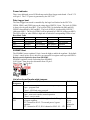
LPC315x Data Logger main board
1B
Board Power
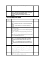
The boards have been shipped to India with jumpers configured for 5V external power
(5V power brick supplied). The DL board is also capable of being powered from an
external dc power source of 6V – 15V (requires different jumper setting at JP3 and JP4).
A 3.6V/3.7V (nominal) Li-Ion battery can be used with either the 5V or 6-15V external
power source.
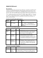
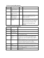
External power supply Jumper settings
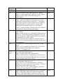
5V external power supply – JP3 pin 2 jumper to JP4 pin 2; caution do not connect to
power supply greater 5.5V in this configuration otherwise there could be damage to
components on the board, including the LPC315x. In this configuration the external 5V
is supplied directly to the board +5V, which supplies the LPC315x PSU_VBUS.
6V – 15V external power supply – JP3 pin 1 to pin 2 jumper; JP4 pin 1 to pin 2 jumper.
In this configuration the external 6-15V is supplied to a step-down power converter
which outputs to the board +5V net.
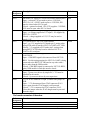
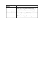
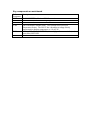
Using external power only, no Li-Ion battery
When the Data Logger is powered strictly from power mains through the external dc
power jack (J4) and no Li-Ion battery will be connected to the board, diode D6 must be
installed to get power to the GSM cellular module.
Using Li-Ion Battery power
When a Li-Ion battery will be used with the Data Logger board (P2 or P2A), ensure that
D6 is either not installed or lift D6 pin 1 off the pcb.
Battery charger software
The LPC315x battery charger software needs to be developed; India team?