1
INSTALLATION & WIRING
CHAPTER
4
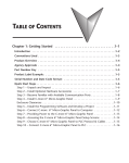
In This Chapter...
Safety Guidelines . . . . . . . . . . . . . . . . . . . . . . . . . . . . . . . . . . . . . . . . . . . . . . . . . . .4–2
Introduction . . . . . . . . . . . . . . . . . . . . . . . . . . . . . . . . . . . . . . . . . . . . . . . . . . . . . . .4–3
Panel Cutout Dimensions (all models) . . . . . . . . . . . . . . . . . . . . . . . . . . . . . . . . . . .4–4
Wiring Guidelines . . . . . . . . . . . . . . . . . . . . . . . . . . . . . . . . . . . . . . . . . . . . . . . . . . .4–5
Chapter 4: Installation and Wiring
1
2
3
4
5
6
7
8
9
10
11
12
13
14
A
B
C
D
Safety Guidelines
4–2
NOTE: Products with CE marks perform their required functions safely and adhere to relevant standards as
specified by CE directives provided they are used according to their intended purpose and that the
instructions in this manual are adhered to. The protection provided by the equipment may be impaired if this
equipment is used in a manner not specified in this manual. A listing of our international affiliates is available
on our Web site: http://www.automationdirect.com
WARNING: Providing a safe operating environment for personnel and equipment is your responsibility and
should be your primary goal during system planning and installation. Automation systems can fail and
may result in situations that can cause serious injury to personnel or damage to equipment. Do not rely
on the automation system alone to provide a safe operating environment. You should use external
electromechanical devices, such as relays or limit switches, that are independent of the PLC application
to provide protection for any part of the system that may cause personal injury or damage. Every
automation application is different, so there may be special requirements for your particular application.
Make sure you follow all national, state, and local government requirements for the proper installation
and use of your equipment.
Plan for Safety
The best way to provide a safe operating environment is to make personnel and equipment safety
part of the planning process. You should examine every aspect of the system to determine which areas
are critical to operator or machine safety. If you are not familiar with control system installation
practices, or your company does not have established installation guidelines, you should obtain
additional information from the following sources.
• NEMA — The National Electrical Manufacturers Association, located in Washington, D.C. publishes
many different documents that discuss standards for industrial control systems. You can order these
publications directly from NEMA. Some of these include:
ICS 1, General Standards for Industrial Control and Systems
ICS 3, Industrial Systems
ICS 6, Enclosures for Industrial Control Systems
• NEC — The National Electrical Code provides regulations concerning the installation and use of
various types of electrical equipment. Copies of the NEC Handbook can often be obtained from your
local electrical equipment distributor or your local library.
• Local and State Agencies — many local governments and state governments have additional
requirements above and beyond those described in the NEC Handbook. Check with your local
Electrical Inspector or Fire Marshall office for information.
®
EA1-MG6-USER-M Hardware User Manual, 1st Ed. Rev E, 07/13
Chapter 4: Installation and Wiring
Introduction
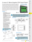
The installation and wiring of C-more 6” Micro-Graphic panels require selecting an appropriate
location for the panel, laying out the cutout dimensions on the surface of the control cabinet
that the panel will be mounted through, securing the panel with the provided mounting clips,
tightening the screws to the appropriate torque rating to assure the gasket is sealing correctly,
and finally connecting the appropriate power source to the panel.
NOTE: Each C-more 6” Micro-Graphic panel is provided with a cutout template to simplify marking the proper
cutout size on the surface of the control cabinet that the panel will be mounted through.The keypad bezels
are also provided with an appropriate cutout template for mounting convenience.
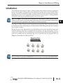
The C-more 6” Micro-Graphic panels include four mounting clips. They are fitted to the panel
by inserting two tabs into mating slots on the panel and then sliding the clip into a narrower
slot to secure it in place.
If using the panel with a Keypad Bezel, then install the panel into the keypad bezel and secure
with the mounting clips that are provided with the panel to seal the panel gasket. Create a
cutout in the enclosure that the assembled panel and keypad bezel will be mounted through and
secure the assembly with the mounting clips that are provided with the keypad bezel. See
Chapter 3: Accessories for additional details.
Mounting Clips
EA-MG-BZ2-BRK
NOTE: The C-more 6” Micro-Graphic panel (EA1-S6ML & EA1-S6MLW), 20-Button Keypad Bezel (EA-MG6BZ2) and 21-Button Keypad Bezel (EA-MG6-BZ2P) use the same type of mounting clip (EA-MG-BZ2-BRK).
®
EA1-MG6-USER-M Hardware User Manual, 1st Ed. Rev E, 07/13
1
2
3
4
5
6
7
8
9
10
11
12
13
14
A
B
C
D
4–3
Chapter 4: Installation and Wiring
1
2
3
4
5
6
7
8
9
10
11
12
13
14
A
B
C
D
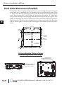
Panel Cutout Dimensions (all models)
4–4
The C-more 6” Micro-Graphic panel is mounted into a cutout through the control cabinet and
secured with four (4) mounting clips. The mounting clips are provided with the panel. There
are slots on each side of the panel’s long dimension that the two tabs on each mounting clip will
match. The mounting clips are held in place by inserting the tabs into the “T” shaped holes
(slots) and then moving the mounting clip toward the rear of the panel to keep it in place. Next
tighten the mounting clip screws to pull the rear of the panel’s bezel to the control cabinet’s
mounting surface. The screws need to be tightened to the torque rating shown in the illustration
below so that the gasket is compressed to form the proper seal between the panel and cabinet
surface.
+0.04
6.339 –0.00
0.256
[6.5]
0.260
[6.6]
+1
161.0 –0
0.256
[6.5]
R .118 [R3]
CUTOUT
OUTLINE
+0.04
4.811 –0.00
BEZEL
OUTLINE
+1
122.2 –0
CUTOUT
0.260
[6.6]
Enclosure Mounting Thickness Ranges
and Mounting Bracket Screw Torque
MOUNTING CLIP
SCREW TORQUE RANGE
21 - 28 oz-in [0.15-0.2 Nm]
ENCLOSURE MOUNTING
THICKNESS RANGE
0.04” - 0.2” [1 - 5mm]
MODEL:EA1-S6MLW
R01.1 2 3 4 5
R
INPUT:12-24V 6.5W
Date code:****
MADE IN CHINA
LISTED
7M17
IND.CONT.EQ.
EA1-S6MLW?{0752015001
®
EA1-MG6-USER-M Hardware User Manual, 1st Ed. Rev E, 07/13
Chapter 4: Installation and Wiring
Wiring Guidelines
WARNING: To minimize the risk of potential safety problems, you should follow all applicable local and
national codes that regulate the installation and operation of your equipment. These codes vary from
area to area and it is your responsibility to determine which codes should be followed, and to verify that
the equipment, installation, and operation are in compliance with the latest revision of these codes.
Equipment damage or serious injury to personnel can result from the failure to follow all applicable
codes and standards. We do not guarantee the products described in this publication are suitable for
your particular application, nor do we assume any responsibility for your product design, installation, or
operation.
If you have any questions concerning the installation or operation of this equipment, or if you need
additional information, please call us at 1-800-633-0405 or 770-844-4200.
This publication is based on information that was available at the time it was printed. At
Automationdirect.com® we constantly strive to improve our products and services, so we reserve the
right to make changes to the products and/or publications at any time without notice and without
obligation. This publication may also discuss features that may not be available in certain revisions of
the product.
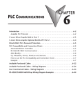
Providing Power to the C-more 6” Micro-Graphic Panel
Power can be supplied to the C-more Micro-Graphic panel in one of three different ways.
1.) The C-more 6” Micro-Graphic panel is powered during programming from the PC through the
USB to RS-232 Programming Cable Assembly, EA-MG-PGM-CBL. The panel will operate in
Low-Power mode when powered by the PC and result in a dim screen.
2.) During operation, the 6” panel functions in High-Power Mode when supplied powered by a
minimum 1 Amp 12 - 24 VDC class 2 power source. Recommended power supplies are
AutomationDirect part number PSC-24-015 or PSC-24-030.
3) During operation, the C-more 6” Micro-Graphic panel can function in Low-Power Mode powered
from most AutomationDirect PLC’s RJ12 serial communications port. Use a DV-1000CBL
communications cable, or a DV-1000CBL communications cable with a FA-15HD 15-pin HD
DSub/RJ12 Adapter connected to most AutomationDirect PLC’s 15-pin HD communications port
(DL06, D2-250-1 & D2-260) PLCs for Low-Power operation. See Chapter 6: PLC
Communications for additional details. The panel will operate in low-power mode when powered
by the PC.
NOTE: When the 6” panel is powered through Port1 from a connected PLC or PC, the screen brightness is
diminished because the panel is running in Low-Power Mode. For full brightness, connect an external
12-24 VDC class 2 power source to the panel’s power connection. Low-Power Mode is intended for initial
programming. For full brightness, connect an external 12-24 VDC class 2 power source when the panel is
installed in its application.
Wiring Guidelines continued at top of the next page.
®
EA1-MG6-USER-M Hardware User Manual, 1st Ed. Rev E, 07/13
1
2
3
4
5
6
7
8
9
10
11
12
13
14
A
B
C
D
4–5
Chapter 4: Installation and Wiring
1
2
3
4
5
6
7
8
9
10
11
12
13
14
A
B
C
D
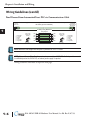
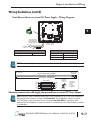
Wiring Guidelines (cont’d)
Panel Powered from AutomationDirect PLC via Communications Cable
4–6
To PLC
RJ12 Port
Power Supplied to Panel through Cable from AutomationDirect PLC RJ12 port:
RS-232C (p/n DV-1000CBL)
To C-more
Micro-Graphic
Serial Port1
10 feet [3.0 m] Maximum
Wiring Diagram
RJ12 6-pin
Phone Plug
(6P6C)
1 = Sig GND
2 = +5 VDC
3 = RXD
4 = TXD
5 = not used
6 = Sig GND
GND
6
1
GND
TXD
4
3
RXD
RXD
3
4
TXD
+5 V
2
5
+5 V
GND
1
6
GND
123456
RJ12 6-pin
Phone Plug
(6P6C)
1 = Sig GND
2 = not used
3 = RXD
4 = TXD
5 = +5 VDC
6 = Sig GND
123456
NOTE: Maximum cable length when the panel is powered via a PLC is 10 feet.
NOTE: Only one C-more Micro-Graphic panel can be powered by a CLICK PLC. If a 2nd panel is connected
to a different port on the CLICK PLC, an external power supply is required.
Wiring Guidelines continued at top of the next page.
®
EA1-MG6-USER-M Hardware User Manual, 1st Ed. Rev E, 07/13
Chapter 4: Installation and Wiring
Wiring Guidelines (cont’d)
Panel Powered from an external DC Power Supply – Wiring Diagrams
R01. 1 2 3 4 5
MODEL:EA1-S6MLW
R
INPUT:12-24V 6.5W
Date code:****
MADE IN CHINA
LISTED
7M17
IND.CONT.EQ.
EA1-S6MLW + serial number
Recommended
DC Supply Fuse
750 mA fast acting,
ADC p/n AGC-75
1
9
Supply to Panel:
1 A @ 12 - 24 VDC
(10.8 - 26.4 VDC)
GND
Equipment
Ground
8
15
–
+
Tightening Torque
Power supply wire connection
Required Wire Specification
1.7 lb-in (0.2 Nm)
Supported temperature
Wire Material
Wire Size
Over 60 °C
Copper
16 - 22 AWG
NOTE: Recommended DC power supply, AutomationDirect Part No. PSC-24-015 or PSC-24-030.
To PLC
Port Connector
Cable wiring example when power is supplied to panel from
an external DC Power Adapter
To C-more
Micro-Graphic
Serial Port 1
50 feet [15.0 m] Maximum
Wiring Diagram
GND
1
GND
RXD
3
RXD
TXD
4
TXD
GND
6
GND
RJ12 6-pin
Phone Plug
(6P6C)
1 = Sig GND
2 = do not use
3 = RXD
4 = TXD
5 = +5 VDC
6 = Sig GND
123456
Maximum communication cable length when powered from an external DC Power Adapter
NOTE: When the 6” panel is powered through Port1 from a connected PLC or PC, the screen brightness is
diminished because the panel is running in Low-Power Mode. For full brightness, connect an external
12-24 VDC power source to the panel’s power connection. Low-Power Mode is intended for initial
programming. For full brightness, connect an external 12-24 VDC power source when the panel is installed
in its application.
®
EA1-MG6-USER-M Hardware User Manual, 1st Ed. Rev E, 07/13
1
2
3
4
5
6
7
8
9
10
11
12
13
14
A
B
C
D
4–7