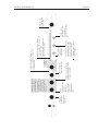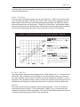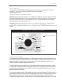
1
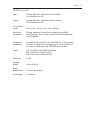
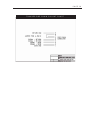
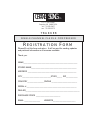
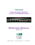
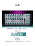
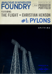
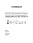
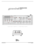
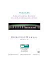
TRAKKER
SINGLE CHANNEL DISCRETE
CLASS A COMPRESSOR-LIMITER
OPERATOR'S MANUAL
Version 1.10
CRANE SONG LTD.
2117 East 5th Street
Superior, WI 54880 USA
tel: 715-398-3627
fax: 715-398-3279
www.cranesong.com
©1998, 2009 Crane Song,LTD.
Subject to change without notice.
Printed in the U.S.A.
IMPORTANT SAFETY INSTRUCTIONS
1. Read these instructions
2. Keep these instructions
3. Heed all warnings
4. Follow all instructions
5. Do not use this apparatus near water
6. Clean only with dry cloth
7. Install in accordance with the manufacturer's instructions
8. Do not install near any heat sources such as radiators, heat registers, stoves, or other
apparatus (including amplifiers) that produce heat
9. Protect the power cord from being walked on or pinched particularly at plugs and the
point where they exit from the apparatus
10. Only use attachments/accessories specified by the manufacturer
11. Unplug this apparatus during lightning storms or when unused for long periods of
time
12. Refer all servicing to qualified service personnel. Servicing is required when the
apparatus has been damaged in any way, such as power-supply cord or plug is damaged, liquid has been spilled or objects have fallen into the apparatus, the apparatus
has been exposed to rain or moisture, does not operate normally, or has been dropped
13. CAUTION: To disconnect the unit completely from the MAINS, unplug the unit. Turning the power switch off does not disconnect the unit completely from the MAINS.
TABLE OF CONTENTS
INTRODUCTION
PAGE
........................................... 2
PANEL REFERENCE
..................................... 3
CLASS A DISCRETE TOPOLOGIES ................. 4
Heating and Warm-up ............................ 4
CONTROL DESCRIPTION .............................. 4
The Link Switch
.................................. 6
The Character Switch ............................... 6
AMPLIFIER TYPES ......................................... 7
TRAKKER NOTES
Character Switch Suggestions .................. 8
SIDE CHAIN .................................................... 8
Pin Out Chart ........................................... 10
LINK CONNECTOR .......................................... 8, 11
INTERFACING ................................................ 9
REGISTRATION FORM ..................................... 12
PAGE 2
INTRODUCTION
TRAKKER is a high quality Single Channel Discrete Class A Compressor-Limiter. It functions
either as a musically transparent compressor or as a vintage compressor-limiter with selectable
hard or soft knee. TRAKKER can create distinct new sounds or maximize existing ones. An
additional feature of the TRAKKER is the ability to link up to 8 units for surround mixing.
The TRAKKER has adjustable threshold, attack, release, knee shape, and makeup gain controls.
In addition to these controls, a function switch allows the selection of transparent operation or
vintage operations such as optical, air optical, soft knee, and hard knee – each with four different
amplifier/gain control sounds.
The amplifier/gain control sounds are:
• Transparent
• Vintage (tube or old style class A)
• Transparent with VCA artifacts and
• Vintage with VCA artifacts.
The front panel contains a 22 element VU meter with over load indicator to show gain reduction
and allow accurate monitoring of output levels. In the link mode the master unit controls all
functions of the slave units except for make-up gain.
TRAKKER has transformer-less balanced inputs and outputs. The unit is 1 rack space tall and
operates from 100V, 115V, 230V or 240V mains.
TRAKKER is a maximum-versatility toolkit for solving real-world recording, broadcast, and sound
reinforcement problems with the utmost attention to signal quality. From single channel operation
to bus compression, TRAKKER can provide an artistic choice of sounds at the flip of a switch.
THRESHOLD Determines the
amount of gain
reduction
ATTACK Determines the time
it takes the
compressor to
respond to input
signal for gain
reduction to take
place.
KNEE - Changes the
shape of the gain curve.
* soft knee
settings
METER SWITCH - selects the
type of display for the meter.
The red CLIP indicator lights
when the unit is clipping in
the output stage on either of
the two settings.
LINK - allows up
to 8 units to be
linked together
GAIN - adjusts
compressor gain
from 0 - 14dB.
BYPASS - selects
output signal source.
*Unit defaults to
hardwired bypass when
off.
METER - has 2 modes of operation
1) as a bar graph in the "out" mode; 0VU
referenced to +4dBm
2) a dot type display that shows gain
reduction, in the "gr" mode.
CHARACTER SWITCH - allows the
selection of different sound types from
vintage to modern.
RELEASE - Sets the time for gain
to return to the point of no gain in
the absence of program.
Attack and Releast times
interact with amount of
gain change, setting of
the character switch,
and program material to
allow the creation of a
wide variety of sounds
unique to Crane Song
Compressors.
PANEL REFERENCE
PAGE 3
PAGE 4
CLASS A DISCRETE TOPOLOGIES
The TRAKKER has a Class A audio path which is significantly different than designs that use
integrated circuits. Class A circuits sound musically pleasing because their distortion components tend to be Second Harmonic. IC Op-Amps do not have class A output circuits and their
distortion components tend to be high order odd harmonics; not musical. The two important
things to remember are that Class A circuits sound musically pleasing and discrete circuits can
be tailored for optimum performance.
Class A discrete technology has 2 disadvantages when compared to IC designs. 1) Due to the
large number of parts in discrete circuits; they are costly. 2) Class A circuits run hot.
HEATING AND WARM-UP
The TRAKKER must have adequate ventilation. Make sure the vent holes are not blocked.
Do not set anything directly on top of the TRAKKER. When mounting the unit in a rack, provide
as much air flow as possible. A 220 volt muffin fan run on 115 volts makes a quiet fan and can
provide good cooling for the rack if needed. Leaving the back of the rack open is another option.
Providing adequate ventilation, will reward you with years of reliable operation.
All precision electronic equipment has an operating temperature that when reached will result in
best performance. The TRAKKER should be allowed a 10 to 15 minute warm up period before
use.
CONTROL DESCRIPTION
THRESHOLD
The threshold control governs the amount of gain reduction. The amount of compression is
increased as the control is turned clock wise. The compressor can be operated with "soft-knee"
or "hard-knee" compression curves. When changing between the soft and hard knee, readjustment of the threshold control is necessary because the side chain operates differently. Operation in "hard-knee" may require a higher threshold setting than operation in "soft-knee".
GAIN CONTROL
The gain control will adjust the compressor gain from 0 to 14 dB of gain. When in link mode the
gain control operates independently to allow balancing of the program source. (See "link switch"
description.)
ATTACK CONTROL
The attack control determines the time it takes the compressor to respond to the input signal and
have gain reduction take place. Zero on the control is fast; 10 is slow.
RELEASE CONTROL
The release control sets the time for the compressor’s gain to return to the point of no gain
reduction in the absence of program. Zero on the control is fast; 10 is slow.
The attack and release times depend on the knee control setting, the amount of gain change, the
setting of the character switch, and the program material. They all interact and allow the creation
PAGE 5
of a wide variety of sounds possible only because of a proprietary gain control device used in
Crane Song compressors.
KNEE CONTROL
The knee control changes the shape of the knee or gain curve. With the control set to 0 the
curve and slope are gentle. With the control set to 10 the curve is more aggressive and the
slope is higher. Be aware that as the knee setting becomes higher the attack and release
times are modified, they are made faster. The gain curve is the input - output signal relationship from which the ratio can be determined. By looking at the knee graph below it is evident
that the ratio changes depending upon where on the gain curve the unit is operated.
KNEE
& INPUT/OUTPUT GAIN RELATIONSHIP GRAPH
Graphs A,B, & C show hard knee settings;
A & B with the knee control set to 10, C with
the control set to 0.
A
B
C
D
E
F
Graph A shows 10dB of Gain reduction
with an input of +25 dBm. Graphs B & C
show 15 dB of Gain Reduction with the input
at +25dBm.
Graphs D,E, & F are in the non-hard knee
settings. Graph E shows 15 dB of gain
reduction when the input is +25dBm with
the knee control set to 0. Graphs D & F
show 15 or 20dB of gain reduction with the
maximum input and the knee control set to
10.
BYPASS SWITCH
The bypass switch selects the output signal source. When switched to "in" – the unit is in the
audio path. When switched to the "out" position, all of the compressor circuitry is removed
from the audio path. When in the "out" position, the unit is hardwired to the output, i.e. hard
bypassed. The compressor-limiter, however, continues to operate in a monitoring mode. The
unit defaults to the bypass (out) state when the power is turned off or when the power fails.
METER
The meter has two modes of operation; output and gain reduction. In the "out" mode the
meter appears as a bar graph. 0 VU is referenced to +4dBm. The "gr" mode shows gain
reduction and appears as a dot type display. The red CLIP LED indicator lights when the unit
is clipping in the output stage on either of the two settings.
PAGE 6
LINK
SWITCH
A unique feature of TRAKKER is the ability to use one unit as a master/controller with up to 7
slave units. The rules for operating TRAKKER in link are as follows:
1) Only one master unit
2) If any unit is turned off the link goes away.
Allowing Link Turning the link switch "on" will light the red indicator next to the switch when link
is allowed. Switching the link "on" turns that unit into the master/controller unit. The master unit
now controls all functions of all units except gain control. The gain controls operate independently regardless of the link being on or off.
Disallowing Link The link system allows only one master/controller device. The link will be
disallowed if; 1) multiple link switches are on, or 2)power to any TRAKKER in the link is turned off
or fails.
CHARACTER
Vintage-VCA
Clean-VCA
Vintage
Clean
SWITCH SETTINGS
denotes soft knee settings
Vintage
Clean- VCA
Vintage-VCA
Vintage-VCA
Clean-VCA
Vintage
Clean
Clean-VCA
Vintage-VCA
CHARACTER SWITCH
The character switch allows the selection of 16 different sound types; in essence giving the user
the ability to combine the different sections of the amplifiers. The four basic compressor - limiter
types are: optical, air-optical, soft knee and hard knee. Each of these basic types has four
different amplifier/modulation styles to choose from.
The optical setting has a sound like many of the classic optical compressors and their modern
counter parts. The optical settings are program dependent. This means that the more time that
signal is present the longer the release time becomes. Increasing the release time on the compressor will increase the effect.
The Air-optical setting is similar to the optical setting, but with one difference. This difference is a
high frequency effect also found in certain vintage tube compressors. The high frequency effect
is the result of a circuit that was used to achieve flat frequency response in the old gear. In
TRAKKER this high frequency compensation is used to the advantage of the sound. The result
PAGE 7
is an airy high end to the sound.
The Soft knee settings provide a classic soft characteristic similar to many tube and solid state
feedback type compressors. The soft knee setting does not have a program dependent release
time. The release time is determined by the release control only.
The hard knee can be thought of as a limiter although TRAKKER has adjustable attack and
release times. The knee control changes the ratio when operating in the hard knee mode. Hard
knee means the knee has a hard break point. When the signal is above this break point, compressor / limiter action takes place. Below this point no gain control action takes place. This is
typical of many classic units that fit the hard knee category.
NOTE*** The threshold control will need re-setting when changing between hard knee and any
other character knob settings (i.e. optical, air-optical, soft knee) because the side chain becomes
completely rearranged when switching between the hard and any other knee settings.
AMPLIFIER TYPES:
CLEAN, VINTAGE, CLEAN-VCA, VINTAGE-VCA
The clean setting is a very transparent discrete class A audio path. This is the most transparent
audio path in the device. The clean setting imparts the least amount of color on the sound.
The vintage audio path has color similar to a triode tube circuit and single ended Class A transistor circuits. The color is mostly second harmonic with third harmonic being introduced when
clipping is approached. Using this setting will result in a rich, fat, warm sound.
Many vintage tube and solid state compressors have small amounts of control voltage feed
through and other modulation artifacts that take place with gain changes. The VCA settings add
these types of modulation artifacts to the audio path. It is important to note that the color added
by the VCA setting is dynamic. This means that the sound change is only heard when
TRAKKER’s gain is changing and is more prevalent with fast attack and release settings. The
sound setting is called VCA on the front panel. (The VCA artifact can be attached to the clean or
vintage sound.)
Combining the two amplifier sounds and the VCA sounds results in 4 different audio paths to
chose from. When the 4 different compressor characteristics are included, there are 16 different
sounds to choose from. This does not include the large variation in sound that is possible with the
different attack, release, and shape settings.
Because of relay switching, when changing the character switch there will be a small clicking
noise. The signal turns off for .2 ms thus causing the click. It will only happen when there is
signal present. If it was possible to change the relay at zero crossing of the signal, there would be
no click. By using relays the audio path quality is maintained.
PAGE 8
TRAKKER NOTES:
CHARACTER
SWITCH SETTING SUGGESTIONS
A good starting place is optical clean, attack set at 4, release set at 5.5, and knee set at 6.
Sound with these settings will be similar to the classic LA-3. When the character switch is set
to optical vintage, attack set at 4, release set at 5.5, and knee set at 6; the sound is similar to
the classic LA-2A. Varying the release and shape knobs will change the sound from more up
front to softer. The softness is the main sound difference between the modern versions of the
optical compressor and the original.
If a hard edged sound is desired, use the hard knee settings.
* Watch our website, www.cranesong.com ,for additions/changes to this section.
SIDE CHAIN
The side chain connector is a DB 9 connector. The inputs and outputs are balanced. Keep in
mind that this is an insert point and must be normaled when not being used. If a connector is
not installed in the back of the unit, the side chain insert can be ignored because it is disabled.
The side chain is for inserting an equalizer into the control path. Due to the design of the link
system, separate equalizers (with identical settings) must be used for all channels to achieve
channel matched operation when in the link mode. This scheme allows reliable signal averaging regardless of the phase relationship between the audio channels. The approach used in
TRAKKER is beneficial for stereo FM broadcast where phase relationships can affect the
stereo generator. In a conventional link circuit (one which uses a single EQ for all channels)
out of phase material is ignored by the compressor.
Many different sounds can be created by using an equalizer in the side chain. TRAKKER can
respond to a frequency that is causing a problem. In the hard knee mode, if all lows are cut and
the hi frequency content is boosted, TRAKKER can function as a de’sser. If every thing below
80 Hz is cut, TRAKKER will not respond to the low frequency content of a signal. By modifying
the side chain frequency response, infinite variations can be created.
LINK CONNECTOR
The link connector is a 15 pin DB style connector. There are control voltages and logic signals
in the link cable. Because of this the AC power cable should be kept away from it. It is also
good practice to keep audio cables separated from the power cable. The order that the connectors are plugged in does not matter. When using a cable with extra positions the one with
the loop must be plugged in for the system to link.
PAGE 9
INTERFACING
Input:
Floating, balanced. Maximum input is +25 dBm.
The connectors are XLR.
Output:
Floating, balanced. Maximum output is +25 dBm.
The connectors are XLR.
For Input and
Output :
Pin 2 is Sig + , Pin 3 is Sig – , Pin 1 is GND
Side Chain
Connections:
Floating, balanced. Connections are made by using a DB-9
Male Connector. This is a loop insert and must be normaled back
to the TRAKKER.
Unbalanced
Connections:
Are made by tieing the SIG – Pin to the GND Pin. If the connection
is an input, it is best to tie at the signal source. If the connection is
an output, it is best to tie at the TRAKKER XLR connector.
Power:
100, 120, 230,240 volt; 50/60 Hz; 45 watts
MDL 0.4A Fuse for 100V and 120V
MDL 0.25A Fuse for 230V and 240V
Pilot Lamp:
# 7335
Shipping
Weight:
14 lbs. (6.34 kg)
Depth
Behind Panel:
10 inches plus cabling
Panel Height:
1 rack space
PAGE 10
TRAKKER SIDE CHAIN PIN OUT CHART
PAGE 11
CRANE SONG
LTD.
2117 E. 5th Street
Superior, WI 54880 USA
tel. 715-398-3627
fax. 715-398-3279
TRAKKER
SINGLE CHANNEL CLASS A COMPRESSOR
REGISTRATION FORM
Please fill out this form and return. It will be used for sending updates
and pertinent information as it becomes available.
Thank you.
NAME___________________________________________________
STUDIO NAME___________________________________________
ADDRESS ______________________________________________
CITY___________________________STATE_____ ZIP___________
COUNTRY________________PHONE ________________________
SERIAL # _______________________________________________
DEALER___________________________________________________
PURCHASE PRICE _______________________
EMAIL _______________
WEBSITE_____________________