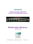
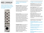
1
Pittsburgh Modular Foundation 2.0 Synthesizer Manual and Patch Guide 2 Important Instructions – PLEASE READ Read Instructions: Please read the Foundation Synthesizer manual completely before use and retain for future reference. IMPORTANT Ribbon Cable Power Information: The Foundation combines a set of individual modules to create a complete synthesizer. The individual modules can be rearranged, removed, and replaced with other Foundation and Eurorack compatible modules from Pittsburgh Modular or other manufacturers. The Foundation uses standard Eurorack ribbon power cables to connect the modules to the internal bipolar +/-‐12v DC power supply. Please pay very close attention to the orientation of the ribbon cable when adding and removing modules. The stripe on the ribbon cable marks -‐12v. This stripe needs to line up with the -‐12v pins on the power supply and the -‐12v pins on the module. Failure to match up the pins correctly can result in damage to one or all the modules in the Foundation. On the power board, the -‐12v pins are clearly labeled. On the individual modules, the positive and negative sides of the pin connectors are labeled next to the power header on either the top or bottom of the PCB. Do NOT remove individual modules from the Foundation while Foundation is plugged in. Do NOT unplug ribbon cables from the Foundation or individual modules while the Foundation is plugged in. 3 Table of Contents Important Instructions ……………...…….......................…… 3 Table of Contents …………………………….......................…... 4 Case and Power SpeciOications ……….......................…..… 5 Foundation Package Contents……...…........................…… 5 An Introduction to Modular Synthesis ..…...................... 6 Audio Signal Path …………..……........................................….. 7 Control Voltage Signal Path …....................…...................... 7 Individual Modules ……………….…….....................….... 8-‐19 Patching a Modular Synthesizer ……......................……. 20 Patch Guides ……………….....................….. 21 -‐ 40 1 Year Limited Warranty…………….....................…...…... 41 Service and Other Information ………......................…... 42 4 SpeciOications and Foundation Package Contents Foundation Package Contents: 1 -‐ Foundation Modular Synthesizer 1 – Pittsburgh Modular Patch Cable Kit 1 – Manual and Patch Guide 1 – External Power Adapter Case and Power Supply: External Dimensions: Heavy Duty Road Case with Removable Lid: 19.25” x 6.25” x 6” Custom Hardwood Desktop Case: 19.25” x 4.5” x 6.5” Internal SpeciOications: 90hp Eurorack Case Sliding Nut Mounting System External Power Adapter: Connection: 2.1mm Barrel Type Output: 15V-‐18V DC / 1A 5 An Introduction to Modular Synthesis The Foundation was designed to be a complete, fully modular analog synthesizer. A modern version of the great 1970's monosynths conveniently broken down into individual components with no hardwired signal Olow to restrict experimentation. Oscillators, mixer, Oilter, ring modulator, ADSR, etc. are all individual modules. Because each module performs a single function, without patch cables the Foundation will not produce sound. A synthesizer voice must Oirst be patched up using cables to wire modules together. The Foundation allows the signal Olow to be rewired with every patch. The voice can be as simple as listening to the triangle output of an oscillator or as complex as a self running patch using all the modules. 6 Audio Signal Path and Control Voltage Signal Path The Foundation signal path is divided into two types of signals. Audio signals and control voltages. The audio signal is represented by the sound that is produced. The audio signal path starts at a sound source such as an Oscillator, LFO running at audio rate, or the Filter in oscillator mode. The audio signal is then patched through other modules used to shape the sound such as mixers, Oilters, and ampliOiers. Control voltages (CV) are used to manipulate the audio signal in several different ways. Gates are represented by a high or low control voltage. A gate can be generated using a square or pulse wave from an oscillator or LFO, or by using the GATE output on Midi module. A gate can be shaped using an envelope generator to control the attack, decay, sustain, and release of the gate. The modiOied gate signal can then be sent to any CV input on the Foundation. A second use for control voltages is as a modulation source. For example, a control voltage from the CV output of the Midi module patched into the 1V input on the Oscillator controls the frequency of the Oscillator based on the Midi note received. The LFO2 module provides two separate low frequency oscillators that make perfect control voltage modulation sources. Audio signals also make a great control voltage source for Oscillator FM (frequency modulation). As always, experimentation is essential to getting the most out of the Foundation. 7 Individual Modules The Foundation is a collection of 13 modules chosen to allow the creation of complex analog sounds. The modular nature of the Foundation allows for deep experimentation and a virtually unlimited sound palate with no hardwired signal path or Oixed voice architecture to restrict creativity. The following pages describe the functionality and controls of each module. 8 Midi2 Module Description: The Midi2 converts standard midi note messages into the analog control voltages used by modular synthesizers. This allows a modular synthesizer to be controlled by a midi keyboard, sequencer, or DAW. The Midi2 module has 3 distinct modes of operation. 1. Monophonic -‐ Gate2 and CV2 outputs mirror the outputs of Gate1 and CV1. Monophonic mode works great when using a modular as a single voice synthesizer. 2. Duophonic -‐ The Midi2 module uses the two sets of Gate and CV outputs to allow two notes to be played simultaneously. The Oirst midi note is sent to the Gate1 and CV1 outputs and the second is sent to the Gate2 and CV2 outputs. Duophonic mode is perfect when working with a two voice modular synthesizer. 3. Dual Monophonic -‐ Gate 2 and CV2 outputs are controlled by a different midi channel than the Gate 1 and CV 1 Outputs. Dual Monophonc mode allows a modular to be controlled by two separate sets of midi data. This mode works well when using a modular as two single voice synthesizers Controls: GT1 Output – Note on = Gate high (+5v), Note off = gate low (0v) CV1 Output – 1 volt per octave voltage derived from note played on keyboard. GT2 Output – Note on = Gate high (+5v), Note off = gate low (0v) CV2 Output – 1 volt per octave voltage derived from note played on keyboard. Sync Output – Press to assign midi note channel or midi CC channel. Midi Input – Input jack for a standard 5-‐pin midi cable. 9 Oscillator Module(x2) Description: A wide range, multiple waveform generator. The Oscillator has a frequency range starting as low as 7 seconds per cycle, allowing it to double as a voltage controlled LFO. Controls: Big Knob – Course frequency setting. Fine Knob -‐ Fine tune frequency setting. This control is calibrated to a range of 1 octave. 1V Input -‐ CV input used to track the Oscillator at 1 volt per octave. RT -‐ CV Input used to hard reset the Oscillator on the falling edge of the incoming waveform. FM Knob and Input -‐ Linear frequency modulation CV input attenuator and input. PW Input -‐ Pulse width modulation CV input. Affects the pulse width of the square wave PW Knob -‐ Manually controls the pulse width of the square wave. SIN Output – Sine wave output TRI Output – Triangle wave output SAW Output – Saw wave output SQR Output – Square wave output 10 M3 Module Description: The M3 is a unique signal routing module with 3 distinct sections able to perform several different functions at once. Signal splitting, mixing, and buffering are combined to create a module that is both compact and incredibly useful. The top section labeled MULT, is a standard 4 jack passive multiple used to create 3 copies of the original signal. One input becomes up to 3 identical outputs. The bottom 2 sections, MIX1 and MIX2, both function the same way. Two input and 2 outputs allow each section to be used as a 2 channel unity gain mixer, signal buffer, and buffered multiple. Controls: Section 1 (MULT) All 4 jacks function the same. Although the jacks are labeled I, O, O, O, any jack can be used as the input allowing the remaining 3 jacks to be used as outputs. Section 2 and 3 (MIX1 and MIX2) There are two types of jacks in the Mix sections, inputs (I) and outputs (O). Each Input functions identically and each output functions identically. The two inputs can be used together to create a 2 channel unity gain mixer and the two outputs can be used as a buffered multiple. Combining both features together allows the M3 to perform a wide range of functions at once. 11 LFO2 Module Description: A dual low frequency oscillator module. It uses two different types of low frequency oscillator circuits to provide a variety of CV and audio rate modulation options. The top LFO utilizes rate and symmetry controls to generate shifting waveforms. Adjusting the symmetry control varies the shape of the TRI output waveform from a saw tooth to triangle to ramp wave. The symmetry control also adjusts the pulse width of the SQR wave output. The bottom LFO is a simple triangle based low frequency oscillator with rate control over the triangle and square outputs. LFO 1 Controls (top) Rate Knob -‐ Coarse frequency setting. Symmetry Knob -‐ Modify the shape of the waveforms. TRI Output -‐ Saw / Triangle / Ramp wave output Range Switch -‐ Switches the frequency range. SQR Output -‐ Square / Pulse wave Output LFO 2 Controls (bottom) Rate Knob -‐ Coarse frequency setting. TRI Output -‐ Triangle wave output Range Switch -‐ Switches the frequency range of LFO 2. SQR Output -‐ Square wave output 12 Modulator Module Description: The Modulator offers 3 types of effects based on the standard Ring Modulator circuit. Typical uses can create bell-‐like or metallic sounds. Type 1: Ring Modulator -‐ Outputs the sum and difference of the X and Y inputs. Type 2: Floating Z Modulator -‐ Outputs the sum and difference of the X and Y inputs summed with the ambient voltage within the circuit. Type 3: Linear Amplitude Modulator -‐ Outputs the sum and difference of the X and Y inputs summed with the carrier (Y) signal. Controls: X Signal Attenuator and Input Y Signal Attenuator and Input X Mix Output Attenuator used to mix the X input with the output of the modulation circuit Ring Modulator Type Switch OUT -‐ Ring modulator output LFO 1 Controls (top) Rate Knob -‐ Coarse frequency setting. Symmetry Knob -‐ Modify the shape of the waveforms. ! 13 Mixer Module Description: A Olexible, low-‐noise four channel mixer and/or attenuator for audio and CV that can be used in several ways. Three of the four channels have an output that removes the channel from the mixer circuit and allows it to become a standalone attenuator. The pots are wired with a logarithmic volume curve that is tuned for use with audio but it will work with CV as well. Patching the output of channel 1, 2, or 3 will remove it from the mixer circuit. Channel 4 can not be removed from the mixer circuit, however if channel 1, 2, and 3 are all being used as attenuators, channel 4 is the only input remaining in the mixer allowing it to be used as a buffered attenuator. The Mixer can be used as a… 4 Channel Mixer 4 Independent Attenuators 2 Attenuators and a 2 Channel Mixer 1 Attenuator and a 3 Channel Mixer 14 Filter Module Description: The Filter is a voltage controlled, analog, state variable Oilter. The state variable topology was chosen because it allowed us to produce a very smooth and natural sounding Oilter, in addition to offering several other modes of operation, each with a unique sound and energy all their own. The Filter deOines the sound of Pittsburgh Modular. It offers a warm, organic sweep through the full frequency range. The lowpass Oilter is gummy and relaxed while the highpass is clean and deOined. The goal was to produce a Oilter that did not have a sweet spot; where the every turn of the frequency knob produced something interesting. Modes of Sound Multiple Oilter responses are available simultaneously including lowpass, highpass, and bandpass. The fourth Oilter response is a variable response that shifts between lowpass, notch, and highpass. Switch It Up Two switches, Gain and Mode, further expand the capabilities of the Filter. The Gain switch modiOies the functionality of the Q while the Mode switch toggles between Oilter and oscillator modes. Setting the Gain switch to "1" converts the Q setting into a VCA circuit for the audio input. Switching the Gain switch to "Q" returns the standard Oilter Q response. 15 Filter Module (continued) Mode switches between Filter and Oscillator modes. Set to "Filter", the Pittsburgh Modular Filter will not self oscillate. Set to "Oscillator" the Filter produces a high quality voltage controlled sine wave. Adjusting the Q while in Oscillator mode modiOies the shape of the waveform. At more extreme settings the Q adds anything from warm fuzz to heavy distortion the incoming audio. Controls: Q Pot: Adjusts the resonance (Q) of the Oilter. FREQ Pot -‐ Adjusts the Frequency of the Oilter. L-‐H Pot -‐ Sweeps between lowpass, notch, and highpass Oilters. QCV Pot and Jack -‐ Resonance (Q) control voltage input and attenuverter. FCV Pot and Jack -‐ Frequency control voltage input and attenuverter. 1-‐Q Switch -‐ Switch between Gain to 1 (VCA Mode) and Gain of Q (Standard Mode) F-‐O Switch -‐ Switch between Filter and Oscillator Modes LOW Jack -‐ Lowpass Output L-‐H Jack -‐ Output based off of the L-‐H Pot HI Jack -‐ Highpass Output BND Jack – Bandpass Output 16 ADSR Module (x2) Description: The ADSR is a four stage envelope generator with independently adjustable Attack, Decay, Sustain, and Release stages. An envelope generator is used to shape control voltages such as the gate of the Midi module or a square wave from the LFO2. Controls: A Pot -‐ Attack Stage Control D Pot -‐ Decay Stage Control S Pot -‐ Sustain Stage Control R Pot -‐ Release Stage Control I Jack -‐ Input Jack Range Switch -‐ Adjust the range of the stage controls between short and long. O Jack -‐ Output Jack 17 Dual VCA Module Description: The Dual Index is a dual linear voltage controlled amplifier (VCA) and a two channel voltage controlled mixer. It has two standalone VCAs and a fully buffered mix output. Each channel offers offset gain and CV attenuation. The CV and IN of channel 2 are normaled to channel 1. If left un-patched, channel 2 will operate using the channel 1 CV and IN signals. Controls: Index 1 (VCA 1): CV -‐ CV Input used to control the VCA. CV Knob -‐ CV input attenuator. In -‐ Signal Input Out -‐ Signal Output Index 2 (VCA 2): CV -‐ CV Input used to control the VCA. CV Knob -‐ CV input attenuator. In -‐ Signal Input Out -‐ Signal Output Mix -‐ Fully Buffered mix of the VCA 1 and VCA 2 outputs. 18 Outs Module Description: A simple way to get sound out of the Foundation. Outs is a dual independent output module featuring a stereo 1/4" headphone ampliOier output and dual mono 1/4" line level outputs. Left and Right inputs are available. If only the left input is used, it is sent to both the Left and Right outputs. 19 Patching a Modular Synthesizer The following pages contain many examples of how to patch the Foundation. The examples have been chosen to showcase the Olexibility of the Foundation and to highlight as many features from each module as possible. Use the patches provided as a teaching tool. Once you have setup a patch, adjust knobs and remove cables from the Foundation while referencing the module description pages within the manual. This will help develop an understanding of what function each part of the patch is performing. The patch guide provides at least one "_______ Module Highlight" Patch for each module within the Foundation. These patches are designed to showcase the core functionality as well as additional features of the highlighted module. In general, the Highlight patches will provide a way to focus attention on the capabilities of a single module and may not provide results that would be considered musical. Working with individual modules can be fun but the true power of any modular synthesizer comes when different modules start to interact. Patching the output of one module to the input of another is a fundamental part of modular synthesis. Even though the Foundation is designed to be a tabletop modular, the patches can become complex quickly. Any output on the Foundation can be patched to any input. Understanding the capabilities and functionality available from each module will allow even the most complex patches to be understood easily. If you come up with a good patch, we want to try it! Send all your interesting patches to [email protected]. 20 21 22 23 24 25 26 27 28 29 30 31 32 33 34 35 36 37 38 39 40 Warranty 1 Year Limited Warranty: For a period of one year after the date of original purchase, the instrument and all factory installed parts and modules manufactured by Pittsburgh Modular Synthesizers LLC. are warranted to function properly and be free of defects in materials and workmanship. Should a factory installed module fail during the warranty period, contact Pittsburgh Modular Synthesizers. LLC. We will repair it (or at our option, replace it) at no charge, and pay the cost of shipping it back to you. The case and all case related hardware are warranted to function properly and be free of defects in materials and workmanship for 1 year. Patch Cables are not covered by the 1 Year Limited Warranty. This warranty is void if in our opinion the instrument has been damaged by accident, mishandled, altered, improperly serviced, or repaired by the customer where such treatment has affected its performance or reliability. This includes but is not limited to damage related to incorrectly attaching power ribbon cables. In the event of such misuse/abuse by the customer, costs for repairs plus two-‐way shipping costs will be borne by the customer. Instruments found defective should be returned to the factory carefully packed, as the customer will be responsible for freight damage. Incidental or consequential damages or costs incurred as a result of product malfunction are not the responsibility of Pittsburgh Modular Synthesizers LLC. 41 Service and Information Please contact us for service or other information. [email protected] www.pittsburghmodular.com/contact/ 42 43 Copyright 2012 Pittsburgh Modular Synthesizers LLC. 44