1
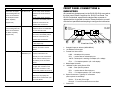
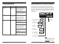
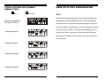
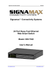
USER’S MANUAL Ethernet 10/100 Transceiver Series DL221/DL221A June 1999 ETHERNET 10/100 TRANSCEIVER INSTRUCTION MANUAL SERIES DL221/DL221A INTRODUCTION Thank you for purchasing the Radiant Communications Series DL221/DL221A fiber optic transceiver. We hope that this manual will help you quickly and easily install your transceiver. If you still need help installing or troubleshooting your transceiver after reading this guide, please call our tech support department at 1-800-969-3427. This manual details the installation procedures, specifications, and trouble shooting guidelines for the Radiant Communications Series DL221/DL221A family of fiber optic transceivers. CONTENTS OF SHIPPING CONTAINER The shipping container should contain the following items: · One (1) Series DL221/DL221A transceiver · One (1) Power Cord · One (1) CAT5 straight cable WARRANTY Radiant Communications Corporation warrants that at the time of shipment, the products manufactured by Radiant Communications will be free from defects in material and workmanship, and will conform to the specifications furnished and approved by Radiant Communications Corporation. Should any defects appear within one year from date of shipment, Radiant Communications Corporation shall, at its sole discretion, repair or replace the defective unit. Defected units shall not be accepted for return or repair without prior authorization from Radiant Communications. Return shipments to Radiant Communications Corporation shall be at the buyers expense. Radiant Communications will return repaired or replacement equipment prepaid via best way. This warranty excludes all other expressed or implied warranties of merchantability, fitness, or otherwise. Items manufactured by suppliers other than Radiant Communications Corporation used with the equipment covered by this document are not eligible under the terms of this warranty. Radiant Communications assumes no responsibility for the performance or reliability of third-party products. Radiant Communications Corporation will not be liable for any special or consequential damages, nor for loss, damages, or expenses directly or indirectly arising from the improper use of the products, either as standalone devices or used in conjunction with other equipment and material. This warranty does not extend to any products manufactured by Radiant Communications which have been subjected to misuse, neglect, accident, improper installation, an act of God, or in violation of the instructions furnished by Radiant Communications. · This manual -2- SPECIFICATIONS GENERAL DESCRIPTION Standard Compliance: IEEE802.3u, 100BaseTx, 100BaseFx, 10BaseT 100BaseTx Port RJ-45 connector Half/full duplex support via auto-negotiation or manual 100m over UTP/STP 100 ohm cat.5 cable Auto-polarity correction MDI-II/MDI-X selection 10BaseT (switch selected) The Radiant Communications Series DL221/DL221A transceivers 100BaseFx Port 1300nm SC connectors. Optional Single Fiber (DL221A) Distance: > 100 km (DL221/SMSP) Full/half duplex switch selected Diagnostics Per Channel Full duplex, Link, Activity - 100BaseFx side Per System Power (dual, if redundant PS present) Controls Fiber side: FDX/HDX Copper side: 10/100 Mbps, FDX/HDX, Autosensing disable/ enable Environmental/Physical Power supply: Power consumption: Operating temperature: Storage temperature: Humidity: are used to connect two active ethernet network components together over a fiber optic cable. Radiants unique technology allows the same transceiver to be used for connecting 10BaseT or 100BaseT components together. The Radiant Communications Series DL221/DL221A transceivers allow for extended fiber transmission distances -- in many cases greater than 100 KM. In addition, the Series DL221A transceivers allow for bi-directional, full duplex transmission between ethernet components over a single optical fiber. It is convenient to think of the Series DL221/DL221A transceivers as having two sections -- an electrical section, which interfaces to the ethernet component; and an optical section, which interfaces to the fiber optic cable. 100/240 VAC.50/60 Hz 5 W max. 0-45OC (32-113OF) -30O-65)C (22O - 149OF) 10-90% non-condensing NOTE: Specifications subject to change without prior notice. -3- The electrical section is capable of interfacing with any 10BaseT or 100BaseT RJ-45 twisted pair port. If the ethernet port supports Problem Indication Improper network traffic Runt and late collision Corrective Action On the setup mode switches, move S6 to the DOWN position, auto negotiation, the DL221/A can be set to auto negotiate for and move it back to the UP position after one second. optimum performance. If the ethernet port does not support auto Check the channel configuration negotiation, or if a fixed data rate and/or fixed half or full duplex on the mode setup switches. configuration is desired, the Series DL221/DL221A transceivers Check that both ends of the fiber can be forced into 10BaseT or 100BaseT mode, and forced into mode (Half Duplex or Full optic link are set to the same half or full duplex mode. In addition, a crossover switch is pro- Duplex) vided, which allows the Series DL221/DL221A transceivers to connection are in the same mode Check that both sides of the UTP (10 Mbps Half duplex or 10 Mbps directly connect to either a standard or a crossover ethernet port. full duplex or 100 Mbps Half Duplex or 100 Mbps full duplex). The optical section is a 100BaseFX connection at all times. The DL221 family of transceivers supports bi-directional transmission over two single mode fibers. The DL221A family of transceivers supports bi-directional transmission over a single mode fiber. In both cases, Radiants technology allows for extended transmission distances beyond the ethernet standard. If the problem persists after carrying out the procedure, do the following: exchange two different channels with one another (both copper and fiber connections), and re-perform the requested setup. If the problem still persists, there is probably some sort of general network failure. Contact the Radiant Communications technical support department for assistance. Tel: (908) 757-7444 or (800) 969-3427 Fax: (908) 757-8666 E-mail: [email protected] -4- - 13 - Problem Indication Corrective Action The DL221 full duplex FDX LED not lit On the setup mode switches, is not working when the check that S1 is UP and S3 is DL221 is connected to DOWN. the full duplex without On the setup mode switches, NWAY capability move S6 to the DOWN position, (copper side) and move it back to the UP FRONT PANEL CONNECTIONS & INDICATORS All connections (except power) to the DL221/DL221A are made at the front panel. Below is a picture of a DL221 Front Panel. The DL221A is identical, except that the duplex fiber connector is replaced with a single fiber connector. Please familiarize yourself with the front panel before attempting to configure the transceiver. position after one second. The DL221 half duplex FDX LED lit On the setup mode switches, is not working when the check that the S1 is DOWN OR DL221 is connected to S1 is UP and S3 is UP. the NWAY capability On the mode setup switches, (copper side). move S6 to the DOWN position, and move it back to the UP position after one second. Check that the connected device is half duplex only. Check the interconnection between the DL221 and the device. Fiber link not working Link LED Check that the receive fiber is (100BaseFx) not properly connected to the lit transmit port of the remote fiber device and the transmit port to the receive port of the remote device. Check that the fiber optic power is higher than -30 dbm on the receive fiber connector at the DL221 end (-26dBm for DL221A) Check the remote devices receive port is properly connected to the transmit fiber optic port of the DL221. - 12 - 1 2 3 4 5 6 Front Panel View 1. Straight/Crossover selector (MDI-II/MDI-X) 2. 10/100BaseTX Connector 3. Twisted Pair Status LEDs LINK twisted pair link present RCV receive data on twisted pair port 100TX Twisted pair is working at 100Mps (off = 10Mps) FDX Full duplex operation (off = half duplex) 4. Mode Select Switches 5. 100BaseFX (fiber optic) Status LEDs LINK fiber optic link present RCV receive data on fiber optic port FDX Full duplex operation (off = half duplex) 6. Optical Connectors. Typically SC connectors (other options are available). DL221 TX on left, RX on right DL221A TX and RX combined onto one fiber 7. Power LED -5- 7 INSTALLATION Problem · Connect the Cat5 cable to between the ethernet port and the Series DL221/DL221A transceivers 10/100BaseT port. · Connect the fiber optic cable(s) to the Series DL221/DL221A Indication Copper link not working Both Link LED at 100M when the and 100 BaseTX DL221 is connected to LED not lit 100 Mbps or 10/100 Mbps device transceivers fiber optic port(s). The optical patch cord(s) sent with the unit may be used if needed. · Configure the Series DL221/DL221A transceiver using the configuration chart on page 7. · Attach the power cord provided with the unit to the power inlet on the back of the transceiver. Connect the other end of the Copper link not working Link LED not lit at 10M when the DL221 is connected to 10M device (copper side). power cord to the AC line voltage source. Verify that the power LED is lit green. Verify the configuration status using the front panel LEDs The DL221 is not FDX LED not lit recognizing full duplex when DL221 connected to NWAY full duplex (copper side). -6- - 11 - Corrective Action On the setup mode switches, check that S1 is DOWN or S1 is UP and S2 is DOWN. On the setup mode switches, move S6 to the DOWN position, and move it back to the UP position after one second. Check if the connected device is working properly at 100 Mbps. Check the interconnection between the DL221 and the device. On the setup mode switches, check that the S1 is DOWN OR S1 is UP and S2 is UP. On the mode setup switches, move S6 to the DOWN position, and move it back to the UP position after one second. Check that the connected device is working properly 10 Mbps. Check the interconnection between the DL221 and the device. On setup mode switches, check that S1 is DOWN. On the mode setup switches, move S6 to the DOWN position, and move it back to the UP position after one second. Check that the connected device is NWAY and full duplex cable. Check the interconnection between the DL221 and the device. TROUBLESHOOTING CONFIGURATION OF THE DL221/DL221A Problem Indication Corrective Action No power Main power LED Check that the power supply not lit cable is firmly connected to the The DIP switches on the front panel are used to configure the DL221/DL221A. Use a flat head miniature screwdriver (or equiva- main power supply and lent) to set the DIP switches to the desired setting. Use the following tables to determine the proper switch settings for the desired rackmount power source. configuration: Check that the AC input power source is between 100 and 240 VAC. Network problems No communica- On the mode setup switches, tion on network move S6 to the Down position and move it back to the UP position after one second. Copper link not working Link LED not lit Check that straight/cross is OUT at all for a switch or a hub. Check that straight/cross in IN for a STATION or an up-link port. On the mode setup switch, move S6 to the DOWN position, and move it back to the UP position after one second. Check that the connected device is working properly at 100 Mbps or 10 Mbps. Check that the connection cable is well connected at both ends. Up - Auto-sensing Disable Up - Normal Down - Auto-sensing Enable Down - Reset Up - DONT CARE Down - DONT CARE Up - 10BaseT Down - 100BaseTx When Auto-sensing is Enabled When Auto-sensing is Disabled Up - DONT CARE Down - DONT CARE Up - 10/100BaseTx HDX Down - 10/100BaseTx FDX When Auto-sensing is Enabled When Auto-sensing is Disabled Up - 10/100BaseFx HDX Down - 10/100BaseFx FDX Note: After each configuration change, move S6 to down position and move up back after one second. - 10 - -7- TYPICAL SETTINGS FOR ETHERNET SERVICE TYPES Set Dont Care FIBER OPTIC PORT CONFIGURATION NOTE: Once the DIP switches have been set to the desired settings, the NWAY (Auto-Negotiation) (FACTORY DEFAULT) configuration must be locked into the unit. This is accomplished using DIP switch #6. After each configuration change, move S6 to the down position, leave it there for at least one second, and then move S6 to the up position. This locks the configuration into the 10 Mbps Half Duplex Series DL221/DL221A transceiver. When the reset DIP switch (#6) is down, the system will not operate. Be sure to return S6 to the up position. 10 Mbps Full Duplex 100 Mbps Half Duplex 100 Mbps Full Duplex -8- -9-