1
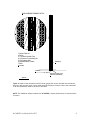
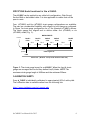
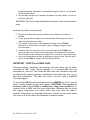
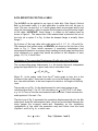
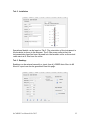
d-CABLE – User Manual YieldPoint Inc. Oct 2012 Copyright © 2005 by YieldPoint Inc. The Information contained herein is the exclusive property of YieldPoint Inc., except as otherwise indicated and shall not be reproduced, transmitted, transcribed, stored in a retrieval system, or translated into any human or computer language, in any form or by any means, electronic, mechanical, magnetic, optical, chemical, manual, or otherwise without expressed written authorization from the company. The distribution of this material outside the company may occur only as authorized by the company in writing. YieldPoint hardware and software products are not designed to be used in the diagnosis and treatment of humans. Windows 95/98, NT and XP are registered trademarks of Microsoft Corporation. Modbus is a registered trademark of Modicon Inc. The Bluetooth® word mark and logos are owned by the Bluetooth SIG, Inc. Warranty and Service Policy Product Warranty YieldPoint Inc warrants the instruments described in this manual to be free from defects in materials and factory workmanship to the original buyer. This warranty is contingent upon proper use of the equipment, and does not cover equipment that has been modified or has been subjected to abusive physical or electrical stresses. YieldPoint Inc., agrees to repair or replace, at its sole discretion, any instrument that fails to perform as specified within 6 months after date of the original shipment from the factory, or 3 months after the date of installation, whichever date comes first. Yieldpoint Inc., reserves the right to make substitutions and modifications in the specifications of equipment that do not materially or adversely affect the performance of the equipment. New equipment may be returned within 30 days of shipment with prior approval. New items which are less than thirty days old after shipment may be returned for credit, less a minimum restocking and testing charge of twenty percent of the list price upon factory approval only, provided the customer pays all shipping and handling charges. Specially ordered, or modified goods, or goods which have been used or have been unpacked, or goods which have been shipped more than thirty days prior are not returnable. The information contained in this manual is subject to change without notice. YieldPoint Inc. makes no warranty of any kind with regard to this material, including, but not limited to, the implied warranties of merchantability and fitness for a particular purpose. Further, YieldPoint Inc., assumes no responsibility for any errors that may appear in this manual and makes no commitment to update, or keep current, the information contained in this manual. Service Policy Units within the warranty period returned for repair, test, and recalibration are serviced at no charge in accordance with the terms of the warranty policy. The Customer pays all transportation and other charges to the factory. Units out of warranty returned for repair, test, and/or recalibration are handled on a time and material basis. If requested, or if costs exceed 50% of current list price, YieldPoint Inc., advises the customer prior to making the repairs. Such repairs are performed at the customer’s expense. Typical test, recalibration, and repairs are 25% of the instrument’s current list price. Transportation charges both ways are at the customer’s expense. Please be sure all returns are shipped with the following information included: 1.Your company Name with Billing and Shipping Addresses. 2.A complete description of your problem, or re-calibration data. 3.The contact person at your company, with their telephone and facsimile numbers. 4.Non-Warranty returns additionally need your Purchase Order Number. Please pack your returned instruments in their original shipping cartons, or in equivalent strong protective shipping cartons. d-CABLE User Manual Oct 2012 2 The d-CABLE The d-CABLE is based on a miniature inductive strain gauge (Figs 1 and 2) small enough to be recessed into a surrogate tubular king-wire. When the ends of the strain gauge are secured (swaged) at specified nodes within the king-wire the instrumentation will measure how a certain length of the cable bolt is stretching in response to loading(Fig. 2). Either a single gauge (for end anchored cables spun in resin) or an array of such strain gauges may be specified. They may be concentrated at locations where it is predicted that the cable may intersect a known geological structure. Since the strain gauges are distributed along the cable rather than being housed in an instrumentation head, the “signal processing head” of the d-CABLE can be reduced to a diameter almost equal to the diameter of the cable. Consequently the cable can de more easily used in situations that require plating or pre-tensioning. The output signal from the d-CABLE is a digital signal RS485 serial (9600,8,N,1) signal with the Serial Number, Sensor Type and data multiplexed on a single twisted pair. The reading comprises multiple values (one for each strain gauge) directly in tons so that the user has a direct and immediate indication of cable load without having to enter the data in a spreadsheet. SWAGE BL SWAGE Figure 1. The ends of the strain gauge are swaged to the tubular kingwire at Nodes. The strain multiplied by the stiffness factor of the cable provides a measurement directly in tons. d-CABLE User Manual Oct 2012 3 DISPLACEMENT SENSOR DETAIL 5 3 1 5 2 7 8 6 4 3 1 1.Carbon Fiber rod 2.Ferrite 3. Thin Wall PolyImide Tube 4. Coil wound on polyimide tube 5. SS tempered tube 6.Peripheral wires of cable 7.Rock 8.Cement Borehole Leadwire Signal processing and telemetry assesmbly. 300mm Figure 2: Detail of the miniature inductive strain gauge that can be recessed into the tubular king-wire such that the strain can be determined accurately at location rather than translated to an instrumentation head at the end of the cable. NOTE: The YieldPoint manual readout unit (d-READER ) outputs load directly in tons(resolution 0.01tons). d-CABLE User Manual Oct 2012 4 How is the DETECT Cable different (compare with US patent # 5,929,341)? The instrumented cable bolt outlined by Bawden and Hyett (US patent 5,929,341) describes a load measuring device which comprises rock support means having an internal longitudinal cavity extending through it such as to accommodate a plurality of rigid wires each of which is anchored at a predetermined anchor point within said cavity and at its other end is connected to a longitudinally moveable spring loaded actuator provided with an electrical contact to a linear displacement sensing means. To all intents and purposes the design is a miniature multi-rod borehole extensometer built into the king-wire of the cable. In US patent 5,929,341 the instrument output signal is a series of voltages (directly proportional to mm of movement) that are transmitted on different conductors, and the load can be determined from the strain (difference in voltage between adjacent nodal points) multiplied by a stiffness factor. Therefore each strain (i.e. load) determination depends on two adjacent displacement measurements so that an error in one will result in a spurious interpretation of load - usually one load point will be too low and the adjacent load point will be too high or vice-versa). To further complicate matters for the design in US patent 5,929,341 the displacements are measured relative to the instrumentation head at the end of the cable, and which may move independently of the cable. In contrast, the d-CABLE comprises an array of independent miniature strain gauges (described above) within the cable by securing both ends of a miniature strain gauge to the tubular kingwire. Each strain gauge provides a definitive measurement of strain from which the Load(in tons) can be computed directly. The SMART cable design in US patent 5,929,341 has a number of additional disadvantages: (i)The displacement must be translated from a predetermined point within the cable to the instrumentation head by the spring loaded wire, and is susceptible to thermal variations and cable flexure. For example the reading will vary as the cable is coiled for transportation and on uncoiling hysteresis (i.e. non-recovery of this effect due to friction in the system) will cause initial readings at low loads to be unpredictable. (ii) The voltage readings need to be processed in a spreadsheet prior to interpretation. This prevents instantaneous manual interpretation of load (i.e. Factor of Safety) and the use of local alarm systems. (iii) The strain at critical points in the cable bolt may be underestimated because of the long strain base-length (typically >1m). This is a potentially important problem in massive blocky ground where deformations may be concentrated at a single discontinuity or crack. The resolution of the potentiometers and other associated inaccuracies prevent better resolution. (iv) The potentiometer displacement transducers are inaccurate (linearity 5%FS) and are susceptible to water and blast damage. (v) The analog voltage signal transmitted is not suitable for the harsh mining environment. d-CABLE User Manual Oct 2012 5 SPECIFYING Nodal Locations for the d-CABLE. The d-CABLE can be applied to any cable bolt configuration: Plain Strand, Garford Bulb or de-bonded cable. It is also applicable to cables that will be spun in resin. Four (d4CABLE) and five (d5CABLE) strain gauge configurations are available. The user has considerable flexibility with respect to how these are configured. In Figure 3 a strain gauge configuration for a 7.5m (Nominal) d4CABLE is shown. The strain gauges are aligned end to define either five (d4CABLE) or six (d5CABLE) nodes (Fig. 3). NODAL POINTS Leadwire Node 1 0.3m Node 2 1.7m 3.5m 0m SG SG#11 Head Meas.Load (0.35m) Gauge Disp 0.0m (mm) Disp fromHead (mm) Node 3 3.1m 7.0m SG2#2 SG Node 4 4.5m SG 3SG #3 1.90tons 1.20tons 7.80tons Cable length 6.95 2.22mm 1.40mm 9.10mm Node5 6.7m 10.5m SG 4SG #4 14.0m 13.20tons 11.2mm 0.3m Actual 7.3m / Nominal 7.5m (0.2m for borehole under-drill) 2.22mm 3.62mm 12.72mm 23.92mm Figure 3. The strain gauge layout for a d4CABLE. When the four(4) strain gauges are arranged end-to-end they define five(5) Nodes. NOTE: The maximum strain gauge length is 5000mm and the minimum 200mm. CALIBRATION SHEETS Every d_CABLE is individually calibrated to approximately 50% of cable yield. The calibration data is available online form the following link. http://www.yieldpoint.com/cal_reports.php d-CABLE User Manual Oct 2012 6 INSTALLATION OF THE d-CABLE If there is no need to install a face-plate on the d-CABLE then it can be installed just as regular cable-bolt (Option 1 in Fig. 4) If a faceplate must be installed it important to inform YieldPoint Inc. when the instrument is ordered. The most effective strategy for installing a faceplate is to recess the instrumentation head to the toe of the borehole and retrieve the lead-wires through a continuous steel conduit. The head of the d-CABLE and the steel conduit are united at a friction coupling consisting of a capped length of CPVC tube. The steel conduit is attached to the cable with the BLACK cable ties which should not be removed during installation. A slotted plate is provided through which to run the conduit. Figure 4. The 3 possible options for installing a d-CABLE. Option 1 is unplated and Option 3 is the preferred option for a plated cable. Uncoiling the cable. 1. Plug the cable into the d-READER and take a reading with the instrument coiled. The instrument will scroll through its anchors. 2. Cut the smaller white cable ties to release the regular leadwire from the cable. 3. Holding the head of the cable carefully cut the large white cable ties beginning at the toe of the cable. This is most easily accomplished with the cable in an d-CABLE User Manual Oct 2012 7 upright orientation. Remember: considerable energy is stored in a coiled cable so care must be taken. 4. Lay the cable straight and if necessary straighten the steel conduit. Do not cut the black cable ties. IMPORTANT: The Yellow tape indicates the end-point of the instrumentation array. Installing the cable in the borehole: 5. Blow all down-holes and in general make sure the holes are as clean as possible. 6. In poor ground insert a regular (non-instrumented) cable and grout hose to make sure the borehole is viable. 7. Cut a length of grout hole to the appropriate length for the d4CABLE . Remember to cut the end of the grout hose at a 60degree angle to make insertion easier. 8. Securely attach the grout hose to the instrumented end of d4CABLE with electrical tape (toe to collar grouting assumed). The angled end of the grout hose should be within 150mm of the capped CPVC tube at the instrument head. 9. Insert into the borehole carefully by pushing on the grout hose. Tape the grout hose to the d4CABLE at regular intervals during insertion. IMPORTANT – ZERO The d-CABLE LOAD Following shipping, installation and grouting, the load values may be offset compared to their initial factory readings. It is recommended that the instrument be “zero-ed”.This should be done after the instrument has been installed and the cement grout has completed its early exothermic cure ( e.g. 2 days after installation). The cable can only be “zero-ed” using a d_READER (not a datalogger). To zero the d-CABLE plug the instrument into the d-READER for up to 2 min (at least 8 reading samples on each strain gauge). IMPORTANT: This operation is necessary even if the d-CABLE is reading zero values after installation. In versions of the d-CABLE with IDs more recent than 1208xxxxx then the cable will register compression (-ve values) which may occur after the cable is uncoiled. These values are intended primarily as a visual cue since their values will revert to 0.00 tons after the instrument is properly zeroed. d-CABLE User Manual Oct 2012 8 DATA REDUCTION FOR THE d-CABLE The d-CABLE can be applied to any type of cable bolt: Plain Strand, Garford Bulb or de-bonded cable. It is also applicable to cables that will be spun in resin. The user can specify 4 or 5 strain gauges which are arranged end-to-end along the instrument in order to capture the elongation along the entire length of the cable. IMPORTANT: Strain Gauge 1 is closest to the readout head as shown in Figure 3. This means that if the readout head is placed at the toe of the hole (As in option 3 in Fig. 4) then the deepest Gauge is actually Strain Gauge 1. Fig 5 shows a 7.0m long cable with nodal points at 0.3, 1.7, 3.1, 4.5 and 6.7m. The measured load values (using a d-READER) are shown on the top line of the table in Fig. 5. These values represent 4 completely independent load measurements based on an average strain reading for each gauge and therefore when displayed on a graph they should be plotted at the midpoint of each gauge, 1.0, 2.4, 3.8 and 5.6m. Calculation of Corresponding Displacement Profile along the Cable Bolt The corresponding gauge displacement (i.e. the stretch that each independent gauge has experienced for a given load) can be calculated from: n = (Fn x Ln)/kcab Eqn 1. Where Fn is the output value from the nth strain gauge in tons, kcab is the stiffness of the cable ( 3tons/mm/m) and L n(in m) is the length of the gauge. kcab, the cable stiffness, is the load required to stretch a 1m length of cable by 1mm. The second row of Fig. 5 is the displacement for each strain gauge in mm calculated from Eqn 1. For SG 1 the calculation for is (10.7/3.0)*1.4=5.0mm e.g. for 10.7tons of load the instrumented cable stretches 5.0mm between the nodal points at 0.3m and 1.7m. The third row of Fig. 5 represents the cumulative displacement (dN) for the Nth nodal point along the instrumented cable, which can be calculated because the strain gauges are arranged end-to-end. Depending on the installation configuration of the cable the summation may start either from the head (Options 1 and 2 in Fig. 4), in which case: dN = n + dN+1 d-CABLE User Manual Oct 2012 Eqn. 2 (Options 1 and 2) 9 Figure 5: Configuration, Load measurement and corresponding displacements along a d-CABLE. or toe (Option 3 in Fig. 4) of the instrument: dN = dN-1 + n Eqn 3. (Option 3) Assuming for example that the d-CABLE is installed with the head at the collar of the borehole (Option 1 in Fig. 4) then Eqn. 2 applies. The toe of the instrument will represent the displacement reference point: dN=5 = 0.0mm. For Node 4 the displacement is: dN=4 = n=4 + dN=5 = 0.2mm and for Node 3: dN=3 = n=3 + dN=4 = 1.2mm And so on, along the cable. The index N refers to the nodal points while the index n refers to the strain gauge number. Obviously the calculation of these values is tedious and therefore YieldPoint provides an easy to use analysis package called MineScope CABLE. d-CABLE User Manual Oct 2012 10 ANALYSIS USING MineScope CABLE MineScope CABLE can be downloaded from the following webpage: http://www.yieldpoint.com/minescope.php The software will conduct all the calculations outlined above, visually present the data and provide reports. d_LOG datafiles can be automatically imported into MineScope_CABLE. YieldPoint or one of our distributors can be contacted for a customized MineID to replace DEMO. Tab 1. Identification The d_CABLE ID and configuration data should be input. The Instrument length, installation details and Swage/Nodal points are entered in the appropriate boxes. For d-CABLEs with IDs more recent than 1208xxxxx this information is included on the calibration sheet. d-CABLE User Manual Oct 2012 11 Tab 2. Installation Operational details can be input on Tab 2. The orientation of the instrument in the borehole is shown in the diagram. The 0.35m recess reflects that the instrumentation head has been recessed into the borehole collar so the actual cable starts at 0.35m from the collar. Tab 3. Readings Readings can be entered manually or input from d_LOGGER data-files. An MS WordTM report can also be generated from this page. d-CABLE User Manual Oct 2012 12 Tabs 4 - 5 Temporal plots Temporal plots of Load(tons) and Displacement(mm) are shown on Tabs 4 and 5. Each trace represents a different strain gauge. The Node locations are relative to the borehole collar. Each trace represents a different Nodal Point. The Node locations are relative to the borehole collar. d-CABLE User Manual Oct 2012 13 Tabs 6 - 7 Spatial plots The distribution of load and displacement along the d-CABLE length are shown on Tabs 6 and 7. Each trace corresponds to a given reading date. It should be recognised that the distribution of load and corresponding displacement (d) along the cable are quite different: the load (F in tons) being proportional to the slope of the displacement plot multiplied by kcab. It should also be noted that the Load values are plotted at the Strain Gauge Centers and the Displacement values at the intervening Nodes. In the case where the cable is unplated the load must be zero at both ends of the cable. d-CABLE User Manual Oct 2012 14 TYPICAL APPLICATIONS d-CABLE have been widely used for many application in both civil and mining projects including: Slope monitoring. Monitoring cable reinforcement in tunnels and drifts Monitoring cable reinforcement in stopes and other large openings Monitoring cables in fill mats Monitoring ground anchors Monitoring strand reinforced concrete Monitoring tie-backs 2 Load tonnes ) 1.5 Anchor4 Anchor 3 Anchor 2 1 Anchor 1 Temp Change(C) 0.5 0 Temp(C) -0.5 -1 -1.5 -2 200 220 240 260 280 300 320 340 360 380 Time (hours) In all cases monitoring with d-LOGGERs add significant value to the project. d-CABLE User Manual Oct 2012 15