1
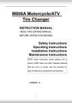
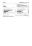
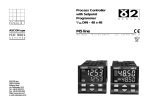
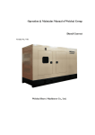
User Manual for SJ Series Metering Pump
Professional Metering Pump Manufacturer
Shanghai Shenbei Pump Manufacture Co., Ltd
CONTENTS
SJ Series Metering Pump
Professional designs
Professional manufacturing
Overview
02
Configuration Principle
03
Installation Requirements
07
Users’ Guide
07
Maintenance and Disassembly
and Assembly of Pumps
08
Trouble-Shooting Table
10
www.sbpump.com
SJ Series Metering Pump
Overflow
SJ series of metering pumps are used to non-leakage delivery of various corrosive and hazardous liquids. Their
technical parameters and inspection specifications stringently comply with GB/7782-1996 for metering pumps.
Metering pumps, with a flow rate of 0.2-50000L/h and pressure of 0.25-50MPa, are divided into plunger
metering pumps and diaphragm metering pumps in terms of liquid end.. However, when measured by stands,
they can be divided into 14 series: SJ1, SJ2, SJ3, SJ4, SJ5, SJ6, SJ7, SJ1-M, SJ2-M, SJ3-M, SJ4-M, SJ5-M, SJ6-M and
SJ7-M. Users usually choose metering pumps based on their simplex parameters. In addition, they can also choose
a multiplex combination of metering pumps with uniform stands and specifications or a combination of those
with different stands and specifications. These series are especially suitable for the propotioning delivery of
various media in process flows, to accommodate their needs.
There are two ways to adjust the flow rate of metering pumps. One is to change the length of the plunger
stroke (the optimal relative stroke length is 30-100%) with measuring accuracy of ±1%, whenever the pump halts
or operates; while the other one is to regulate the input frequency of power supply with a transducer to adjust the
pump speed.
Metering pumps are used to deliver liquids without solid particles, with temperature of -30-100℃ (up to 300℃
for special liquids) and viscosity of 0.3-800mm2/s. Thanks to their non-leakage advantages, diaphragm metering
pumps can be leveraged to deliver inflammable, explosive, volatile, highly corrosive, radioactive, deadly poisonous,
suspending as well as expensive fluids.
Type and Specification Compilation Description
Enterprise logo Frame cushion number
Insulation
Flow
2 S J 3 - M - 100 / 0.5 - B - P
Quantity cylinder
Diaphragm
Pressure
Material
Metering pump
2
专业的计量泵制造
www.sbpump.com
SJ Series Metering Pump
Configuration Principle
A finished metering pump consists of motors, driving end and fluid end.
1. Driving end
Principle for deceleration and adjustment of driving end:
The motor slows down with the functioning of the worm gear. The spool, eccentric wheel and
coupler constitute the crank mechanism. This, together with the crosshead, results in the The plunger stroke
adjustment mechanismis composed of spool, adjusting screw nuts, adjusting screws, handwheel, pointer and
scale. It can directly adjust the relative stoke of the plunger.
2. Fluid end
2.1 Plunger-type fluid end
1) fluid-end structure of plunger metering pumps
The fluid end of plunger metering pumps (refer to Figure 1) mainly composes of plunger, cylinder
block, inlet and outlet valves and stuffing seal.
2) Principle for fluid end of plunger metering pumps:
The plunger connects the crosshead, and the reciprocating movement of the crank-connecting rod
mechanism facilitates the operation. When the plunger moves to the left (intake stroke), the cylinder block
becomes vacuum with the outlet valve tightly closed and the inlet valve automatically opens,and then medium
enters the cylinder block in tandem with a change in differential pressure; when the plunger moves to the right
(discharge stroke), high pressure is formed in the cylinder block with the inlet valve tightly closed and the outlet
valve forced to open as a result of the raised pressure. Then the medium enters the flow pipe in tandem with
change of the differential pressure, realizing medium delivery.
Figure 1 Structural schematic view for plunger-based fluid end
3
专业的计量泵制造
www.sbpump.com
SJ Series Metering Pump
Configuration Principle
2.Disassembly and assembly
2.1Disassembly of fluid end of plunger metering pumps
Move the plunger forward to the dead point and remove from the crosshead. After dismantling the suction
and discharge pipe flange, remove the flange nuts, and dismantle the entire fluid end from the stand. Then
dismantle all the parts in the hydraulic cylinder sequentially as follows:
(A) Pull out the plunger to dismantle the gland cover, and then take out the stuffing seal, shaft seal and
plunger bushing;
(B) Dismantle suction pipe flange, and then take out the valve barrel, valve ball and valve seat.
2.2 Disassembly of fluid end of diaphragm metering pumps
Screw the inside hexagon bolt at the bottom of the bracket to let out the hydraulic oil. Turn the coupling of
the motor to move the plunger forward to the dead point and then remove from the crosshead. After dismantling
the fluid end from the stand, dismantle parts of the fluid end sequentially as follows:
(A) Dismantle safety air vent and surge valves;
(B) Dismantle inlet and outlet valve flange, and then take out the valve barrel, valve ball and valve seat;
(C) Screw the nuts on the cylinder head to dismantle it, and then take out diaphragm;
(D) Dismantle the bolts used to fasten the cylinder block and the bracket, and then take out the cylinder
block, plunger, hydraulic cylinder and finally the limit valve components;
(E) Dismantle the nuts connecting the bracket and gear box and then take out the bracket.
2.3 Follow orders below to assemble it:
(A) Assemble the fluid end of plunger metering pumps on the driving stand by means of the reverse order
for disassembly of it;
(B) Assemble the fluid end of diaphragm metering pumps on the driving stand by means of the reverse
order for disassembly of it. Adjust the oil-filling valve set and safety and air vent valve set, and before assembling
the air vent and safety valves, fill enough hydraulic oil to exhaust the air in the in the hydraulic pressure cavity.
During the trial operation, the coupling should be able to work smoothly without any block and jam.
2.2 Diaphragm-type fluid end
1) Structural principle for diaphragm metering pumps
The fluid end of diaphragm metering pumps (Figure 2) is mainly composed of plunger, cylinder block,
cylinder head, inlet and outlet valves, diaphragm and three valves (safety valve, air vent valve and surge valve).
During operation, diaphragm can block off hydraulic oil and medium, as a result, diaphragm metering pumps
boast fully leak-tight advantages, building up their position as an ideal tool to deliver inflammable, explosive,
volatile, highly corrosive, radioactive, deadly poisonous, suspending and expensive fluids.
The fluid end plunger of diaphragm metering pumps is driven by the reciprocating movement of the crankconnecting rod mechanism at the driving end. The reciprocating movement of plunger in the hydraulic pressure
cavity increase pressure of the hydraulic oil to deliver medium by deflection of the diaphragm. The stable volume
of hydraulic oil in the hydraulic pressure cavity is maintained by the three valves. The air vent and safety valves (refer
to
专业的计量泵制造
4
www.sbpump.com
SJ Series Metering Pump
Configuration Principle
Figure 3) will be able to let out the air in the hydraulic pressure cavity from the hydraulic oil, ensuring smooth
operation, while avoiding the adverse effect of automatic oil discharge arising from excessive pressure caused by
overfull hydraulic oil or a blocked drainage pipe. Leveraging the diaphragm to drive the span of the limit valve,
the limit surge device (refer to Figure 4) will be able to renew oil according to the vacuum degree in the hydraulic
pressure cavity, ensuring the fullness of hydraulic oil in the cavity.
2) Adjustment for safety valve opening pressure
Safety valve has been checked according to rated discharge pressure before leaving the factor. Should there
be any variance between the actual and rated discharge pressure, please adjust it according to the following table:
Unit:MPa
Actual discharge pressure P
0.2~1.0
1.3~4.0
5.0~8.0
10.0~16.0
Safety valve opening pressure P1
p+0.3
1.3p
1.2p
1.1p
5
Figure 2: Structural schematic view for diaphragm-based fluid end
专业的计量泵制造
www.sbpump.com
SJ Series Metering Pump
Configuration Principle
Figure 3 Air vent and safety valves
Figure 4 Limit surge device
安全阀
脉动阻尼器
压力表
液
位
计
背压阀
出口
储药箱
取样口
截止阀
计量泵
Y型过滤器
6
Figure 5 Work flow chart
专业的计量泵制造
www.sbpump.com
SJ Series Metering Pump
Installation Requirements
1. The pump should be mounted on a dedicated concrete foundation or steel platform, and fastened with
anchor bolts after emendation. The concrete foundation should be 50-100mm above the ground.
2. Diameters of the suction and discharge pipes should be not less than those of the inlet and outlet
pipes, and try hard to shorten the suction pipe . If the suction pipe is too long or there are too many angular pipe
unions, an NPSHa calculation is needed, so as to meet the needs of the net positive suction head.
3. Measuring instruments, such as pressure gauges (self-prepared by users) should be installed in the
connecting pipe.
4. Filter devices (self-prepared by users) should be mounted at the end of the suction pipe.
5. Safety valves or safety relief valves (self-prepared by users) should be mounted in the discharge pipe.
Pressure stabilizers (self-prepared by users) may be mounted near the pump’s discharge pipe to reduce exit
pressure fluctuation if necessary.
6. Control equipmet of Electric appliance, which should better be mounted at the working location of the
pump, is called to be equipped with switch protection device in line with medium delivery, so as to ensure safety.
7. For multiplex pumps (plunger metering pumps or diaphragm metering pumps) with uniform stands and
specifications, pipe installation should be based on process flows and pressure ratings (follow a high-low order),
while starting from the motor; for those with different stands and specifications and following a high-low order in
installation, all the users have to do is to connect pipes.
8. Other technical requirements for pump installation should be in compliance with Code for construction
and acceptance of mechanical equipment installation engineering (TJ231 (5)-78).
9. Please see the installation dimension diagram for external dimensions and installation dimensions of
pumps.
Users' Guild
1.Preparation before pump operates
Before the pump operates, check to ensure that all connecting bolts and nuts are tightly fastened. Use coal
oil to scrub away the anticorrosion greases or dirt attached on the new pump. Do remember not to scrape with a
knife.
Pour into the driving box appropriate L-CKE460 worm gear oil (SH/T0094-1991) or L-CKC460 industrial closed gear
oil (GB5903-1995), and the oil level should reach the horizontal midline.
Pour appropriate L-HM46 hydraulic oil into the hydraulic oil tank of diaphragm metering pump, and the oil
level should reach the horizontal midline or the oil line.
Turn the coupling to make the plunger move to and fro without any block and jam. Connect the power
supply to start the motor, which should rotate in the same direction as the arrow plate of the pump. The inlet and
7
outlet valves on the pipe should be fully open.
2. Adjustment for flow rate of pumps
In line with requirements of the process, check the calibration curve to get a value, and then adjust the
adjusting quantity meter to the corresponding value. The flow-rate should be adjusted in the low-high direction.
专业的计量泵制造
www.sbpump.com
SJ Series Metering Pump
Should a high-low direction be needed, pay attention to the rotation of the pointer, and when the pointer
reach the position required and see an overrun, adjust the pointer to the required numerical value. Lock the
adjusting turntable when the adjustment finished.
Adjust stoke of the pump during halt or operation. After the adjustment, it takes some one to two minutes
for the pump to see a stable flow-rate. The greater the stroke length changes, the longer it will take for a stabilized
flow-rate to be seen.
3.Operation of pumps
When the above work finishes, start the motor and the pump will work.
4.Halt
First of all, keep the outlet throttle valve fully open, and reduce to constant pressure by discharging pressure.
Then, cut off power supply to halt operation of the motor.
Maintenance and Disassembly and Assembly of Pumps
1.Maintenance
Gear box and hydraulic oil box should keep amount of oil as appointed. Lubricating oil and hydraulic oil
should be pure and replaceable according to the cycle listed below:
Term for change of lubricating oil
Term of use
Oil change cycle
Oil change cycle
Every 3 months
Every 3 months
Every 6 months
After operation for 2,000-3,000 hours, disassemble the pump to examine parts inside and replacevenerable
components.
Should the pump not operate for a long period, drain away the medium in the hydraulic cylinder, clean its
surface and daub rust preventive oil on the surface. During the store period, the pump should be kept in a dry
place and enveloped with a cover.
2.Disassembly and assembly
2.1Disassembly of fluid end of plunger metering pumps
Move the plunger forward to the dead point and remove from the crosshead. After dismantling the suction
and discharge pipe flange, remove the flange nuts, and dismantle the entire fluid end from the stand. Then
dismantle all the parts in the hydraulic cylinder sequentially as follows:
(A) Pull out the plunger to dismantle the gland cover, and then take out the stuffing seal, shaft seal and
plunger bushing;
(B) Dismantle suction pipe flange, and then take out the valve barrel, valve ball and valve seat.
2.2 Disassembly of fluid end of diaphragm metering pumps
Screw the inside hexagon bolt at the bottom of the bracket to let out the hydraulic oil. Turn the coupling of
专业的计量泵制造
8
www.sbpump.com
SJ Series Metering Pump
the motor to move the plunger forward to the dead point and then remove from the crosshead. After dismantling
the fluid end from the stand, dismantle parts of the fluid end sequentially as follows:
(A) Dismantle safety air vent and surge valves;
(B) Dismantle inlet and outlet valve flange, and then take out the valve barrel, valve ball and valve seat;
(C) Screw the nuts on the cylinder head to dismantle it, and then take out diaphragm;
(D) Dismantle the bolts used to fasten the cylinder block and the bracket, and then take out the cylinder
block, plunger, hydraulic cylinder and finally the limit valve components;
(E) Dismantle the nuts connecting the bracket and gear box and then take out the bracket.
2.3 Follow orders below to assemble it:
(A) Assemble the fluid end of plunger metering pumps on the driving stand by means of the reverse order
for disassembly of it;
(B) Assemble the fluid end of diaphragm metering pumps on the driving stand by means of the reverse
order for disassembly of it. Adjust the oil-filling valve set and safety and air vent valve set, and before assembling
the air vent and safety valves, fill enough hydraulic oil to exhaust the air in the in the hydraulic pressure cavity.
During the trial operation, the coupling should be able to work smoothly without any block and jam.
hydraulic pressure cavity. During the trial operation, the coupling should be able to work smoothly without
any block and jam.
3.Supply Range of Complete Set
3.1. One metering pump
3.2. One motor
3.3. Inlet and outlet flange (special orders)
3.4. Accessories and spare parts (special orders)
3.5. Packing list
3.6. Instructions and quality certificate of products
9
专业的计量泵制造
www.sbpump.com
SJ Series Metering Pump
Trouble-Shooting Table
Serial
No.
Malfunction
1
No liquid
discharge at all
1. Too high suction height
2. Blocked suction pipe
3. Air leakage in suction pipe
1. Reduce installation height or
reduce number of elbow valves
2. Clean and dredge suction pipe
3. Press out or replace flange
gaskets
Inadequate
liquid discharge
1. Suction pipe is partially blocked
2. Blocked sundries in suction or
discharge valve
3. Air left in oil filling cavity
4. Insufficient or excessive oil in oil
filling cavity
5. Oil leakage in surge valve or
safety valve
6. Closure lax caused by worn
pump valves
7. Insufficient rotation rate
1. Clean and dredge suction pipe
2. Clean suction and discharge
valves
3. Manual oil filling to force safety
valve to discharge oil
4. Complement and fill or
discharge oil manually
5. Grind the valve
6. Repair or replace valve parts
7. Examine motor and voltage
1. Blocked sundries in suction or
discharge valve
2. Oil leakage at joint of
diaphragm limit board or
discharge pipe
3. Safety valve or surge valve
malfunction
1. Clean suction and discharge
valves
2. Screw down joint bolts
3. Adjust safety valve or surge
valve
Inadequate
measuring
accuracy
1. Residual air left in oil filling
cavity
2. Safety valve or surge valve
malfunction
3. Oil leakage at plunger seal
stuffing
4. Permanent deformation of
diaphragm
5. Worn suction or discharge valve
6. Unstable rotation rate of motor
1. Manual oil filling to force safety
valve to exhaust air
2. Adjust safety valve or surge
valve
3. Adjust or replace seal ring
4. Replace diaphragm
5. Replace new parts
6. Stabilize power supply
frequency and voltage
5
Impulsive sound
during operation
1. Loosened or badly worn driving
parts
2. Too high suction height
3. Air leakage in suction pipe
4. Excessive oil in diaphragm
cavity
5. Air left in medium
6. Diameter of suction pipe too
short
1. Tightly Screw related bolts or
replace new parts
2. Lower installation height
3. Press out suction flange
4. Gently press surge valve to
discharge oil manually
5. Exhaust air in medium
6. Enlarge diameter of suction pipe
6
Delivery medium
oil polluted
1. Cracked diaphragm
1. Replace new parts
2
3
4
Unstable pressure
discharge
Cause
Trouble-shooting
10
专业的计量泵制造
www.sbpump.com
www.sbpump.cn
上海申贝泵业制造有限公司
Shanghai Shenbei Pump Manufacture Co., Ltd.
地址(Address):上海市万荣路839号
839 Wanrong Rd, Shanghai
电话(Tel):
86+21-56034268 56652308
传真(Fax):
86+21-56652046
网址(Web):
www.sbpump.com www.sbpump.cn
电邮(E-mail): [email protected]
申贝泵业始终致力于水泵领域的研究与创新,个别尺寸如有变动,恕不另行通知。
Shenbei pump has always been devoting to reseach and innovation of pump,any individual specification is
subject to change without notice.