1
m
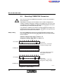
User Manual
s.
co
Configuring and Installing INTERBUS
Designation: IBS SYS PRO INST UM E
on
l
in
ec
om
po
ne
nt
Order No.:
27 43 80 2
s.
nt
ne
po
om
in
ec
on
l
co
m
Revision:
AC02
Order No.:
27 43 80 2
nt
IBS SYS PRO INST UM E
in
ec
om
po
ne
Designation:
s.
co
m
Configuring and Installing INTERBUS
User Manual
This manual is valid for:
– ST modules (Smart Terminals)
– RT modules (Remote Terminals)
on
l
– CT-I/O gateways (Configurable Terminals)
– Sensor/actuator boxes (SAB)
– 500 V version of the INTERBUS motor starter
© PHOENIX CONTACT 11/2001
6000AC02
s.
nt
ne
po
om
in
ec
on
l
co
m
Please Observe the Following Notes:
In order to guarantee the safe use of your device, we recommend that you
read this manual carefully. The following notes give you information on
how to use this manual.
m
Requirements on the User Group
nt
s.
co
The use of products described in this manual is oriented exclusively to
qualified electricians or persons instructed by them, who are familiar with
applicable national standards. Phoenix Contact assumes no liability for
erroneous handling or damage to products from Phoenix Contact or external products resulting from disregard of information contained in this manual.
ne
Explanation of Symbols Used
po
The attention symbol refers to an operating procedure which, if not carefully followed, could result in damage to equipment or personal injury.
om
The note symbol informs you of conditions that must strictly be observed
to achieve error-free operation. It also gives you tips and advice on hardware and software optimization to save you extra work.
in
ec
The text symbol refers to detailed sources of information (manuals, data
sheets, literature, etc.) on the subject matter, product, etc. This text also
provides helpful information for the orientation in the manual.
We are Interested in Your Opinion
on
l
We are constantly attempting to improve the quality of our manuals.
Should you have any suggestions or recommendations for improvement
of the contents and layout of our manuals, we would appreciate it if you
would send us your comments. Please use the universal fax form at the
back of the manual for this.
Statement of Legal Authority
This manual, including all illustrations contained herein, is copyright protected. Use of this manual by any third party in departure from the copyright provision is forbidden. Reproduction, translation, or electronic or
photographic archiving or alteration requires the express written consent
of Phoenix Contact. Violators are liable for damages.
6000AC02
IBS SYS PRO INST UM E
Phoenix Contact reserves the right to make any technical changes that
serve the purpose of technical progress.
Phoenix Contact reserves all rights in the case of patent award or listing of
a registered design. External products are always named without reference to patent rights. The existence of such rights shall not be excluded.
Internet
on
l
in
ec
om
po
ne
nt
s.
co
m
Current product information is also available on the Internet at
www.phoenixcontact.com.
6000AC02
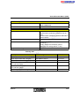
Table of Contents
1 INTERBUS System Basics ..............................................................................1-3
About This User Manual..............................................................1-3
1.2
Relevant Standards.....................................................................1-5
1.3
Introducing the INTERBUS System ...........................................1-6
1.4
Overview of the Product Families .............................................1-20
1.5
INTERBUS Software.................................................................1-26
1.6
INTERBUS Addressing .............................................................1-29
1.7
Conformance with EMC Directive
89/336/EEC...............................................................................1-30
ne
nt
s.
co
m
1.1
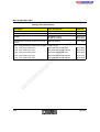
2 INTERBUS Installation .....................................................................................2-3
Note.............................................................................................2-3
2.2
Installation Information ................................................................2-5
2.3
Grounding Concept .....................................................................2-6
Installing Bus Lines Between Buildings.......................................2-7
Interference Suppression Measures ...........................................2-9
on
l
in
ec
2.6
om
2.5
po
2.1
2.7
Power Supply of Bus Terminal Modules (BK Modules) ............2-10
2.8
Connection of Digital Sensors and Actuators............................2-11
2.9
Assembling Standard Connections ...........................................2-19
3 INTERBUS Project Planning ............................................................................3-3
3.1
Bus Cable Selection....................................................................3-5
3.2
INTERBUS Devices for Dimensioning the Bus Structure .........3-11
3.3
Connecting INTERBUS Devices ...............................................3-14
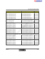
4 ST Modules (Smart Terminals).........................................................................4-3
4.2
6000AC02
Structure......................................................................................4-5
7
IBS SYS PRO INST UM E
4.3
Diagnostic and Status Indicators.................................................4-9
4.4
Mounting ST Modules ...............................................................4-12
4.5
Connecting the Remote Bus .....................................................4-19
4.6
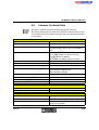
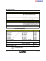
Common Technical Data...........................................................4-25
m
5 RT Modules (Remote Terminals)......................................................................5-3
Structure......................................................................................5-5
5.3
Mounting COMBICON Connectors .............................................5-8
5.4
Diagnostic and Status Indicators...............................................5-10
5.5
Mounting RT Modules ...............................................................5-12
5.6
Connecting the Remote Bus .....................................................5-19
5.7
Common Technical Data...........................................................5-21
ne
nt
s.
co
5.2
po
6 CT-I/O Gateways (Configurable Terminals) .....................................................6-3
Structure......................................................................................6-4
6.3
Diagnostic and Status Indicators.................................................6-7
6.4
6.5
Mounting CT-I/O Gateways.........................................................6-8
Connecting the Remote Bus .....................................................6-10
Common Technical Data...........................................................6-14
in
ec
6.6
om
6.2
on
l
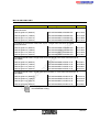
7 Sensor/Actuator Boxes (SAB) ..........................................................................7-3
7.2
Structure......................................................................................7-4
7.3
Diagnostic and Status Indicators.................................................7-6
7.4
Mounting Sensor/Actuator Boxes................................................7-7
7.5
Connecting the Remote Bus and the Supply Lines...................7-10
7.6
Connecting Sensors and Actuators...........................................7-15
7.7
Common Technical Data...........................................................7-16
8 500 V Version of the INTERBUS Motor Starter ................................................8-3
8.1
8
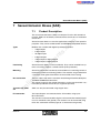
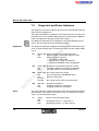
Product Description.....................................................................8-3
6000AC02
Table of Contents
Safety Notes................................................................................8-5
8.3
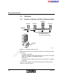
Installation Example ....................................................................8-7
8.4
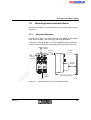
Structure of a Motor Starter.........................................................8-8
8.5
Diagnostic and Status Indicators.................................................8-9
8.6
Mounting Motor Starters............................................................8-11
8.7
Connecting the Bus Cable to the Motor Starter ........................8-15
8.8
Parameterizing the Motor Current (Motor Protection) ...............8-23
8.9
Motor Behavior in the Event of an Error....................................8-26
8.10
Common Technical Data...........................................................8-27
on
l
in
ec
om
po
ne
nt
s.
co
m
8.2
6000AC02
9
on
l
in
ec
om
po
ne
nt
s.
co
m
IBS SYS PRO INST UM E
10
6000AC02
Section 1
This section informs you about
–
working with this user manual
–
the most important INTERBUS data
INTERBUS System Basics ..................................................................................1-3
About This User Manual..............................................................1-3
1.2
Relevant Standards.....................................................................1-5
1.3
Introducing the INTERBUS System ...........................................1-6
1.3.2
INTERBUS System Data .............................................1-10
1.3.3
Transmission Medium..................................................1-14
1.3.4
Data Transmission Method .........................................1-15
1.3.5
Differences Between Generation 3 (G3)
and Generation 4 (G4) .................................................1-17
nt
IBS CMD (G3 and G4) .................................................1-27
om
1.5.2
PC WORX....................................................................1-28
INTERBUS Addressing .............................................................1-29
Conformance with EMC Directive
89/336/EEC...............................................................................1-30
on
l
in
ec
1.7
Explanation of the Product Designation.......................1-23
INTERBUS Software.................................................................1-26
1.5.1
1.6
ne
Overview of the Product Families .............................................1-20
1.4.1
1.5
co
Describing the Bus Components ...................................1-7
s.
1.3.1
po
1.4
m
1.1
6000AC02
1-1
1-2
6000AC02
s.
nt
ne
po
om
in
ec
on
l
co
m
INTERBUS System Basics
1
INTERBUS System Basics
1.1
About This User Manual
m
This manual is for everybody who wants to configure an INTERBUS system. It only describes the product families:
ST modules (Smart Terminals)
–
RT modules (Remote Terminals)
–
CT-I/O gateways (Configurable Terminals)
–
Sensor/actuator boxes (SAB)
–
500 V version of the INTERBUS motor starter
nt
s.
co
–
ne
The first section of this manual introduces you to the INTERBUS basics.
Section 1.3 explains the most important terms.
po
The INTERBUS modules are described in product families (Section 4 to
Section 8). These descriptions contain general information that applies to
each module of the family. If you need specific information on a module
refer to the module-specific data sheets at www.phoenixcontact.com.
om
The index at the end of this manual helps you to get information on a certain topic.
in
ec
Some product families are described in a special system manual. All user
manuals for the product families which are not described here can be
found at www.phoenixcontact.com. You can also order hard copies of the
following system manuals:
–
Configuring and Installing the INTERBUS Inline Product Range
IB IL SYS PRO UM E, Order No. 27 43 04 8
INTERBUS Loop 2
–
Configuring and Installing the INTERBUS Loop 2 Product Range
IB L2 SYS PRO UM E, Order No. 27 43 49 1
INTERBUS Rugged
Line
–
Configuring and Installing the Rugged Line Product Range
IBS RL SYS PRO UM E, Order No. 27 43 78 9
on
l
INTERBUS Inline
6000AC02
1-3
IBS SYS PRO INST UM E
In addition to the system manuals, installation guidelines are also available
for certain motor starters.
Mounting and installation of the steel sheet motor starter
DB GB IBS IP 400 ELR INST, Part No. 90 00 15 9
–
Mounting and installation of the high-grade steel motor starter
DB GB IBS 400 ELR/MLR-F INST, Part No. 90 00 15 7
on
l
in
ec
om
po
ne
nt
s.
co
m
–
1-4
6000AC02
INTERBUS System Basics
1.2
Relevant Standards
The following German and international standards have to be observed for
the installation of an INTERBUS system. Standards or regulations in the
land of application must be followed. In this case the standards listed here
are substituted.
"Erection of power installations with nominal
voltages up to 1000 V"
m
– DIN VDE 0100
co
Part 410 "Protection for safety; protection
against electric shock"
(IEC 60364-4-41, modified)
nt
s.
Part 540 "Selection and erection of equipment;
earthing arrangements, protective
conductors, equipotential bonding
conductors" (IEC 60364-5-54)
"Insulation coordination for equipment within
low-voltage systems" (IEC 60664- 1, modified)
po
– DIN VDE 0110-1
ne
Part 707 "Earthing requirements for the installation of data processing equipment"
om
– DIN VDE 0160
"Lightning protection systems" - Part 1: "General
with regard to installation" (DIN 57185-1)
– DIN VDE 0470-1
"Degrees of protection provided by enclosures
(IP code)" (IEC 60529, EN 60529)
in
ec
– DIN VDE 0185-1
on
l
– DIN EN 50100-1
6000AC02
"Electronic equipment for use in electrical power
installations" (DIN EN 50178)
"Safety of machinery - electrosensitive protective
equipment; general requirements and tests"
Operations and procedures that are not standardized have to be carried
out according to the current state of technology and safety.
1-5
IBS SYS PRO INST UM E
1.3
Introducing the INTERBUS System
INTERBUS is a serial bus system which transmits data between control
systems (e.g., PLCs, PCs, VMEbus computers, robot controllers etc.) and
distributed I/O modules that are connected to sensors and actuators (operator equipment, indicators, drives etc.).
m
INTERBUS has a ring structure. The ring structure allows INTERBUS to
send and receive data simultaneously.
co
INTERBUS is a single master system. A master (the controller board) controls all devices of an INTERBUS ring.
ne
nt
s.
From the controller board, all devices are connected to the bus system.
Each device has two separate lines for data transmission: one for forward
data transfer and one for return data transfer. This eliminates the need for
a return line from the last to the first device, necessary in a simple ring system. The forward and return lines run in one bus cable. From the installation point of view, INTERBUS has a tree structure as only one cable leads
from one device to the next.
on
l
in
ec
om
po
In the INTERBUS topology the single bus devices can be differentiated by
means of their position in the system. There are controller boards, bus terminal modules (BK modules), remote bus devices, installation remote bus
devices and local bus devices.
1-6
6000AC02
INTERBUS System Basics
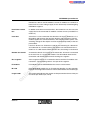
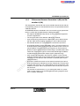
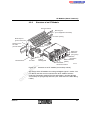
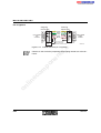
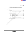
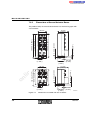
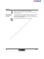
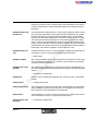
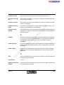
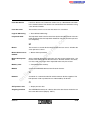
1.3.1
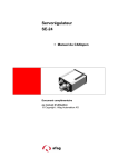
Describing the Bus Components
C o n tr o lle r b o a r d
co
F
F
F
F
IN
B
T E R
IN
U S
B
T E R
IN
U S
T E R
B
U S
nt
s.
U S
B u s te r m in a l
m o d u le
U S
U S
T E R
B
F
F
U S
IN
IN
U S
R e m o te b u s
T E R
B
U S
R e m o te b u s b ra n c h
IN
1
2
3
4
5
6
7
8
9
1 0 1 1 1 2 1 3 1 4 1 5
T E R
B
U S
1 6
B A
R e a d y
R C
U B (1 )
R D
U B (2 )
1
2
3
4
In s ta lla tio n r e m o te b u s
on
l
in
ec
om
po
B
ne
F
T E R
E
IN
L o c a l b u s
E
U S
E
R e m o te b u s
B
T E R
E
U S
E
U S
E
U S
E
S
U
IN
m
L o c a l b u s
2 4 V s u p p ly
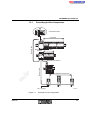
Figure 1-1
6000AC02
6 0 0 0 A 1 0 3
Example of a bus configuration
1-7
IBS SYS PRO INST UM E
Controller board
The controller board takes over the master function in the INTERBUS network. It organizes the data traffic in the INTERBUS system, independent of
the control or computer system in which it is installed.
Controller boards are available for a wide range of control and computer
systems.
Tasks of the controller board:
–
Reading the input data of the modules
–
Monitoring INTERBUS
–
Sending error messages to the host system
–
Indicating diagnostic messages
–
Controlling the cyclic I/O protocol
nt
s.
co
m
Transmitting output data to the output modules
The first step in setting up a modular I/O station is to connect the BK module to the INTERBUS remote bus cable. I/O modules may be installed
branching off from these BK modules, to create a local bus.
ne
Bus terminal module
(BK module)
–
po
A BK module divides the system into segments, thus allowing you to switch
off single branches during operation. In addition, the BK module supplies
communications power to the connected I/O modules.
in
ec
om
A BK module must be supplied with non-interruptible voltage. This means
that the voltage may not be off at the same time as the subsystem if the
whole bus system is to continue operation. A breakdown of the supply voltage on the BK module stops the system and causes an error message for
the bus segment.
on
l
Tasks of the BK module:
Remote bus
1-8
–
Coupling of the remote bus and local bus
–
Supplying the I/O modules with communications power
–
Updating the data signal (repeater function)
–
Electrical isolation of the bus segments
–
Connecting or disconnecting the local bus via firmware (disconnecting
via hardware is only possible if fiber optic interfaces are used). The outgoing remote bus can be disconnected for Generation 4 or later.
–
Error message via an electrically isolated alarm output (e.g., sound signal, light signal)
The remote bus cable connects the controller board with the remote bus
devices and the remote bus devices with each other.
6000AC02
INTERBUS System Basics
Remote bus devices are BK modules, certain I/O modules or a mixture of
both. Each has a local voltage supply and an electrically isolated outgoing
INTERBUS segment.
In addition to the data transmission lines, the remote bus can also carry the
supply line for the connected I/O modules and the sensors (installation remote bus).
Local bus
A local bus is a bus connection that branches off from a remote bus via a
BK module and connects the local bus devices with each other. The BK
module supplies the connected devices with communications power. The
switching voltage for the outputs must be connected separately to the output modules.
s.
co
m
Installation remote
bus
nt
Local bus devices are I/O devices used for the structuring of a decentralized substation in a control cabinet. The devices are connected to the remote bus via a BK module. Within the local bus, branching is not allowed.
A remote bus branch is a branch off the remote bus. A branch is connected
to the main line via a special BK module. This BK module allows for the
connection and disconnection of the branching bus segment.
Bus segment
A bus segment consists of a remote bus device and the I/O modules connected to it. The preceding cable is also part of the segment.
I/O module
I/O modules connect INTERBUS to the sensors and actuators.
ID code
Each INTERBUS module has an ID code that identifies it to the controller
board or the configuration software. The ID code indicates the module type.
po
om
in
ec
The length code indicates the number and representation format of the process data (bit, nibble, byte, word).
on
l
Length code
ne
Remote bus branch
6000AC02
1-9
IBS SYS PRO INST UM E
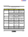
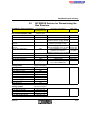
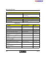
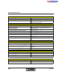
1.3.2
INTERBUS System Data
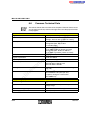
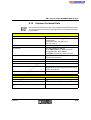
Table 1-1
System data
System
4096, maximum
Number of data words
256, maximum
Transmission speed
500 kbits/s
Transmission reliability
CR check
(Hamming distance: 4)
Protocol
DIN EN 50254
co
s.
Number of Devices
po
12.8 km (7.954 mi.), maximum (copper)
From the controller
board to the first device
400 m (1312.336 ft.), maximum (copper)
om
From the controller
board to the last remote
bus device
in
ec
on
l
254, maximum
ne
Number of remote bus
devices
512, maximum
nt
Total number of bus devices
Distances
m
Number of I/O points
Between two remote bus
devices
80 km (49.710 mi.), maximum (glass fiber)
50 m (164.042 ft.), maximum (polymer fiber)
300 m (984.252 ft.), maximum (HCS fiber)
3000 m (9842.520 ft.), maximum (glass fiber)
400 m (1312.336 ft.), maximum (copper)
50 m (164.042 ft.), maximum (polymer fiber)
300 m (984.252 ft.), maximum (HCS fiber)
3000 m (9842.520 ft.), maximum (glass fiber)
1-10
Between two installation
remote bus devices
50 m (164.042 ft.), maximum (copper)
Between BK module and
installation remote bus
device
50 m (164.042 ft.), maximum (copper)
6000AC02
INTERBUS System Basics
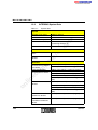
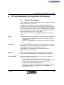
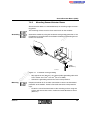
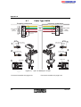
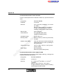
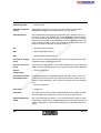
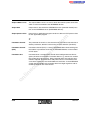
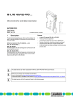
Dimensioning the Remote Bus
The remote bus covers large distances within a system. The entire remote
bus can have a length of 12.8 km (7.954 mi.) (up to 80 km [49.710 mi.] with
glass fiber cable), measured from the controller board up to the last remote
bus module connected. The remote bus can be divided into up to
254 segments.
ne
om
po
m a x . 4 0 0 m
(1 3 1 2 .3 3 6 ft.)
nt
s.
co
m
One bus segment consists of a BK module, or remote bus interface device
and the remote bus cable connected to its remote bus IN connector. With
copper cables the remote bus can cover a distance of 400 m (1312.336 ft.).
in
ec
m a x . 1 2 .8 k m
( 7 .9 5 4 m i.)
on
l
m a x . 4 0 0 m
(1 3 1 2 .3 3 6 ft.)
6 0 0 0 A 1 0 1
Figure 1-2
6000AC02
Maximum cable lengths in the remote bus (copper cable)
1-11
IBS SYS PRO INST UM E
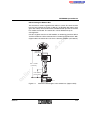
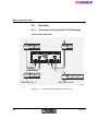
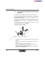
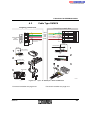
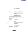
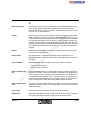
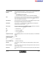
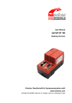
Dimensioning the Installation Remote Bus (IRB)
Certain product families (sensor/actuator boxes, motor starters) allow connection to the remote bus with a hybrid cable, called installation remote
bus. Installation remote bus cables carry communications/sensor power
and data to I/O devices.
m
When using IRB cable, the distance between the BK module and the last
I/O device must not exceed 50 m (164.042 ft.).
In s ta lla tio n r e m o te b u s
5 0 m
co
m a x im u m
po
ne
nt
s.
R e m o te b u s
6 0 0 0 A 1 0 2
om
2 4 V s u p p ly
Figure 1-3
Maximum cable lengths in the installation remote bus
on
l
in
ec
The number of I/O devices in the installation remote bus is limited by the
current consumption of the devices and the connected sensors (see „INTERBUS Devices for Dimensioning the Bus Structure“ auf Seite 3-11). The
total current consumption of these components must not exceed 4.5 A. The
current consumption of the actuators is not added to the calculation, as the
actuators are supplied with a separate I/O voltage.
1-12
6000AC02
INTERBUS System Basics
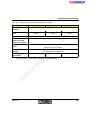
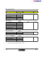
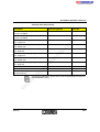
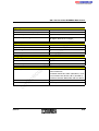
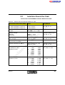
Overview of the Dimensioning of Subsections
Table 1-2
INTERBUS subsections for copper cable
Remote Bus
Installation Remote Bus
Local Bus
Maximum total current consumption
–
4.5 A
0.8 A
ST devices must be directly
mounted side by side.
nt
s.
Between two remote bus devices Between two installation re400 m (1312.336 ft.)
mote bus devices
50 m (164.042 ft.)
–
co
Between controller board and first Between BK module and first
remote bus device
installation remote bus device
400 m (1312.336 ft.)
50 m (164.042 ft.)
m
Maximum cable lengths (copper cable)
po
Maximum number of devices
254
254
om
(Limited by the total current
consumption of the sensors)
in
ec
–
ne
Between controller board and last Between BK module and last
remote bus device
I/O device
12.8 km (7.954 mi.)
50 m (164.042 ft.)
8
(4 if IBS ST 24 BKM-T modules are used)
(Limited by the total current
consumption of the
ST devices)
Bus connection
SAB connector hood
ST cable (local bus)
on
l
9-pos. D-SUB
screw-clamp terminal blocks
(MINI-COMBICON)
6000AC02
1-13
IBS SYS PRO INST UM E
1.3.3
Transmission Medium
The standard transmission type is using twisted-pair cables, but INTERBUS can also use other media such as fiber optics, slip rings and infrared
transmission paths. That means that INTERBUS can also reach parts of
the system that cannot be accessed with copper cables.
Standard interface. Up to 400 m (1312.336 ft.) can be covered between two
stations.
m
Copper cable
Indoor installation
–
Flexible applications (e.g., moving, flexible cable track)
–
Underground installation
nt
s.
–
There are three different types of fiber optics:
–
Polymer fiber cables are easier to assemble than the below mentioned
fiber optics: With polymer fibers approx. 50 m (164.042 ft.) between two
remote bus devices can be covered. (For exact distances see the "Optical Fiber Installation Guidelines", Designation
DB GB IBS SYS FOC ASSEMBLY, Part No. 94 23 43 9.)
–
HCS cable is a hybrid fiber with glass fiber core and plastic fiber sheathing. The assembly is complicated and up to 300 m (984.252 ft.) between two remote bus devices can be covered. (For exact distances
see the "Optical Fiber Installation Guidelines", Designation
DB GB IBS SYS FOC ASSEMBLY, Part No. 94 23 43 9.)
in
ec
om
po
ne
Fiber optics
co
Standard cables are available for:
–
on
l
Slip rings
Infrared transmission paths
1-14
Glass fiber assembly is very complicated. With polymer fibers approx.
3000 m (9842.520 ft.) between two remote bus devices can be covered.
Slip rings allow data transmission to rotating parts.
Infrared transmission paths are used instead of a trailing cable. Infrared
transmission modules convert INTERBUS data signals to infrared light.
These modules transmit and receive data up to 200 m (656.168 ft.) and eliminate the need for an interconnecting cable.
6000AC02
INTERBUS System Basics
1.3.4
Data Transmission Method
The INTERBUS system uses serial data transmission.
For the controller board, all sensors and actuators, including their data, are
grouped together as one "logical" device. The frame data, like start and end
ID, is only sent once per cycle for each device. That means that the more
I/O devices that are connected, the more the user data / frame data ratio
improves. This transmission method is called summation frame protocol.
Shift register
Each INTERBUS device has internal shift registers through which data is
transferred. In each bus cycle the new data pushes the old data by one register so that each bus device sends and receives data within a bus cycle.
If the controller board "knows" which devices are connected to the bus, the
controller board can assign the I/O data to the single devices. Therefore,
each device has a device code indicating the module type and the data
length.
ne
nt
s.
co
m
Summation frame
protocol
INTERBUS devices have two different types of shift registers: identification
registers and data registers.
The identification cycle is run to start up the system and localize errors. The
controller board needs this cycle to identify the devices in the INTERBUS
system. Each device places its ID code in the ring.
om
Identification cycle
(ID cycle)
po
This leads to two different cycle types in the system:
on
l
Data cycle
in
ec
The ID register is not part of the register length calculation. The register
length by means of which an INTERBUS device is connected to the data
ring only depends on the length of its data register.
The second cycle type is the data cycle. This cycle is always run when data
is transmitted.
At the start of the cycle, the controller board generates the loop-back word.
The controller board clocks and pushes the first bit of the loop-back word
from the controller board to the first device. The first device pushes its last
bit (less significant) to the next device. This device pushes its less significant bit to the next device, etc. This simultaneous sending and receiving of
data is called full duplex operation.
The controller board keeps clocking until the loop-back word has returned.
6000AC02
1-15
IBS SYS PRO INST UM E
After the transmission of the user data, an end ID is transmitted for data security, the CRC sequence. Each device checks the CRC before it accepts
data from the IN register to the OUT register. If a CRC error is detected the
output data is not accepted and only the I/O data is read. This method
ensures that new data is available to all devices at the same time. This is
also valid for the controller board. Within the data cycle, all devices have
received new output data and the controller board has received new input
data from the devices.
m
CR check
Transmission of Process and Parameter Data
nt
s.
co
Different input/output devices are used in the field of sensors/actuators.
Among these devices are those processing only very little information like
valves or switches. Information from such devices is process data transmitting status information such as switch positions. The transmission of such
data must be quick and cyclical.
po
ne
Intelligent devices like frequency inverters or controllers exchange process
data with each other and they also exchange large data amounts with the
control system. Such data can, for example, be needed for the startup
phase of a machine. This parameter data rarely changes and is only transmitted if required.
om
The INTERBUS protocol can transmit simple input/output data (process
data) and complex data records (parameter data) at the same time. For
this, the complex parameter data is divided into small units, transmitted and
put together again.
on
l
in
ec
In the INTERBUS system the Peripherals Communication Protocol (PCP)
divides the parameter data into single segments. After the transmission it
recombines the data. PCP designates the protocol software. This software
makes connection establishment and connection abort possible.
1-16
For detailed information on PCP communication refer to the
IBS SYS PCP G4 UM E User Manual, Order No. 27 45 16 9.
6000AC02
INTERBUS System Basics
1.3.5
Differences Between Generation 3 (G3) and Generation 4 (G4)
The designations G3 and G4 refer to the controller board version with the
corresponding software. A G3 controller board can be parameterized with
CMD G3 software.
m
All INTERBUS devices described in this user manual can be operated on
the bus system with controller boards of both generations.
co
– G4 supports INTERBUS Loop devices and has improved diagnostics
for each single device.
– The two generations have different addressing methods.
s.
– Only the branching interface on the BK module can be disconnected
with G3. With G4 the outgoing interface can also be disconnected.
nt
– G4 controller boards can synchronize bus and control cycle times.
om
po
ne
– As of G4 the control system is offloaded in such a way that the data can
be output directly without running through the control system. There are
two possibilities. The (time-critical) input signals can be transferred
directly to output signals without the link through a condition (direct link).
These time-critical input signals can be linked with/through conditions
and then directly transferred to output signals (preprocessing).
on
l
in
ec
– PCP version 2.0 integrated in G4 firmware supports a PCP channel
width of 1, 2 and 4 words and has better immunity to interference. Communication of PCP devices with each other is possible (peer-to-peer
communications).
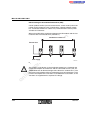
6000AC02
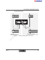
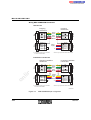
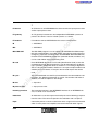
– As of G4 a remote bus branch can be further branched. Up to 16 bus
levels (branching) are allowed (see section "Remote bus structure with
16 levels (G4)" on page 1-18). A BK module can be connected to a BK
module as a branch. This is not possible in G3. The local bus is part of
the next level.
The creation of sub-branches, e.g., for routing the cable in a system
(with no return cable) or for connecting/disconnecting single bus branches is another advantage.
1-17
I/O
I/O
I/O
I/O
nt
B K
s.
co
m
IBS SYS PRO INST UM E
I/O
po
B K
ne
B K
I/O
I/O
I/O
I/O
on
l
in
ec
om
B K
B K
L e v e l 0
B K
I/O
B K
I/O
I/O
I/O
L e v e l 1
L e v e l 2
L e v e l 3
L e v e l 1 5
6 0 0 1 A 0 0 1
Figure 1-4
1-18
Remote bus structure with 16 levels (G4)
6000AC02
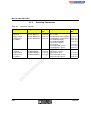
INTERBUS System Basics
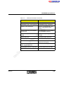
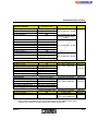
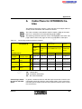
Table 1-3
Differences between G3 and G4
Generation 4
2 device levels
16 device levels
INTERBUS Loop is not supported
INTERBUS Loop is supported
Optional: One-line display
Optional: Four-line display (text
display, more effective diagnostics)
Limited addressing of the INTERBUS devices
Extended addressing possibilities
of the INTERBUS devices
s.
co
m
Generation 3
Synchronous operating modes
possible
Simple direct link
Extended, flexible direct link
ne
nt
Synchronous operation is not supported
Extended, flexible preprocessing
Static RAM board
Parameterization memory (can be
deleted and changed)
po
Simple preprocessing
4-bit devices are supported
Firmware download is not possible
Firmware download is possible
in
ec
om
Devices with a data width below
8 bits are not supported
PCP version 2.0
on
l
PCP version 1.5
6000AC02
1-19
IBS SYS PRO INST UM E
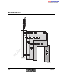
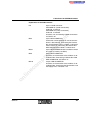
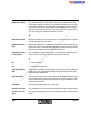
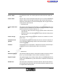
1.4
Overview of the Product Families
1
3
s.
co
m
2
5
on
l
in
ec
om
po
ne
nt
4
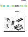
1-20
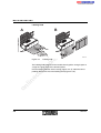
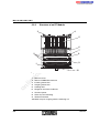
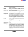
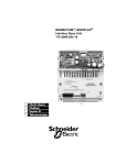
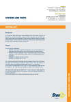
Figure 1-5
6 0 0 0 A 1 0 4
Overview of the INTERBUS modules
1
ST module (Smart Terminal)
2
RT module (Remote Terminal)
3
SAB module (Sensor/Actuator Box)
4
CT-I/O gateway (Configurable Terminal)
5
500 V version of the INTERBUS motor starter
6000AC02
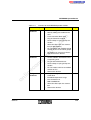
INTERBUS System Basics
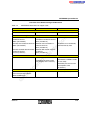
Overview of the INTERBUS product families
in
ec
on
l
6000AC02
–
Modular design
–
Directly adding one module to the
next
–
Passive terminal block base
–
Plug-in electronics module
–
Screw-clamp or spring-clamp connection
–
Alternative fiber-optic bus connection (for BK modules)
–
For I/O stations with medium to high
number of I/Os or functional groups
–
BK module can connect or disconnect the local bus devices
–
Flat housing types for installation in
control cabinets, distribution boxes
or operating units
po
RT
om
Remote
Terminals
Configurable CT
Terminals
m
4-3
co
ST
Page
s.
Smart
Terminals
Features
nt
Product Family
ne
Table 1-4
–
Plug-in terminal block bases
–
Screw-clamp or spring-clamp connection
–
For I/O stations with low to medium
number of I/Os
–
Remote bus devices
–
Flat-pack design for installation in
cable ducts
–
Extended temperature range
–
Bus connection via
MINI-COMBICON
–
Alternative fiber-optic bus connection
–
Remote bus devices
5-3
6-3
1-21
IBS SYS PRO INST UM E
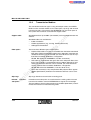
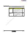
Table 1-4
Overview of the INTERBUS product families
Product Family
Features
Sensor/actu- SAB
ator boxes
–
IP 67 protection
–
5-pos. M12 connector for the connection of sensors/actuators
–
Direct control of actuators possible
through 2 A outputs
–
Remote bus or installation remote
bus devices
–
IP 54
–
Plug-in connection method
–
Power networking (500 V AC)
–
Remote bus or installation remote
bus devices
8-3
nt
s.
co
m
7-3
on
l
in
ec
om
po
ne
500 V version of the
INTERBUS motor
starter
Page
1-22
6000AC02
INTERBUS System Basics
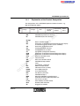
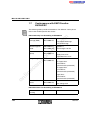
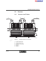
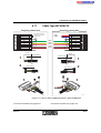
1.4.1
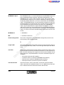
Explanation of the Product Designation
The designations of the INTERBUS products indicate functions, e.g.,
IBS ST 24 BK DIO 8/8/3-T.
D e s ig n
V o lta g e
5 1 0 9 B 1 0 1
s.
ne
nt
Bosch controller board
Generation 4 controller board without diagnostic display
and limited range of functions (basic controller)
Generation 3 controller board
Compact controller housing
Compact PCI bus (32 bits)
CT module (configurable terminal)
Generation 3 controller board with diagnostic display
Generation 4 controller board with diagnostic display
Ethernet controller board
Field Controller
GE Fanuc controller board
INTERBUS Loop module
Inline
IP 67/65/54... protection
Möller controller board
Industrial PCI bus (32 bits)
IP 67 KES protection
IP 67 KIS protection
PC ISA bus (8/16 bits)
INTERBUS Loop 2
Mitsubishi MELSEC controller board
Controller board for IBM-compatible PCs
PC PCI bus (32 bits)
Allen-Bradley controller board
Remote Field Controller
Rugged Line module
po
om
in
ec
on
l
E x te n s io n s
INTERBUS (remote bus devices)
INTERBUS (local bus devices)
Design
BA
BC
6000AC02
C o n n e c tio n
m e th o d
co
IBS
IB
CB
CC
CPCI
CT
DCB
DSC
ETH
FC
GE
IBSL
IL
IP
IPC
IPCI
IPKES
IPKIS
ISA
L2
MEA
PC
PCI
PLC5
RFC
RL
N u m b e r
o f in p u ts /
o u tp u ts
T a s k
m
IB S
IB
1-23
IBS SYS PRO INST UM E
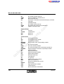
RT
S5/S7
SAB
SC
RT module (remote terminal)
Siemens SIMATIC controller board
Sensor/actuator box
Generation 4 controller board without display (standard
controller)
INTERBUS Loop
ST module (smart terminal)
ST module with spring-clamp connection
VMEbus controller board
s.
nt
Supply Voltage
24
24 V DC
120/230
120/230 V AC
500
500 V AC
400
400 V AC
co
m
SL
ST
ST ZF
VME
on
l
in
ec
om
po
ne
Task/Function
AI
Analog input module
AIO
Analog input/output module
AO
Analog output module
BDO/BDI
Basic version of the corresponding module
BAO/BAI
BK
Bus terminal module
BKM
Basic bus terminal module
CBK
Bus terminal module for the installation remote bus
CDI/CDO
Digital installation remote bus input/output module
CNT
Counter module
DI
Digital input module
DIO
Digital input/output module
DO
Digital output module
ELR
Electronic load relay
FT
Fault-tolerant
GT
I/O gateway
INC
Incremental encoder module
MLR
Mechanical load relay
PT
Resistance temperature sensors
R/RELS
Relay output
SEB
High-speed exciter module
UTH
Thermocouples
V.24
Serial connection V.24/RS-232
1-24
6000AC02
INTERBUS System Basics
VFD
Frequency inverter
WT
Extended temperature range
Number of Inputs/Outputs and/or Connection Method/Slots/Groups
16 inputs with 4 groups
16 inputs on 8 slots
24 inputs, 16 outputs
32 channels, 2-wire technology
Extensions
-2A
-LK
-S
-T
/BP
/ETH
/l
LB/RB
-SF
Current limit
With fiber-optic connection
Special function
With copper remote bus connection (twisted pair)
Bipolar
With Ethernet interface
With electrical isolation
Local bus/remote bus
With special function
on
l
in
ec
om
po
ne
nt
s.
co
m
Examples:
16/4
16/8
24/16
32/2
6000AC02
1-25
IBS SYS PRO INST UM E
1.5
INTERBUS Software
The programs IBS CMD (for standard controller boards) and
IBS PC WORX (for Field Controllers) are available for the configuration
operation and parameterization of your INTERBUS system. With these
programs you can configure, program and visualize all devices integrated
in the INTERBUS system.
co
m
IBS CMD is the INTERBUS-specific user interface for the configuration
operation, monitoring and diagnostics of field devices. Complex functions
are clearly structured and arranged. All devices can be parameterized,
operated and diagnosed from a central location.
s.
IBS CMD is available in different versions for G3 and G4 INTERBUS controller boards.
ne
nt
In addition to IBS CMD functions, PC WORX offers a programming interface according to IEC 61131-3 and optional process visualization.
on
l
in
ec
om
po
PC WORX requires the use of certain G4 controller boards (Field Controllers/Remote Field Controllers). Field Controllers can only be configured
and parameterized with PC WORX. The programs run completely on the
Field Controller so that the host PC is free for operation and visualization
tasks.
1-26
6000AC02
INTERBUS System Basics
1.5.1
IBS CMD (G3 and G4)
Interactive and control-independent configuration, operation and diagnostics of all connected devices in an INTERBUS system is possible with
IBS CMD software.
IBS CMD runs on standard PCs under MS WINDOWS® and can be used
for a number of INTERBUS controller boards.
co
m
The PC is coupled to the controller board through a serial interface
(RS-232).
s.
The IBS CMD program is divided into three program parts. These program
parts can be operated in the following logical sequence:
1. The configuration menu commands in IBS CMD are used to design a
complete bus architecture for a system and to configure all the devices
connected to INTERBUS. For example, you can add new devices or
search for certain devices. Addresses can be assigned to the input/output channels of the bus devices. Single bus segments can be grouped
together. It is also possible to test the bus architecture before startup.
Monitoring
2. All of the connected devices can be monitored and influenced by the
"monitor" program extension. During system operation, the I/O states
of connected devices can be indicated and output states can be changed.
The dialog functions enable a partial startup of the system. For testing
single system parts, the entire bus system and the control system do
not have to be installed.
on
l
Diagnostics
in
ec
om
po
ne
nt
Configuration
6000AC02
3. During startup and servicing, the "diagnostics" operating state helps
you to localize and eliminate error sources in the system. In this way, a
defective bus device can be detected.
During bus operation, you can give qualitative and quantitative statements about the transmission quality of the bus system.
For additional information on the IBS CMD SWT program please refer to
the IBS CMD SWT G3 UM E (Order No. 27 53 95 7) or
IBS CMD SWT G4 UM E (Order No. 27 22 25 0) User Manual.
1-27
IBS SYS PRO INST UM E
1.5.2
PC WORX
PC WORX software allows you to configure, program and diagnose processes.
m
PC WORX runs under MS Windows® version 3.1 and can only be used
with Field Controllers (FC) or Remote Field Controllers (RFC). The host PC
is only used for operation and visualization as the programs run completely
on the Field Controller.
co
The PC is coupled to the Field Controller through an RS-232 interface or
an Ethernet interface.
s.
PC WORX consists of two parts: SYSTEM WORX and PROGRAM WORX.
In addition, visualization software with PC WORX drivers can be installed
on the PC WORX basic package.
The entire INTERBUS system and the connected devices can be configured, parameterized and diagnosed with SYSTEM WORX.
po
SYSTEM WORX
ne
nt
The configuration and programming data (e.g., the user-defined variables)
is available to the other program parts through a common database.
PROGRAM WORX is a programming software based on the IEC 61131
standard. This programming software contains five programming languages:
on
l
in
ec
PROGRAM WORX
om
INTERBUS data is not accessed through addresses but through user-defined variables.
Visualization
–
IL (Instruction List)
–
FBD (Function Block Diagram)
–
LD (Ladder Diagram)
–
ST (Structured Text)
–
SFC (Sequential Function Chart)
You can graphically display the system structure and sequence with visualization software. You can also create a user interface to read and write
data during operation.
Phoenix Contact sells Iconics software.
1-28
6000AC02
INTERBUS System Basics
1.6
INTERBUS Addressing
The process data registered in the INTERBUS system must be clearly assigned to an address position in the memory of a control or computer system. Therefore, address areas in the control system must be assigned to
devices with input/output functions.
m
There are two methods for assigning address areas. These methods differ
in simplicity and flexibility.
co
Addresses can be assigned either automatically (→ automatic addressing)
or by the user, e.g., using CMD software (→ user-defined addressing).
on
l
in
ec
om
po
ne
nt
s.
For additional information on addressing and bit assignment in INTERBUS
for your specific control or computer system, please refer to the data sheet
DB GB IBS SYS ADDRESS Data Sheet, Part No. 90 00 99 0.
6000AC02
1-29
IBS SYS PRO INST UM E
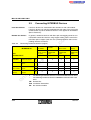
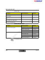
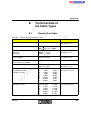
1.7
Conformance with EMC Directive
89/336/EEC
The following tables provide standard data. For different values please
refer to the module-specific data sheets.
EN 61000-4-2/
IEC 61000-4-2
Electromagnetic
fields
EN 61000-4-3
IEC 61000-4-3
Criterion A
Fast transients
(burst)
EN 61000-4-4/
IEC 61000-4-4
Criterion B
s.
6 kV contact discharge
8 kV air discharge
Field strength: 10 V/m
nt
ne
po
om
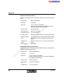
EN 61000-4-5/
IEC 61000-4-5
Supply lines: 2 kV
Signal/data lines: 2 kV
Criterion B
AC supply lines:
2.0 kV/4.0 kV
(symmetrical/asymmetrical)
DC supply lines:
0.5 kV/0.5 kV
(symmetrical/asymmetrical)
in
ec
Conducted interference
Criterion B
co
Electrostatic discharge (ESD)
Surge voltage
on
l
m
Noise Immunity Test According to EN 50082-2
Signal lines:
1.0 kV/2.0 kV
(symmetrical/asymmetrical)
EN 61000-4-6
IEC 61000-4-6
Criterion A
Test voltage 10 V
Noise Emission Test According to EN 50081-2
Noise emission of
housing
1-30
EN 55011
Class A
6000AC02
Section 2
This section informs you about
–
basic connection methods
INTERBUS Installation .........................................................................................2-3
2.1
Note.............................................................................................2-3
2.1.1
Relevant Standards .......................................................2-4
Installation Information ................................................................2-5
2.3
Grounding Concept .....................................................................2-6
2.4
Shielding Concept .......................................................................2-6
2.5
Installing Bus Lines Between Buildings.......................................2-7
2.6
Interference Suppression Measures ...........................................2-9
2.7
Power Supply of Bus Terminal Modules (BK Modules) ............2-10
2.8
Connection of Digital Sensors and Actuators............................2-11
Terms Used .................................................................2-11
2.8.2
Digital Inputs ................................................................2-12
po
2.8.1
2.8.3
Digital Outputs .............................................................2-16
Assembling Standard Connections ...........................................2-19
om
2.9
ne
nt
s.
co
m
2.2
Tools ............................................................................2-19
2.9.2
Assembling D-SUB Connectors...................................2-20
2.9.3
Assembling SUBCON Connectors...............................2-23
2.9.4
Assembling M12 Connectors .......................................2-27
on
l
in
ec
2.9.1
6000AC02
2-1
2-2
6000AC02
s.
nt
ne
po
om
in
ec
on
l
co
m
INTERBUS Installation
2
INTERBUS Installation
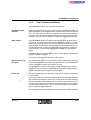
2.1
Note
m
When preparing cable installation, the local conditions and the corresponding mounting regulations are very important. Cables can for example be
installed in cable ducts or cable bridges.
nt
s.
co
A minimum distance between the cabling and possible sources of interference (e. g., machines, welding equipment, power cables) is defined in relevant regulations and standards. During planning and installation of the
INTERBUS system these regulations and standards must be taken into account and observed.
ne
Protect the bus lines from electric/magnetic interferences and mechanical
strain.
Mechanical strain
po
Note the following guidelines for "Electromagnetic Compatibility" (EMC).
To keep mechanical danger low, follow these guidelines:
om
– Choose the correct cable type for each application (e.g., for indoor and
outdoor installation, trailing chains), see "Technical Data of
the Cable Types" on page B-1.
in
ec
– Make sure the bending radius does not fall below a certain value, see
"Technical Data of the Cable Types" on page B-1.
– Cables must not enter the shear area of moving machine parts.
on
l
– Do not install bus lines at right angles to driving paths and machine movements.
Interference
– Use cable ducts or cable bridges.
– Signal and power supply lines should not be installed in parallel. If necessary, metal isolating segments should be placed between the power
supply and signal lines.
– Only use connectors with metal housings and connect as much of the
shielding as possible to the housing.
– Refer to "Installing Bus Lines Between Buildings" on page 2-7 when
grounding cables run between buildings.
6000AC02
2-3
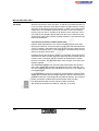
IBS SYS PRO INST UM E
–
Routing of buses in
control cabinets
For the installation, all interlocks of the connectors (screws, cap nuts)
must be firmly tightened to guarantee the best contact between shielding and ground. Before initial startup, the connection between ground
and shielding must be checked for low-resistance continuity.
– Install bus lines in separate cable ducts or separate cable bundles.
– Avoid the installation of bus lines parallel to power supply lines.
– If possible, use metal cable hangers.
co
Routing of buses in
buildings
m
– Install bus lines with a minimum distance of 10 cm (3.937 in.) to power
cables.
– Do not install bus lines together with or parallel to power supply lines.
s.
– Separate bus lines on cable bridges or in cable ducts with isolating segments from the power supply lines.
nt
– Install bus lines as far away as possible from interference sources, for
example, motors and welding equipment.
Routing of buses
outside buildings
po
ne
– For long line connections, install an additional equipotential bonding line
between the connection points.
– Install the bus lines in metal pipes that are grounded on both sides or in
concrete cable ducts with continuous reinforcement.
om
– For long line connections, install an additional equipotential bonding line
between the connection points.
in
ec
2.1.1
Relevant Standards
For grounding, please observe the following standards and regulations.
on
l
– DIN VDE 0100
2-4
– DIN VDE 0185
Please also note "Relevant Standards" on page 1-5.
6000AC02
INTERBUS Installation
2.2
Installation Information
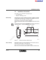
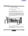
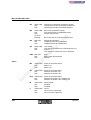
The modules can be mounted in two different ways:
on a mounting rail
–
directly on a mounting surface
Information in this manual regarding rail mounting is based on standardized (EN 50022) mounting rails. The modules are snapped on grounded
mounting rails with clamp angles and spring clamps.
co
m
Rail mounting
–
s.
Rail mounting is possible for the following modules:
Remote Terminals (RT), Smart Terminals (ST) and Configurable Terminals
(CT).
nt
In the Phoenix Contact Catalog the different types of rails are listed with the
designation NS 35... and the corresponding order numbers.
(0 .9 8 4 ")
(0 .2 4 4 ")
2 5 m m
6 .2 m m
om
(1 .3 7 8 ")
3 5 m m
in
ec
on
l
Direct mounting
1 5 m m
(0 .5 9 1 ")
1 0 m m
(0 .3 9 4 ")
po
ne
1 m m
(0 .0 3 9 ")
7 .5 m m
(0 .2 9 5 ")
Figure 2-1
6 0 0 0 A 2 0 1
Standard mounting rail NS 35/7,5CU
When direct mounting is used, the modules are fastened with screws to
grounded mounting angles or mounting plates.
Direct mounting is possible for the following modules:
Motor starter, sensor/actuator boxes (SAB) and Remote Terminals (RT).
6000AC02
2-5
IBS SYS PRO INST UM E
2.3
Grounding Concept
Grounding protects human beings and machines from dangerous voltages.
To avoid these dangers, a correct installation, taking the local conditions
into account, is vital.
m
All INTERBUS devices must be grounded to avoid possible signal interferences.
co
A wire of at least 2.5 mm2 (14 AWG) must be used for grounding
(spring-clamp terminal 1.5 mm2 (16 AWG). For certain device types, larger
wire cross sections may be necessary.
s.
The grounding method depends on the mounting of the modules.
ne
nt
Before a module is installed on a mounting rail, the mounting rail must be
connected with protective earth ground using grounding terminals. In most
cases the module is connected to protective earth ground using a metal clip
on the rear of the module.
om
po
Other modules are installed on a mounting surface (direct mounting). The
PE connection of the housing can be achieved using a mounting screw on
a grounded mounting surface or an outside grounding connection.
2.4
Shielding Concept
on
l
in
ec
Please note the following:
2-6
–
Ensure a large surface connection of the shield under strain relief or install a shield sleeve.
–
Ensure good contact between connector and module (screw connector
tight).
–
Do not damage or squeeze any wires. Do not strip off the wires too far.
–
Use metal-coated or metal connectors with electrical connection to
strain relief.
–
Ensure a clean wire connection.
–
Avoid cold junctions.
–
Ground the modules.
6000AC02
INTERBUS Installation
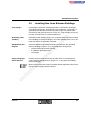
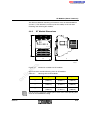
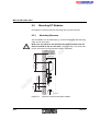
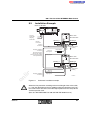
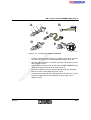
2.5
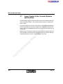
Installing Bus Lines Between Buildings
Overvoltages result from switching operations, electrostatic discharges
and lightning discharges. Overvoltages inject inductively, capacitively or
galvanically into the electrical lines for power supply, measured value
transmission and data transmission. In this way, surge voltages reach supply units and interfaces of systems and devices.
Grounding cable
shielding
Ground the cable shielding (Figure 2-2; 2) directly after it has been installed
in the building to avoid overvoltages. The cable shielding must have a diameter that meets all applicable standards.
Equipotential bonding line
Install an additional equipotential bonding line between the grounding
points of buildings (Figure 2-2; 3), that preferably is designed as
s.
co
m
Overvoltages
nt
– a metal reinforced concrete channel
Phoenix Contact recommends that all cable wires are connected with
surge voltage protection devices (Figure 2-2; 1) to protect the modules
from overvoltages.
om
Surge voltage protection devices
po
– a metal pipe
ne
– an additional grounding cable
on
l
in
ec
Make sure you follow the national and international regulations when installing the surge voltage protection devices.
6000AC02
2-7
IBS SYS PRO INST UM E
2
3
6 0 0 0 A 2 0 2
Surge voltage protection measures
ne
Figure 2-2
nt
s.
co
m
1
Surge voltage protection devices
2
Cable shielding
3
Equipotential bonding line
on
l
in
ec
om
po
1
2-8
6000AC02
INTERBUS Installation
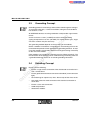
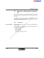
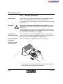
2.6
Interference Suppression Measures
co
m
Phoenix Contact recommends connecting relay coils and motor coils to an
RC element, to protect the modules from interference. Depending on the
application, the delay time of the relay can be increased by
approximately 1 ms.
Relay coil with RC element
nt
Figure 2-3
s.
5001B301
R = 100 – 200 Ω
on
l
in
ec
om
po
C = 220 – 470 nF
ne
For the sizing of the RC element the following values are recommended:
6000AC02
2-9
IBS SYS PRO INST UM E
2.7
Power Supply of Bus Terminal Modules
(BK Modules)
The BK module supplies communications power to the module electronics
of the connected modules. If this communications power is switched off,
the bus stops.
co
m
The power supply of the sensors and actuators should be installed and protected independently of the power supply of the INTERBUS module electronics. This way INTERBUS continues to run even if some I/O devices are
switched off.
on
l
in
ec
om
po
ne
nt
s.
When using an emergency stop circuit, only the power supply of the actuators should be connected to the emergency stop circuit. Errors can then
be detected with the sensors in the emergency stop state.
2-10
6000AC02
INTERBUS Installation
2.8
Connection of Digital Sensors and Actuators
Most of the digital I/O modules of the INTERBUS product families enable
the connection of sensors and actuators in 1-wire, 2-wire, 3-wire or 4-wire
technology.
The term "n-wire technology" means: "n" wires are connected to the input
or output module.
ne
N-wire technology
Terms Used
nt
2.8.1
s.
co
m
In the following, these connection methods are described in general terms.
The explanation of the connection methods is independent of the terminal
assignment of a specific product family.
po
4-wire technology means for example, that the following signals/cables can
be connected to an input module:
Sensor signal (IN)
–
Sensor supply (UL)
–
Sensor ground (⊥)
–
Grounding or shielding of the sensor
on
l
in
ec
om
–
6000AC02
2-11
IBS SYS PRO INST UM E
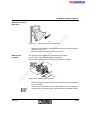
2.8.2
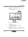
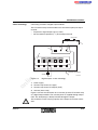
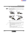
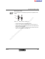
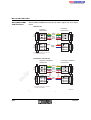
1-wire technology
Digital Inputs
1-wire technology means that the sensor and module are supplied from the
same voltage source. Therefore only one wire is necessary between the
sensor and the module.
The I/O terminal strips of the modules have one terminal point per input
channel:
For the connection of a digital input signal (= IN)
co
m
–
s.
F
2
S
3
in
ec
+ 2 4 V D C
om
po
IN
1
ne
nt
U
+ 2 4 V D C
S
S W
IN
on
l
4
Figure 2-4
6 0 0 0 A 2 0 4
Digital inputs: 1-wire technology
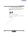
1
Power supply
2
Terminal strip for the I/O supply
3
Terminal strip for the I/O inputs
4
Sensor (here: switch)
Figure 2-4 shows in a schematic way the detection of a sensor signal (4).
The SW switch provides the input signal. The input (IN) indicates "switch
closed/open".
2-12
6000AC02
INTERBUS Installation
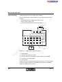
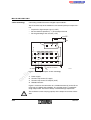
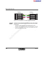
2-wire technology
Connecting 2-wire sensors to digital input modules.
The I/O terminal strips of the modules have one terminal point per input
channel:
– For the connection of a digital input signal (= IN)
– For the sensor supply (UL)
F
U
S
s.
3
1
co
2
S
m
+ 2 4 V D C
ne
nt
4
IN
IN
IN
po
IN
om
U
L
on
l
Figure 2-5
IN
In te r n a l c o n n e c tio n
+ 2 4 V
in
ec
5
6 0 0 0 A 2 0 5
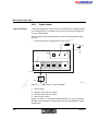
Digital inputs: 2-wire technology
1
Power supply
2
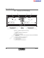
Terminal strip for the I/O supply
3
Terminal strip for I/O inputs (IN) and sensor voltage (UL)
4
I/O inputs of an isolated group
5
2-wire sensor
Figure 2-5 shows the connection of a 2-wire sensor (5). The sensor signal
is led to the input terminal (IN). Sensor power is supplied through the sensor voltage UL.
6000AC02
2-13
IBS SYS PRO INST UM E
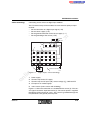
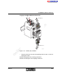
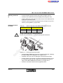
3-wire technology
Connecting 3-wire sensors to digital input modules.
The I/O terminal strips of the modules have one terminal point per input
channel:
– For the connection of a digital input signal (= IN)
– For the sensor supply (= UL)
m
– For the ground connection of the sensor supply (= ⊥)
+ 2 4 V D C
2
U
IN
1
^
s.
ne
IN
S
nt
4
3
S
co
F
IN
IN
IN
po
U
IN
L
om
^
on
l
Figure 2-6
+ 2 4 V
In te r n a l c o n n e c tio n
IN
in
ec
5
5 1 0 9 B 3 1 0
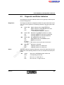
Digital inputs: 3-wire technology
1
Power supply
2
Terminal strip for the I/O supply
3
Terminal strip for I/O inputs (IN), sensor voltage (UL) and GND
4
I/O inputs of an isolated group
5
3-wire sensor
Figure 2-6 shows the connection of a 3-wire sensor (5). The sensor signal
is led to the input terminal (IN). The 3-wire sensor power is supplied through the terminal points UL and ⊥.
2-14
6000AC02
INTERBUS Installation
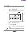
4-wire technology
Connecting 4-wire sensors to digital input modules.
The I/O terminal strips of the modules have one terminal point per input
channel:
– For the connection of a digital input signal (= IN)
– For the sensor supply (= UL)
– For the ground connection of the sensor supply (= ⊥)
m
– For the grounding of the sensor (= FE)
+ 2 4 V D C
2
U
IN
IN
IN
L
F E
om
U
po
ne
IN
nt
4
3
1
s.
S
S
co
F
on
l
Figure 2-7
+ 2 4 V
IN
in
ec
5
In te r n a l c o n n e c tio n
5 1 0 9 B 3 1 1
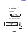
Digital inputs: 4-wire technology
1
Power supply
2
Terminal strip for the I/O supply
3
Terminal strip for I/O inputs (IN), sensor voltage (UL), GND and FE
4
I/O inputs of an isolated group
5
4-wire sensor (3-wire sensor with shielding)
Figure 2-7 shows the connection of a shielded 3-wire sensor (5). The sensor signal is led to the input terminal IN (4). The sensor power is supplied
through the terminal points UL and ⊥. The sensor is grounded through the
FE (functional earth ground) terminal point.
6000AC02
2-15
IBS SYS PRO INST UM E
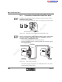
2.8.3
1-wire technology
Digital Outputs
1-wire technology means that the actuator voltage and the supply voltage
have the same reference ground. Therefore, only one wire is necessary
between the actuator and the module.
co
m
The I/O terminal strip of the module has one terminal point per output channel:
– To pick off a digital output signal (= OUT)
S
+ 2 4 V D C
1
s.
F
2
S
⊥
ne
nt
U
po
3
O U T
O U T
O U T
om
O U T
in
ec
4
on
l
Figure 2-8
5 1 0 9 B 3 1 2
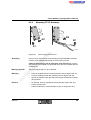
Digital outputs: 1-wire technology
1
Power supply
2
Terminal strip for the I/O supply
3
Terminal strip for the I/O outputs (OUT)
4
Actuator (here: lamp)
Figure 2-8 shows the connection of an actuator (4) to the I/O terminal strip
of a digital output module. The load (lamp) is directly switched through output OUT.
The maximum current carrying capacity of the output must not be exceeded.
2-16
6000AC02
INTERBUS Installation
2-wire technology
Connecting actuators to digital output modules.
The I/O terminal strips of the module have one terminal point per output
channel:
– To pick off a digital output signal (= OUT)
– For the reference potential (= ⊥) of the output channel
m
+ 2 4 V D C
2
1
S
^
s.
U
S
co
F
O U T
O U T
O U T
po
O U T
ne
nt
3
in
ec
om
^
on
l
Figure 2-9
4
In te r n a l c o n n e c tio n
5 1 0 9 B 3 1 3
Digital outputs: 2-wire technology
1
Power supply
2
Terminal strip for the I/O supply
3
Terminal strip for the I/O outputs (OUT)
4
Actuator (here: lamp)
Figure 2-9 shows the connection of an actuator (4) to the I/O terminal strip
of a digital output module. The actuator power is supplied through output
OUT. The load (lamp) is directly switched through the output.
The maximum current carrying capacity of the output must not be exceeded.
6000AC02
2-17
IBS SYS PRO INST UM E
3-wire technology
Connecting shielded actuators to digital output modules.
The I/O terminal strip of the module has one terminal point per output channel:
– To pick off a digital output signal (= OUT)
– For the reference potential (= ⊥) of the output channel
– For the grounding of the actuator (= FE)
2
^
S
1
s.
U
S
co
F
m
+ 2 4 V D C
O U T
O U T
po
^
O U T
ne
O U T
nt
3
OO UU T T
in
ec
4
om
F E
on
l
Figure 2-10
In te r n a l c o n n e c tio n
5 1 0 9 B 3 1 4
Digital outputs: 3-wire technology
1
Power supply
2
Terminal strip for the I/O supply
3
Terminal strip for the I/O outputs (OUT)
4
Shielded actuator
Figure 2-10 shows the connection of a shielded actuator (4) to the I/O terminal strip of a digital output module. The actuator power is supplied through output OUT. The load is directly switched through output OUT.
The maximum current carrying capacity of the output must not be exceeded.
2-18
6000AC02
INTERBUS Installation
2.9
2.9.1
Assembling Standard Connections
Tools
m
The following tools are necessary for cable assembly. For the different connection types not all tools are used, so in the corresponding installation descriptions the necessary tools are mentioned.
– Stripping tool, adjustable
Order Designation KAMES LWL, Order No. 12 06 14 6
co
Copper cable
s.
– Diagonal cutter
Order Designation S 165, Order No. 12 01 91 8
nt
– Cable stripper, adjustable (min. 3 to 6 mm [0.118 in. to 0.236 in.])
Order Designation QUICK-WIREFOX 6, Order No. 12 04 38 4
ne
– Soldering iron or soldering station with flat tip (1.6 mm [0.063 in.]) and
tin-lead solder (LsN 60)
po
– Screwdriver (2.5 mm [0.098 in.])
Order Designation SZF 0 – 0,4 x 2,5, Order No. 12 04 50 4
– Screwdriver (3.5 mm [0.138 in.])
Order Designation SZF 1 – 0,6 x 3,5, Order No. 12 04 51 7
om
– Wrench (17 mm and 21 mm [0.669 in. and 0.827 in.])
– IP 65 assembly wrench,
Order Designation IBS CCO MT, Order No. 27 58 32 1
in
ec
– Crimping pliers
Order Designation HC-ZA 15D, Order No. 17 72 79 3
on
l
– Crimping pliers for ferrules (0.5 to 2.5 mm2 [20 to 14 AWG])
Order Designation CRIMPFOX UD 6, Order No. 12 04 43 6
Optical fiber (polymer fiber)
– Continuity tester
Order Designation PT 1, Order No. 12 02 40 9
– Stripping tool, adjustable
Order Designation KAMES LWL, Order No. 12 06 14 6
– Stripping pliers
Order Designation PSM-FO-STRIP, Order No. 27 61 37 6
– Assembly case for polymer fibers
Order Designation PSM-POF-KONFTOOL, Order No. 27 44 13 1
– Optical fiber measuring device, set
Order Designation PSM-FO-POWERMETER, Order No. 27 99 53 9
6000AC02
2-19
IBS SYS PRO INST UM E
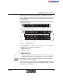
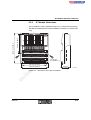
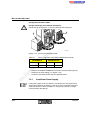
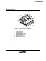
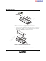
2.9.2
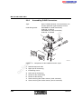
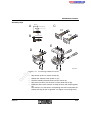
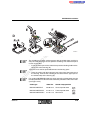
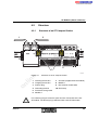
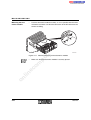
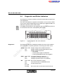
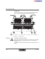
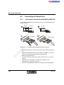
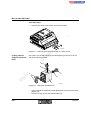
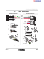
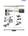
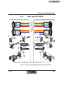
Assembling D-SUB Connectors
9-pos. D-SUB connector, male and female, mechanical protection against polarity reversal
Order Designation:
IBS DSUB 9/L (solder connection),
Order No. 27 58 47 3
IBS DSUB 9/C (crimp connection),
Order No. 27 58 48 6
m
Type:
3
s.
co
2
ne
nt
1
in
ec
po
om
8
on
l
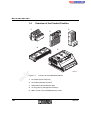
Figure 2-11
2-20
4
5
6
7
6 0 0 0 A 2 1 1
Components of the D-SUB connector, 9-pos.
1
Shield clamp/strain relief
2
Upper part of the housing
3
Interlocking screws
4
Lower part of the housing
5
Screws for the shield clamp
6
Screws for the housing
7
Contact housing with solder contacts (male connector)
8
Contact housing with solder contacts (female connector)
6000AC02
INTERBUS Installation
Assembly steps
2 0 m m
(0 .7 8 7 ")
A
8 m m
C
(0 .3 1 5 ")
C 1
B
C 2
(0 .1 1 8 " )
s.
nt
E
co
m
3 m m
in
ec
om
po
ne
D
on
l
Figure 2-12
6000AC02
6 0 0 0 A 2 1 2
Assembling D-SUB connectors
•
Strip 20 mm (0.787 in.) off the sheath (A).
•
Shorten the shield to 8 mm (0.315 in.) (A).
•
Fold the shielding uniformly back over the sheath (A).
•
Strip 3 mm (0.118 in.) off the wires. Cut the white wire off (B).
•
Solder the wires to the contacts or crimp the wires with crimping pliers
(C).
The contacts of a connector in crimp design must be inserted into the
contact housing (for pin assignment, see Figure 2-13 on page 2-22).
2-21
IBS SYS PRO INST UM E
As much of the shielding as possible must be in contact with the shield
clamp and the lower part of the housing to ensure optimum shielding. The
shield clamp also causes strain relief.
•
Place the cables with their contact housing in the slot of the lower part
of the housing and connect the shielding of the cable with the shield
clamp of the housing and screw it tight (D).
Screw the shield clamp tight using the two countersunk screws.
Insert the interlocking screws into the drill holes of the contact housing
and place them into the guideways of the lower part of the housing.
Snap the upper part of the housing on the lower part and fasten the
housing pieces together using the two socket-head cap screws (E).
s.
co
•
m
The wires must not be squeezed between the housing parts.
Pin assignment
5
9
6
1
6
2
7
po
9 -p o s . D -S U B
m a le c o n n e c to r
D O
D I
D I
C O M
1
Y e llo w
G re e n
G ra y
P in k
B ro w n
ne
D O
In c o m in g
re m o te b u s
nt
O u tg o in g
re m o te b u s
3
5
om
S o ld e r
s id e
D O
6
D O
D I
D I
7
3 C O M
S tr a in
r e lie f
9
5
2
T h is ju m p e r s h o u ld
o n ly b e c o n n e c te d if
a fu r th e r m o d u le fo llo w s .
1
6
9 -p o s . D -S U B
fe m a le
c o n n e c to r
S o ld e r
s id e
6 0 0 0 A 2 1 3
D-SUB connector pin assignment
in
ec
Figure 2-13
9
S tr a in
r e lie f
1
on
l
The contacts 5 and 9 are only jumpered in the outgoing connector.
2-22
6000AC02
INTERBUS Installation
2.9.3
Assembling SUBCON Connectors
9-pos. D-SUB connector, male and female, mechanical protection against polarity reversal
Order Designation:
SUBCON 9/F-SH (female connector,
screw-clamp connection),
Order No. 27 61 49 9
SUBCON 9/M-SH (male connector,
screw-clamp connection),
Order No. 27 61 50 9
co
m
Type:
5
ne
nt
s.
6
7
po
4
om
3
8
on
l
in
ec
2
6000AC02
Figure 2-14
9
1
6 0 0 0 A 2 1 5
Components of the SUBCON connector, (9-pos.)
1
Lower part of the housing
2
Lower part of the shield clamp/strain relief
3
Upper part of the shield clamp/strain relief
4
Screws for the shield clamp
5
Screw for the housing
6
Upper part of the housing
7
Interlocking screws
8
Contact insert
9
Labeling field
2-23
IBS SYS PRO INST UM E
Assembly steps
1 3 m m
(0 .5 1 " )
B
(0 .2 0 ")
6 0 0 0 B 2 1 6
nt
s.
Assembling SUBCON connectors (1)
Strip 50 mm (1.969 in.) off the sheath (A).
•
Shorten the shield to 10 mm (0.394 in.) (A).
•
Fold the shielding uniformly back over the cable sheath (B).
•
Strip 5 mm (0.197 in.) off the wires. Cut the white wire off (B).
•
Crimp the ferrules onto the stripped off wires. Use only small ferrules
or ferrules without bending protection so that the wires are not damaged.
•
Push the wires into the screw-clamp terminals of the connector and
tighten the connection with a screwdriver (C).
om
po
ne
•
in
ec
on
l
C
co
5 m m
Figure 2-15
Pin assignment
5 0 m m
(1 .9 7 ")
m
A
9 -p o s . D -S U B
m a le c o n n e c to r
O u tg o in g
re m o te b u s
5
9
6
1
In c o m in g
re m o te b u s
1
D O
D I
D I
C O M
6
Y e llo w
G re e n
G ra y
P in k
B ro w n
D O
3
7
2
5
S o ld e r
s id e
Figure 2-16
9
S tr a in
r e lie f
1
D O
6
D O
D I
D I
7
3 C O M
S tr a in
r e lie f
9
5
2
T h is ju m p e r s h o u ld
o n ly b e c o n n e c te d if
a fu r th e r m o d u le fo llo w s .
1
6
9 -p o s . D -S U B
fe m a le
c o n n e c to r
S o ld e r
s id e
6 0 0 0 A 2 1 3
SUBCON connector pin assignment
The contacts 5 and 9 are only jumpered in the outgoing connector.
2-24
6000AC02
INTERBUS Installation
E
F
6 0 0 0 B 2 1 7
Assembling SUBCON connectors (2)
po
Figure 2-17
ne
nt
s.
co
3 m m
(0 .1 2 ")
m
D
Insert the lower part of the shield clamp and the labeling field into the
lower part of the housing (D).
in
ec
•
om
The shielding must have uniform contact with the shield clamp and the lower part of the housing to ensure optimum shielding. The shield clamp also
causes strain relief.
The wires must not be squeezed between the housing parts.
on
l
•
6000AC02
Place the cables with their contact insert in the slot of the lower part of
the housing. Connect the shielding of the cable with the upper part of
the shield clamp of the housing (E).
For standard INTERBUS cables the upper part of the shield clamp must be
turned upside down so that the cable cannot be pulled out of the strain relief
(see Figure 2-25).
Cable type
Order No.
Shield clamp position
IBS RBC METER-T
28 06 28 6
Turned upside down
IBS RBC METER/F-T
27 23 12 3
Turned upside down
IBS RBC METER/E-T
27 23 14 9
Not turned
2-25
IBS SYS PRO INST UM E
Ensure that the shielding projects at least 3 mm (0.118 in.) over the shield
clamp (F).
Only then use the two screws to screw the shield clamp tight.
•
Snap the upper part of the housing on the lower part and secure the
connection by screwing it tight (F).
on
l
in
ec
om
po
ne
nt
s.
co
m
•
2-26
6000AC02
INTERBUS Installation
2.9.4
Assembling M12 Connectors
Type:
M12 connector with mechanical protection
against polarity reversal, mechanical interlock through cap nut, IP 67 protection when the connector is inserted.
Twelve different connector types are available:
co
m
4-pos./5-pos., with straight and angled connector, with knurled plastic or metal head (PG7 or
PG9 gland type) and two-pin-plug (PG 11 gland
type).
SACC-M12MS-5CON-PG7 (5-pos., straight connector, with knurled plastic head, PG7),
Order No. 16 62 25 6
SACC-M12MR-5CON-PG7 (5-pos., angled connector, with knurled plastic head, PG7),
Order No. 16 62 26 9
ne
nt
s.
Order Designation:
om
po
Please refer to the Phoenix Contact Catalog for
further ordering data.
5
4
3
in
ec
2
on
l
1
6000AC02
6 0 0 0 A 2 2 3
Figure 2-18 Components of the M12 connector
1
Contact insert
2
Protective cap
3
Grommet
4
Compression ring
5
Cap nut
2-27
IBS SYS PRO INST UM E
Assembly steps
A
3 0 m m
5 m m
(1 .1 8 1 ")
(0 .1 9 7 ")
C
1
5
3
m
D
2
6 0 0 0 A 2 2 4
nt
Assembling M12 connectors
ne
Figure 2-19
s.
co
B
4
Strip approx. 30 mm (1.181 in.) off the outer cable sheath (A).
•
Strip 5 mm (0.197 in.) off the wires.
•
Fit ferrules at the ends.
•
Push grommet into compression ring. Then push the protective cap (2),
grommet (3), compression ring/grommet onto the prepared cable (B).
•
Push the shrink tube for the functional ground (pin 5) over the corresponding wire.
•
Push the wires into the pins of the contact insert (1) and screw into
place. The shrink tube is thus pushed over the central contact. For the
pin assignment please refer to the corresponding data sheets (C).
•
Push protective cap (2) into the contact insert (1).
•
Push compression ring with the grommet into the protective cap and
screw the cap nut into the protective cap (D).
on
l
in
ec
om
po
•
2-28
6000AC02
Section 3
This section informs you about
–
basic INTERBUS configuration
INTERBUS Project Planning ................................................................................3-3
Bus Cable Selection....................................................................3-5
Remote Bus Cables .......................................................3-6
3.1.2
Installation Remote Bus Cables.....................................3-8
3.1.3
Selecting Connectors...................................................3-10
m
3.1.1
co
3.1
INTERBUS Devices for Dimensioning the Bus Structure .........3-11
3.3
Connecting INTERBUS Devices ...............................................3-14
on
l
in
ec
om
po
ne
nt
s.
3.2
6000AC02
3-1
3-2
6000AC02
s.
nt
ne
po
om
in
ec
on
l
co
m
INTERBUS Project Planning
3
INTERBUS Project Planning
The project planning of an INTERBUS system starts with the number of
process input/output points, possible special functions (counting, V.24
transmission, motor control, etc.) and the degree(s) of protection given by
the ambient conditions.
1. Degree of protection required (e.g., IP 20, IP 65, IP 67)
co
Selection criteria
m
The hierarchy of the following criteria determines the selection of the INTERBUS devices.
ne
nt
s.
2. Product group (local bus or remote bus device). When selecting local
bus devices (e.g., Smart Terminals) keep in mind that for the connection to the remote bus one bus terminal module (BK module) per device
group is needed.
Remote bus devices (e.g., Configurable Terminals, Remote Terminals,
Sensor/Actuator Boxes, motor starters) can be operated without preconnected BK module.
3. Signal type and direction (digital, analog, input and/or output)
po
4. Number and combination of the input and output connections available
Maximum number of devices (see „Overview of the Dimensioning of
Subsections“ auf Seite 1-13)
on
l
in
ec
–
om
In each product group the following criteria must be maintained within a
subsection:
–
Current carrying capacity of the BK module (see „INTERBUS Devices for Dimensioning the Bus Structure“ auf Seite 3-11)
–
Maximum length of the entire section and subsections (see „Overview of the Dimensioning of Subsections“ auf Seite 1-13)
Selecting the Controller Board
Look up the suitable controller board for your control system/computer in
the Phoenix Contact catalog.
Controller boards containing "/l" in their designation are electrically isolated
from the control system/computer.
Selecting/Dimensioning the Process Memory
The necessary memory requirements of the INTERBUS I/O data in the
control system are defined in the data sheet "IBS Teilnehmerliste (device
list)" (Part No. 92 70 53 0).
6000AC02
3-3
IBS SYS PRO INST UM E
Configuring the Application Program
When planning the system you can complete the first steps for configuring
the application program. You can, for example, draw up device lists for
PLCs or plans for the memory assignment and define the variables (bit,
byte and word formats).
on
l
in
ec
om
po
ne
nt
s.
co
m
Use the data sheet "IBS Teilnehmerliste (device list)"
(Part No. 92 70 53 0).
3-4
6000AC02
INTERBUS Project Planning
3.1
Bus Cable Selection
Use only cables from Phoenix Contact or cables with the following technical specifications.
Deviations from the mechanical specifications are permissible for special
applications if the electrical features are maintained.
m
The cables must be connected in such a way that the indicated electrical
data is transmitted correctly.
s.
co
Special attention must be paid to the installation of the shielding. The shielding must be connected in such a way that the cable diameter is not reduced. The wires must be covered with as much of the braided shield as possible.
nt
The wire pairs must be twisted up to the connection contacts.
on
l
in
ec
om
po
ne
Two cables should not be connected with each other as losses can be
caused by reflections at the connection point. The shielding effect could
also deteriorate. This is especially the case if different cable types are connected.
6000AC02
3-5
IBS SYS PRO INST UM E
3.1.1
Table 3-1
Remote Bus Cables
Specifications for remote bus cables*
Order No.
IBS RBC METER/F-T
IBS RBC METER/E-T
28 06 28 6
27 23 12 3
27 23 14 9
For fixed wiring
For highly flexible
applications
For permanent indoor
and outdoor installation (even underground)
co
m
Application
IBS RBC METER-T
3 x 2, twisted-pair,
with common shielding (tinned copper braided shield)
DIN 47100
Pink, gray, yellow, green, white, brown (data lines)
0.22 mm² (24 AWG)
7.2 mm (0.283 in.)
Outer cable sheath
Green (RAL 6017),
flame-retardant
Operating temperature
Fixed
-30°C to +70°C
(-22°F to +158°F)
on
l
in
ec
om
po
Outside diameter
ne
Color coding of the
wires
Cable diameter
Weight
Bending radius
Operating capacity
3-6
0.25 mm² (24 AWG)
0.22 mm² (24 AWG)
8.1 mm (0.319 in.)
9.3 mm (0.366 in.)
Green (RAL 6017),
flame-retardant
halogen-free
Black (RAL 9005),
UV-resistant
Fixed
-30°C to +70°C
(-22°F to +158°F)
Fixed
-30°C to +70°C
(-22°F to +158°F)
Flexible
-5°C to +70°C
(+23°F to +158°F)
7.2 kg/100 m (328 ft.)
7.4 kg/100 m (328 ft.)
9.4 kg/100 m (328 ft.)
Fixed
at least 58 mm
(2.283 in.)
Flexible
at least 122 mm
(4.803 in.)
Fixed
at least 75 mm
(2.953 in.)
60 nF/km at 800 Hz, maximum
Urms = 1500 V
Test voltage
wire-wire
Conductor resistance
Additional reinforced
PVC outer sheath
nt
s.
Structure
186 Ω/km, maximum
(loop)
159.8 Ω/km, maximum
(loop)
186 Ω/km, maximum
(loop)
6000AC02
INTERBUS Project Planning
Table 3-1
Specifications for remote bus cables*
IBS RBC METER-T
IBS RBC METER/F-T
IBS RBC METER/E-T
100 Ω
Surge impedance
At least 150 MΩ/km
Characteristic impedance
120 Ω ±20% at f = 0.064 MHz
Environmental compatibility
Free of substances which would hinder coating with paint or varnish
(according to VW specification)
m
Isolation resistance
(after testing the
dielectric strength)
nt
116
These are typical values at 20°C (68°F) ambient temperature.
on
l
in
ec
om
po
ne
*
117
s.
112
INTERBUS certification number
co
100 Ω ±15% at f > 1 MHz
6000AC02
3-7
IBS SYS PRO INST UM E
3.1.2
Specifications for installation remote bus cables*
Order No.
IBS INBC METER/S
IBS INBC METER/E
27 23 13 6
27 59 87 0
27 23 15 2
For fixed wiring
Partially welding-resistant
For highly flexible
applications
Partially welding-resistant
For permanent indoor
and outdoor installation (even underground)
co
Application
IBS INBC METER
m
Table 3-2
Installation Remote Bus Cables
With additional wires for the power supply
3 x 2, twisted-pair (data), 3 single wires (power),
with common shielding (braided shield consisting of high-grade steel)
nt
s.
Structure
DIN 47100
Pink, gray, yellow, green, white, brown (data)
Blue, red, green/yellow (power)
po
ne
Color coding of the
wires
Additional reinforced
PVC outer sheath
0.25 mm² [24 AWG]
(data)
1.0 mm2 [18 AWG]
(power)
0.22 mm² [24 AWG]
(data)
1.0 mm2 [18 AWG]
(power)
Outside diameter
7.9 mm (0.311 in.)
7.9 mm (0.311 in.)
9.4 mm (0.370 in.)
Outer cable sheath
Green (RAL 6017),
flame-retardant
Green (RAL 6017),
flame-retardant
halogen-free
Black (RAL 9005), UV
resistant
Operating temperature
Fixed
-30°C to +70°C
(-22°F to +158°F)
Fixed
-30°C to +70°C
(-22°F to +158°F)
Fixed
-30°C to +70°C
(-22°F to +158°F)
on
l
in
ec
om
0.22 mm² [24 AWG]
(data)
1.0 mm2 [18 AWG]
(power)
Cable diameter
Flexible
-5°C to +70°C
(+23°F to +158°F)
Weight
8.5 kg/100 m (328 ft.)
9.5 kg/100 m (328 ft.)
12.8 kg/100 m (328 ft.)
Bending radius
Fixed at least 64 mm
(2.520 in.)
Flexible at least
119 mm (4.685 in.)
Fixed at least 76 mm
(2.992 in.)
Operating capacity
3-8
65 nF/km at 800 Hz, maximum
6000AC02
INTERBUS Project Planning
Specifications for installation remote bus cables*
IBS INBC METER
IBS INBC METER/S
Test voltage
wire-wire
IBS INBC METER/E
Urms = 1500 V
Conductor resistance
186 Ω/km, maximum
(loop)
159.8 Ω/km, maximum
(loop)
100 Ω
Surge impedance
186 Ω/km, maximum
(loop)
m
Table 3-2
At least 150 MΩ/km
Characteristic impedance
120 Ω ±20% at f = 0.064 MHz
Environmental compatibility
Free of substances which would hinder coating with paint or varnish
(according to VW specification)
s.
co
Isolation resistance
(after testing the
dielectric strength)
114
113
These are typical values at 20°C (68°F) ambient temperature.
on
l
in
ec
om
*
115
po
INTERBUS certification number
ne
nt
100 Ω ±15% at f > 1 MHz
6000AC02
3-9
IBS SYS PRO INST UM E
3.1.3
Connector selection
Cable Type
Order
No.
Connector
Order
No.
IBS RBC METER-T
28 06 28 6 9-pos. D-SUB:
IBS RBC METER/F-T 27 23 12 3
IBS DSUB 9/L (solder connect.)
IBS RBC METER/E-T 27 23 14 9
IBS DSUB 9/C (crimp connect.)
IBS SUBCON 9/F-SH
IBS SUBCON 9/M-SH
IP 65 circular connector
IBS CCO-R/L
IBS CCO-PSM/L (power)
IBS CCO-PSF/L (power)
27 59 88 3
27 59 90 6
27 80 87 8
ne
27 23 13 6 IP 65 circular connector
27 59 87 0
IBS CCO-R/L (bus)
27 23 15 2
IBS CCO-PSM/L (power)
IBS CCO-PSF/L (power)
27 59 88 3
27 59 90 6
27 80 87 8
on
l
in
ec
om
po
Installation remote bus
Standard
IBS INBC METER
Highly flexible
IBS INBC-METER/S
Underground
IBS INBC METER/E
installation
27 58 47 3
27 58 48 6
27 61 49 9
27 61 50 9
nt
s.
co
Remote bus
Standard
Highly flexible
Underground
installation
Designation
m
Table 3-3
Selecting Connectors
3-10
6000AC02
INTERBUS Project Planning
INTERBUS Devices for Dimensioning the
Bus Structure
ST Modules (Smart Terminals)
Current Output/
Consumption (mA)
IBS ST (ZF) 24 BK DIO 8/8/3-LK
IBS ST (ZF) 24 BK DIO 8/8/3-T
IBS ST (ZF) 24 BK LB-T
500
500
on
l
Analog Outputs
IB ST (ZF) 24 AO 4/BP
IB ST (ZF) 24 AO 4/SF
IB ST (ZF) 24 AO 4/SF4
IB ST (ZF) 24 BAO 8/U
IB ST (ZF) 24 BAO 8/U-8B
6000AC02
ST/ST
ST cable
ST/ST
ST cable
ne
po
Current Consumption†
110
65, max. 100
120
120
140
140
120
120
85
110
in
ec
IB ST (ZF) 24 AI 4/BP
IB ST (ZF) 24 AI 4/I
IB ST (ZF) 24 AI 4/SF
IB ST (ZF) 24 AI 4/SF4
IB ST (ZF) 24 BAI 2/BP
IB ST (ZF) 24 BAI 2/SF
IB ST (ZF) 24 BAI 8/I
IB ST (ZF) 24 BAI 8/U
IB ST (ZF) 24 PT100 4/4
IB ST 24 UTH 8
om
Analog Inputs
800
800
500
500
Fiber optic
Remote bus
Remote bus
nt
800
IBS ST 24 BK-FT-T
IBS ST (ZF) 24 BK-LK
IBS ST (ZF) 24 BK-T
IBS ST (ZF) 24 BKM-LK
IBS ST (ZF) 24 BKM-T
F-SMA/F-SMA
9-pos. D-SUB/9-pos. D-SUB
9-pos. D-SUB/9-pos. D-SUB
Local bus branch: 15-pos. D-SUB
F-SMA/F-SMA
Remote bus branch: F-SMA
F-SMA/F-SMA
Remote bus branch: 9-pos. D-SUB
9-pos. D-SUB/9-pos. D-SUB
Local bus: ST connector
Remote bus branch: 9-pos. D-SUB
(See data sheet)
F-SMA/F-SMA
9-pos. D-SUB/9-pos. D-SUB
F-SMA/F-SMA
8-pos. MINI-COMBICON/
8-pos. MINI-COMBICON
s.
IBS ST (ZF) 24 BK RB-LK DIO
8/8/3-LK
IBS ST (ZF) 24 BK-RB-T DIO
8/8/3-LK
IBS ST (ZF) 24 BK RB-T
Cable Type
co
Current output*
500
500
800
Bus Terminal Modules (BK)
Connection Type IN/OUT
m
3.2
Current consumption†
100, max. 130
100, max. 130
100, max. 130
100, max. 120
100, max. 120
Fiber optic
Fiber optic
Remote bus
Remote bus
ST cable
Fiber optic
Remote bus
Fiber optic
Remote bus
3-11
IBS SYS PRO INST UM E
Digital Outputs
Current
Consumption†
Max. 50
Max. 100
Max. 100
Max. 100
Max. 50
Max. 100
Max. 100
Max. 100
Max. 100
Special Function Modules
on
l
IB ST (ZF) 24 CNT
IB ST (ZF) 24 INC/2
IB ST (ZF) 24 PT100 4/4
IB ST 24 UTH 8
IB ST 24 V.24
*
†
3-12
m
ST cable
po
in
ec
IB ST ASI DIO
IB ST (ZF) 24 DIO 8/8/3-2A
IB ST (ZF) 24 DIO 8/8R/3
ST cable
ST/ST
Current
Consumption†
220
Max. 100
50, max. 100
om
Digital Inputs/Outputs
ST/ST
ne
IB ST (ZF) 24 BDO 8/3
IB ST (ZF) 24 BDO 16/3-250
IB ST (ZF) 24 BDO 16/3-500
IB ST (ZF) 24 BDO 32/2
IB ST (ZF) 24 DO 8/3-2A
IB ST (ZF) 24 DO 16/3
IB ST (ZF) 24 DO 16 R/S
IB ST (ZF) 24 DO 32/2
IB ST (ZF) 120/230 DO 8/3-1A
Cable Type
co
IB ST (ZF) 24 BDI 8/4
IB ST (ZF) 24 BDI 16/4
IB ST (ZF) 24 DI 16/4
IB ST (ZF) 24 DI 32/2
IB ST (ZF) 120 DI 16/3
IB ST (ZF) 230 DI 16/3
Connection Type IN/OUT
s.
Digital Inputs
Current Output/
Consumption (mA)
Current
Consumption†
Max. 50
Max. 100
Max. 100
Max. 100
Max. 100
Max. 100
nt
ST Modules (Smart Terminals)
ST/ST (ASI)
ST/ST
ST cable
ST/ST
ST cable
Current
Consumption†
200
200
85
110
130
Permissible total current consumption of all I/O modules
Typical current consumption from the ST local bus
6000AC02
INTERBUS Project Planning
Typ. 100/max. 150
Typ. 150/max. 280
Max. 280
200
100
100
150
100
100
100
100
40
Typ. 40 at 120 V AC
Typ. 30 at 230 V AC
30
ne
IBS RT 230 DI 16-T
Sensor/Actuator Boxes (SAB) Current Consumption (mA)*
Motor Starters
on
l
IBS IP 500 ELR 2-6A DI 8/4
IBS IP 500 ELR P-6A DI 4/4
IBS IP 500 ELR W-6A DI 4/4
IBS IP 500 ELR WP-6A DI 4/4
IBS IP 500 ELR WS-12A DI 4/4
CT-I/O Gateways
IBS CT 24 IO GT-LK
IBS CT 24 IO GT-T
*
9-pos. D-SUB/9-pos. D-SUB
Remote bus branch: 9-pos.
D-SUB
9-pos. D-SUB/9-pos. D-SUB
9-pos. D-SUB/9-pos. D-SUB
Cable Type
Remote bus/
Installation
remote bus
Current Consumption
Typ. 0.3 A + sensor current
Typ. 0.3 A + sensor current
Typ. 0.3 A + sensor current
Typ. 0.3 A + sensor current
Typ. 0.3 A + sensor current
Connection Type IN/OUT
5-pos. MINI-COMBICON/
5-pos. MINI-COMBICON
Cable Type
Installation
remote bus
Current Consumption (mA)
160
240
Connection Type IN/OUT
F-SMA/F-SMA
10-pos. MINI-COMBICON/
10-pos. MINI-COMBICON
Cable Type
Fiber optic
Remote bus
om
po
Connection Type IN/OUT
5-pos. MINI-COMBICON/
5-pos. MINI-COMBICON
in
ec
IBS SAB 24 DI 4/4
IBS SAB 24 DI 8/8
IBS SAB 24 DI 8/16
IBS SAB 24 DIO 4/4/2
IBS SAB 24 DIO 8/4/4
IBS SAB 24 DO 8/8
Remote bus
9-pos. D-SUB/9-pos. D-SUB
nt
IBS RT 24 DI 16-T
IBS RT 24 DI 32-T
IBS RT 24 DIO 8/8R-T
IBS RT 24 DIO 16/8-2A-T
IBS RT 24 DIO 16/16-T
IBS RT 24 DO 16-T
IBS RT 24 DO 32-T
IBS RT 120 DI 16-T
IBS RT 120/230 DO 16-T
Cable Type
m
IBS RT 24 AI 8-T
IBS RT 24 AIO 4/2-T
IBS RT 24 AO 4-T
IBS RT 24 BK RB-T
Connection Type IN/OUT
co
Current Output/
Consumption (mA)
s.
RT Modules
(Remote Terminals)
100
100
100
100
100
100
Typical current consumption from the installation remote bus (500 mA permissible
current consumption at nominal voltage per module (with load))
6000AC02
3-13
IBS SYS PRO INST UM E
3.3
Connecting INTERBUS Devices
Local bus devices are connected to the remote bus with a BK module.
Local bus devices can only be combined with each other. They cannot be
combined with any other remote bus devices. This applies for ST modules
(Smart Terminals).
Remote bus devices
In general, remote bus devices with fiber optic connection cannot be connected with remote bus devices using copper cables. For the conversion
from fiber optic to copper (and vice versa) Phoenix Contact offers corresponding interface converters.
Connecting remote bus devices (copper)
To
INTERBUS IN
SAB
Motor starter
CT-I/O
gateway
From
D-SUB
MINIfemale connec- COMBICON,
tor, 9-pos.
8-pos.
MINICOMBICON,
5-pos.
MINICOMBICON,
10-pos.
INTERBUS OUT
RB
RB
RB
D-SUB male
connector, 9-pos.
ST-BKM
MINI-COMBICON,
RB
8-pos.
SAB
Motor starter
MINI-COMBICON, RB
5-pos.
IRB
CT-I/O
gateway
MINI-COMBICON,
RB
10-pos.
IRB
nt
x
x
x
–
x
x
x
x
–
x
x
x
x
–
x
–
–
–
x
–
x
x
x
–
x
om
in
ec
on
l
3-14
RB
RB
po
ST-BK
RT module
ST-BKM
ne
ST-BK
RT module
s.
Table 3-4
co
m
Local bus devices
x
–
The following remote bus devices can be connected with each other.
The following remote bus devices cannot be connected with each
other.
RB Remote Bus
IRB Installation Remote Bus
BK Bus terminal module
6000AC02
Section 4
This section informs you about
–
the module overlapping properties of ST modules
ST Modules (Smart Terminals).............................................................................4-3
4.1
Product Description.....................................................................4-3
4.2
Structure......................................................................................4-5
4.2.3
Structure of an ST Module .............................................4-7
co
LEDs on BK Modules...................................................4-10
4.3.2
LEDs on Input/Output Modules....................................4-11
nt
4.3.1
Mounting ST Modules ...............................................................4-12
4.4.1
Mounting Distances .....................................................4-12
4.4.2
ST Module Dimensions................................................4-13
4.4.3
Mounting ST Modules ..................................................4-14
Removing ST Modules.................................................4-17
om
Connecting the Remote Bus .....................................................4-19
Connecting a Remote Bus With a D-SUB Connector ..4-19
4.5.2
Connecting a Remote Bus With MINI-COMBICON .....4-21
4.5.3
Connecting a Remote Bus Using Fiber Optics ............4-24
in
ec
4.5.1
Common Technical Data...........................................................4-25
on
l
4.6
s.
Diagnostic and Status Indicators.................................................4-9
4.4.4
4.5
m
Structure of an ST Bus Terminal Module.......................4-6
ne
4.4
Structure of an ST Compact Station ..............................4-5
4.2.2
po
4.3
4.2.1
6000AC02
4-1
4-2
6000AC02
s.
nt
ne
po
om
in
ec
on
l
co
m
ST Modules (Smart Terminals)
4
ST Modules (Smart Terminals)
4.1
Product Description
ST modules are used for I/O stations with a medium to high I/O number or
functional groups.
m
In most cases the electronics module is pluggable. It can be easily exchanged without having to remove a wire from the terminal block.
nt
s.
co
The ST modules are connected to INTERBUS through a bus terminal module (BK module). An ST compact station is comprised of a BK module and
up to eight I/O modules (see Figure 4-1). The BK module supplies the communications power to the I/O modules. In the bus topology, a compact station is the same as a local bus, as it is connected to the remote bus through
a BK module.
Analog and digital input/output modules are available in the ST family. Special function modules are also available.
ne
Types
om
po
ST family modules can have: (In addition to the listed versions, there are
many modules in a standard version and a version with extended functionality. Almost all modules are available either with screw-clamp or springclamp terminals):
8, 16, or 32 digital inputs each having 24 V DC supply voltage; 16 digital
inputs alternatively with 24 V AC, 120 V AC or 230 V AC supply voltage
–
8, 16, or 32 digital outputs each having 24 V DC supply voltage;
16 digital outputs with 250 mA or 500 mA output current;
8 digital outputs with 120 - 230 V AC supply voltage;
digital output modules with 16 relay N/O contact outputs
–
8 digital inputs and 8 relay contact changeover outputs;
8 digital inputs and 8 digital outputs;
8 digital inputs and 8 digital outputs (with special functions)
–
2, 4, or 8 analog inputs (with special functions)
–
4 or 8 analog outputs (with special functions)
–
Special function modules like counters, positioning modules, V.24
(RS-232) interfaces, ASI link module
–
BK modules with copper fiber-optic connection
–
BK module with 8 digital inputs and 8 digital outputs and with copper or
fiber-optic connection
on
l
in
ec
–
6000AC02
4-3
IBS SYS PRO INST UM E
–
BK module with 8 digital inputs and 8 digital outputs and remote bus
branch and with copper or fiber-optic connection
–
BK module with remote bus or local bus branch
–
BK module with dual bus connection (redundancy)
ST modules (IP 20 protection) are used for applications in closed control
cabinets. Because of their compact design, ST modules can be located in
small control cabinets.
Mounting
ST modules are rail mounted and grounded through the mounting rail.
Bus connection
The remote bus is connected through 9-pos. D-SUB connectors or MINICOMBICON connectors.
s.
co
m
Positioning
nt
Alternatively, BK modules are available with fiber-optic connection.
ne
ST modules are connected with each other through ST cables (local bus
connection).
ST modules have multi-wire terminals to connect 2-, 3- and 4-wire sensors
or actuators. For the connection of the wires the screw-clamp or springclamp method is used.
po
I/O connection
on
l
in
ec
om
When connecting sensors and actuators please note that the terminal numbering of the inputs and outputs does not always correspond to the mapping of the data in the INTERBUS data word.
Each module-specific data sheet shows the assignment of the module terminals to the INTERBUS data word.
4-4
6000AC02
ST Modules (Smart Terminals)
4.2
Structure
4.2.1
Structure of an ST Compact Station
2
IN
U S
T E R
IB S T M E 2 4 D IO
U S
B A
E
1
L D
2
3
4
5
6
7
8
K 1
K 2
nt
C C
B A
C C
K 3
K 4
K 5
K 6
K 7
K 8
ne
8 d ig ita l In p u t , 8 r e la y O u tp u t
2 4 V D C , M o d u le Id e n t.: 1 9 1
9
in
ec
om
8
po
1 0
on
l
Figure 4-1
IN
, O rd . N o .: 2 7 5 1 8 3 6
U s 1
U L
U L
8 /8 R /3
B
T E R
F
F
B
s.
F
F
B
3
E
T E R
U S
E
IN
U S
E
U S
E
U S
co
m
1
4
U S
U s 1
E 1
U s 2
E 2
U L
C C
B A
1
2
3
4
5
6
7
8
6
5
7
5 1 0 9 B 0 0 1
Structure of an ST compact station
1
Incoming remote bus
7
ST cable (supplied with the module)
2
Outgoing remote bus
8
Module 1
3
Dummy plug
9
Bus terminal module (BK)
4
Grounding terminal
10 End clamp
5
Protective earth ground
6
Module 2
Use a dummy plug to isolate the open local bus connection of the last
ST module. The dummy plug is delivered with each ST BK module.
6000AC02
4-5
IBS SYS PRO INST UM E
4.2.2
Structure of an ST Bus Terminal Module
W ir e te r m in a tio n
M o u n tin g r a il
( is n o t s u p p lie d a s s ta n d a r d )
M e ta l c lip s fo r
g r o u n d c o n n e c tio n
co
ne
nt
T R 5 fu s e
s.
R e c e s s fo r th e
S T c a b le
( o n b o th s id e s )
m
S c r e w o p e n in g
om
po
T e r m in a l
b lo c k
O u tg o in g
re m o te b u s
In c o m in g
re m o te b u s
D ia g n o s tic
in d ic a to r s
in
ec
F o ld in g
la b e lin g fie ld
on
l
Figure 4-2
R e m o v a b le
e le c tr o n ic s m o d u le
M o d u le d e s c r ip tio n
6 0 0 0 A 4 0 2
Structure of an ST BK module
The ST BK module connects the ST modules with the remote bus. It supplies the bus logic of the connected INTERBUS ST modules with communications power through the ST cable.
The number of ST modules that can be connected on a specific local bus
depends on the current consumption of the modules (see „INTERBUS Devices for Dimensioning the Bus Structure“ auf Seite 3-11).
The ST BK module is also available with fiber-optic connection.
BK modules are available with additional interfaces and/or I/O connections.
Certain BK modules allow the creation of a remote bus branch
(IBS ST 24 BK-RB-T) or a local bus branch (IBS ST 24 BK-LB-T).
4-6
6000AC02
ST Modules (Smart Terminals)
4.2.3
Structure of an ST Module
W ir e te r m in a tio n
M o u n tin g r a il
( is n o t s u p p lie d a s s ta n d a r d )
R e c e s s fo r th e
S T c a b le
( o n b o th s id e s )
S T c a b le
F o ld in g
la b e lin g fie ld
om
T e r m in a l b lo c k
po
ne
nt
T R 5 fu s e
H o r iz o n ta l
g ro o v e
s.
M e ta l c lip s fo r
g r o u n d c o n n e c tio n
co
m
S c r e w o p e n in g
on
l
in
ec
Figure 4-3
6000AC02
D ia g n o s tic
in d ic a to r s
(re d , g re e n )
M o d u le
d e s c r ip tio n
S ta tu s in d ic a to r s
( y e llo w )
R e m o v a b le
e le c tr o n ic s m o d u le
6 0 0 0 A 4 0 3
Structure of an ST module (screw-clamp variant)
The design of the ST modules for analog and digital signals is similar. You
can directly wire the sensors and actuators to ST modules with the
multi-wire connection method. The wire termination is possible through
screw-clamp or spring-clamp terminals ("ZF" extension in the order designation).
4-7
IBS SYS PRO INST UM E
Labeling Field
A
B
S E
F U
S E
F U
S E
F U
S E
F U
S E
F U
m
S E
F U
S E
F U
Labeling field
po
Figure 4-4
6 0 0 0 A 4 0 4
ne
nt
s.
co
S E
F U
om
The labeling field integrated in the module housing offers enough space to
assign the signal name to the terminal points.
on
l
in
ec
Pull the labeling field out of the housing (Figure 4-4; A), label the corresponding field and re-insert the labeling field (Figure 4-4; B).
4-8
6000AC02
ST Modules (Smart Terminals)
4.3
Diagnostic and Status Indicators
For quick local error diagnostics, the modules have diagnostic and status
indicators.
The diagnostic indicators (red/green) indicate the type and location of the
error. The module is functioning correctly if all of the green LEDs are on.
Status
The status indicators (yellow) indicate the status of the corresponding input
or output.
co
m
Diagnostics
s.
The LEDs listed below are typical for INTERBUS modules, but not all of the
LEDs are on every module. Depending on the module type, additional indicators can also indicate the status of the module.
ne
nt
For additional information about a certain module please refer to the corresponding data sheet.
INTERBUS
E
LD RD
INTERBUS
Us1
E1
2
3
IB ST 24 DI 16/4
Us2
E2
6
7
Us3
E3
10
11
Us4
E4
UL
CC
BA
1
4
5
8
9
12
13
14 15 16
Module Ident.: 190
in
ec
om
UL RC BA
po
IBS ST 24 BK-T
5109B004
Typical diagnostic and status indicators
on
l
Figure 4-5
Bus Terminal, 24 V DC, Module Ident.: 08
6000AC02
4-9
IBS SYS PRO INST UM E
4.3.1
LEDs on BK Modules
Depending on the type of BK module, the following states can be read:
Diagnostics
Green LED Supply voltage of the electronics module
ON:
Supply voltage in permissible tolerance zone
OFF:
Supply voltage not present
– Fuse blown
– Internal power supply unit defective
RC
Green LED Remote bus connection (remote bus check)
ON:
Incoming remote bus connection established
OFF:
Incoming remote bus connection defective
BA
Green LED
ON:
OFF:
As of G4
Flashing:
nt
ne
po
RD
on
l
Bus active, but no cyclic data transmission
Local bus error
Error
No error
Red LED
ON:
OFF:
Local bus disabled
Local bus switched off
Local bus switched on
Red LED
ON:
OFF:
Remote bus disabled
Outgoing remote bus switched off
Outgoing remote bus switched on
in
ec
LD
4-10
Bus active (remote bus active)
Data transmission on INTERBUS active
No data transmission
Red LED
ON:
OFF:
om
E
Status
s.
co
m
UL
If BK modules have an input/output function, the status of the corresponding input/output can be read.
XX
Yellow LED Status input/output
ON:
Corresponding input/output is set
OFF:
Corresponding input/output is not set
6000AC02
ST Modules (Smart Terminals)
4.3.2
LEDs on Input/Output Modules
Diagnostics
Green LED
ON:
OFF:
I/O supply voltage
Supply voltage in permissible tolerance zone
Supply voltage not present
UL
Green LED
ON:
OFF:
Supply voltage of the electronics module
Supply voltage in permissible tolerance zone
Supply voltage not present
– Incoming ST cable not plugged in
– Fuse blown in BK module
– Internal power supply unit of the BK module
defective
CC
Green LED
ON:
OFF:
Incoming ST cable connection
ST cable connection established
ST cable connection defective
BA
Green LED
ON:
OFF:
As of G4
Flashing:
ne
nt
s.
co
m
US
om
po
Bus active (remote bus active)
Remote bus active
Remote bus not active
in
ec
E(n) Red LED
ON:
Status
on
l
OFF:
LEDs on PCP modules
6000AC02
Bus active, but no cyclic data transmission
Error of a certain group
– Short circuit or overload of an output of the
group (n)
– Short circuit or overload of the sensor supply of a
group (n)
– No error
The status of the input/output can be read on the corresponding yellow
LED:
XX
Yellow LED
ON:
OFF:
Status input/output
Corresponding input/output is set
Corresponding input/output is not set
In addition, there is a TR LED on PCP-compatible modules.
TR
Green LED
ON:
OFF:
Transmit Receive (parameter channel active)
PCP active (module receives/sends data)
PCP not active
4-11
IBS SYS PRO INST UM E
4.4
Mounting ST Modules
In general, ST modules are mounted onto mounting rails.
4.4.1
Mounting Distances
co
m
The space required for the routing of a bus depends on the number of cables to be installed and the amount of free space required to the left
and/or to the right of the compact station.
E
E
E
E
om
po
5 0 m m
(1 .9 6 9 ")
ne
nt
s.
To minimize interference, we recommend, wherever possible, that you do
not run signal cable in parallel with power cable. In places where these cables must be run in parallel, we recommend maintaining the maximum separation possible. In the example below, the left cable duct could be used
for the signal lines and bus cables and the right cable duct for power supply
lines. This way, minimum parallel cabling can be ensured and interference
on the signal lines be limited.
F
E
B
U S
IN
T E R
B
U S
IN
T E R
B
U S
IN
T E R
B
U S
IN
T E R
B
U S
in
ec
T E R
on
l
5 0 m m
(1 .9 6 9 ")
IN
2 0 0 m m
Figure 4-6
(7 .8 7 4 ")
6 0 0 0 A 4 0 6
Distances for rail mounting
The upper and lower cable ducts maintain a minimum distance of 50 mm
(1.969 in.) from the ST modules. If the distance is smaller, the minimum
bending radius of the cables, easy handling at installation and a clear structure cannot be guaranteed.
4-12
6000AC02
ST Modules (Smart Terminals)
The distance between mounting rail fasteners must not exceed 200 mm
(7.874 in.). This distance is necessary for the stability of the rail when
mounting and removing ST modules.
4.4.2
ST Module Dimensions
m
33 34 35 36 37 38 39 40
25 26 27 28 29 30 31 32
UL
CC
BA
Us1
E1
10
11
12
13
14
15
16
a
9
co
INTERBUS
2
3
4
5
6
7
8
9
10 11 12 13 14 15 16
ne
1
nt
Module Ident.: 185
s.
F
E
US
po
17 18 19 20 21 22 23 24
c
om
b
in
ec
Figure 4-7
5109B007
Dimension variables for ST modules
There are three standard housing sizes for ST modules.
on
l
Table 4-1
Housing sizes of ST modules
Height a
Width b
Depth c
Housing size 1
116 mm
(4.567 in.)
118 mm
(4.646 in.)
117 mm
(4.606 in.)
Housing size 2
116 mm
(4.567 in.)
81 mm
(3.189 in.)
117 mm
(4.606 in.)
Housing size 3
116 mm
(4.567 in.)
44 mm
(1.732 in.)
117 mm
(4.606 in.)
For the size of a particular module please refer to the corresponding data
sheet or the INTERBUS catalog.
6000AC02
4-13
IBS SYS PRO INST UM E
4.4.3
Rail mounting
Mounting ST Modules
Install a clean and corrosion-free mounting rail (DIN EN 50022, Phoenix
Contact: Order Designation NS 35…) on the mounting surface.
For sufficient stability, the mounting rail must be fastened at least every 200
mm (7.874 in.).
Connect the mounting rail with protective earth ground using grounding terminals. The modules are grounded when they are installed on the
mounting rail.
co
m
Grounding
s.
Further grounding with a ground bus should be performed in accordance
with all applicable local regulations and standards. The necessary components are listed in the Phoenix Contact catalog.
The first module of an ST compact station is always an ST BK module.
Fasten an end clamp on the left side of the BK module on the mounting rail.
This clamp is to prevent the module from sliding sideways.
Preferred installation position
Mount the modules on a horizontally positioned mounting rail.
po
ne
nt
Structure of an
ST compact station
on
l
in
ec
om
Removing the electronics module
6 0 0 0 A 4 0 8
Figure 4-8
•
4-14
Replacing the electronics module
Press lightly on the area marked "PRESS" on the top side of the electronics module housing and pull the module out.
6000AC02
ST Modules (Smart Terminals)
co
m
Mounting a terminal
block base
6 0 0 0 A 4 1 0
Snap the terminal block base onto the mounting rail. Ensure that both
upper clips are on rail.
•
Push the module towards the mounting surface.
ne
nt
•
The ST cables are supplied as standard with the modules.
The ST cables must not be modified or extended!
po
Mounting the
ST cable
Mounting the terminal block base
s.
Figure 4-9
on
l
in
ec
om
Before mounting the ST cables remove the electronics module.
6000AC02
Figure 4-10
6 0 0 0 A 4 1 1
Mounting the ST cables
•
Place the connector of the ST cable on the locking clips of the modules
to be connected.
•
The local bus connection on the last ST module must be isolated with
a dummy plug. The dummy plug is delivered with each ST BK module.
4-15
IBS SYS PRO INST UM E
•
Push the electronics module carefully, as far as possible into the terminal block base. Make sure that the connectors of the ST cable have the
correct encoding.
Figure 4-11
Mechanical keying of the electronics module
•
po
ne
nt
s.
co
m
Mounting the electronics module
6 0 0 0 A 4 0 9
on
l
in
ec
om
Make sure that the electronics module is securely placed.
4-16
6000AC02
ST Modules (Smart Terminals)
4.4.4
Removing ST Modules
Press lightly on the area marked "PRESS" on the top side of the electronics module housing and pull the module out.
om
•
on
l
in
ec
Removing the
ST cables
6000AC02
6 0 0 0 A 4 0 8
Replacing the electronics module
po
Figure 4-12
ne
nt
s.
co
m
Removing the electronics module
A 1
A 2
A 1
Figure 4-13
6 0 0 0 A 4 1 7
Removing the ST cables
•
Use an appropriate tool to push the locking clips carefully together until
the locking clips release the MINI-COMBICON connector (Figure 4-13;
A1).
•
Remove the connector (Figure 4-13; A2).
4-17
IBS SYS PRO INST UM E
Removing the module from the mounting
rail
B 1
co
m
B 2
6 0 0 0 A 4 1 6
Removing the terminal block base
s.
Figure 4-14
To remove the module, insert an appropriate tool into the latch.
•
Pull the tool upwards (Figure 4-14; B1).
•
Remove the module from the rail in a vertical direction (Figure 4-14;
B2).
on
l
in
ec
om
po
ne
nt
•
4-18
6000AC02
ST Modules (Smart Terminals)
4.5
Connecting the Remote Bus
4.5.1
Connecting a Remote Bus With a D-SUB Connector
m
INTERBUS uses a 6-wire cable that is available by the meter
(IBS RBC METER-T, Order No. 28 06 28 6)
(0 .7 8 7 ")
A
(0 .3 1 5 ")
C
1
B
(0 .1 1 8 ")
om
po
3 m m
ne
nt
8 m m
s.
2 0 m m
co
For more detailed information, please refer to „Assembling D-SUB Connectors“ auf Seite 2-20.
6 0 0 0 A 4 1 2
Connecting the remote bus cable
on
l
in
ec
Figure 4-15
6000AC02
•
Strip 20 mm (0.787 in.) off the cable sheath.
•
Shorten the braided shield to 8 mm (0.315 in.).
•
Fold the shielding uniformly back over the sheath.
•
Strip 3 mm (0.118 in.) off the wires. Cut off the white wire as it is not
required.
•
Connect the wires to the contacts.
•
Clamp the shield under the strain relief (1) to create a conductive connection with the housing (Figure 4-15; C).
4-19
IBS SYS PRO INST UM E
Pin assignment
9 -p o s . D -S U B
m a le
c o n n e c to r
5
9
6
1
In c o m in g
re m o te b u s
1
D O
D I
D I
C O M
6
Y e llo w
G re e n
G ra y
P in k
B ro w n
D O
2
7
3
1
D O
D I
D I
7
3 C O M
S tr a in
r e lie f
co
T h is ju m p e r s h o u ld
o n ly b e c o n n e c te d
if a fu r th e r m o d u le fo llo w s .
1
6
9 -p o s . D -S U B
fe m a le
c o n e c to r
S o ld e r
s id e
6 0 0 0 A 4 1 3
D-SUB connector pin assignment
s.
Figure 4-16
9
S tr a in
r e lie f
9
5
2
5
S o ld e r
s id e
D O
6
m
O u tg o in g
re m o te b u s
on
l
in
ec
om
po
ne
nt
Contacts 5 and 9 must be jumpered in the outgoing remote bus male connector.
4-20
6000AC02
ST Modules (Smart Terminals)
4.5.2
Connecting a Remote Bus With MINI-COMBICON
The following connection procedure only applies for the bus terminal module IBS ST (ZF) 24 BKM-T.
Fit the 8-pos. MINI-COMBICON male connectors that are also supplied to
the remote bus cable.
B
5 m m
(0 .1 9 7 ")
m
1 5 m m
(0 .5 9 1 ")
R e m o te O U T
R e m o te IN
ne
nt
D
om
po
C
s.
co
A
3 0 m m
(1 .1 8 1 ")
Assembling MINI-COMBICON male connectors
on
l
in
ec
Figure 4-17
6 0 0 0 A 4 1 4
6000AC02
•
Strip approx. 30 mm (1.181 in.) off the outer cable sheath (Figure 4-17;
A).
•
Shorten the braided shield to 15 mm (0.591 in.) (Figure 4-17; A) and
place it around the outer cable sheath (Figure 4-17; B).
•
Remove the protective foil.
•
Cut off the white wire close to the outer cable sheath, as it is not required.
•
Strip approx. 5 mm (0.197 in.) off the wires (Figure 4-17; B).
•
Crimp ferrules to the end of the wires.
•
Wire the corresponding connectors according to the following figure.
4-21
IBS SYS PRO INST UM E
In c o m in g
re m o te b u s
O u tg o in g
re m o te b u s
S h ie ld
A
F G
S h ie ld
D O
Y e llo w
F
D O
B
H
B
D
J
C
D
m
L
L
D I
G ro u n d
F re e
S h ie ld
E
K
K
D O
D I
A
C
J
G re e n
G ra y
P in k
B ro w n
G
E
co
H
6 0 0 0 A 4 1 5
Pin assignment of the MINI-COMBICON connectors
s.
Figure 4-18
D O
D I
D I
G ro u n d
R B S T
S h ie ld
nt
A jumper must be installed between the contacts K and L of the outgoing
remote bus connector (Remote OUT). The jumper indicates that another
module follows.
Connect the shield clamp to the corresponding contacts of the
connector. The clamp ensures proper strain relief (Figure 4-17; C or D).
•
Fasten the shield clamp so that as much of the braided shield as possible is held underneath the clamp.
on
l
in
ec
om
po
ne
•
4-22
6000AC02
ST Modules (Smart Terminals)
Plugging the MINI-COMBICON Connectors
U L
+
IN T E R B U S IN
in
ec
om
po
ne
nt
s.
co
m
-
on
l
Figure 4-19
•
IN T E R B U S O U T
5 1 4 5 B 0 0 2
IBS ST (ZF) 24 BKM-T
Plug the connectors into the corresponding terminal strips, so that the
keying tabs match.
Remote IN designates the incoming remote bus.
Remote OUT designates the outgoing remote bus.
6000AC02
4-23
IBS SYS PRO INST UM E
4.5.3
Connecting a Remote Bus Using Fiber Optics
E N D
s.
co
N E X T
m
If modules are followed by another remote bus device you must set the
NEXT-END switch to NEXT.
You must set the NEXT-END switch of the last remote bus module to END.
N E X T - E N D s w itc h
nt
Example of the position of the NEXT-END switch
ne
Figure 4-20
5 1 4 7 A 0 0 5
po
Refer to the package slips of the F-SMA connectors and the "Optical Fiber
Installation Guidelines" (DB GB IBS SYS FOC ASSEMBLY, Part No.
94 23 43 9) when assembling fiber optics.
Fit the F-SMA connectors to the fiber-optic cables.
•
Plug the connectors onto the sockets provided and secure the connection with the cap nuts.
in
ec
om
•
In c o m in g
r e m o t e b u s
IN
IN
O U T
on
l
O U T
O U T
IN
O u t g o in g
r e m o t e b u s
Figure 4-21
•
4-24
O U T
IN
5 0 0 1 B 6 1 2
Fiber-optic connections
Connect the supply voltage UL for the module electronics. For details
please refer to the data sheets.
6000AC02
ST Modules (Smart Terminals)
4.6
Common Technical Data
This data is valid for the preferred mounting position (vertical).
Ambient Conditions
m
The technical data does not claim to be complete. Phoenix Contact reserves the right to make any technical changes that serve the purpose of technical progress.
Developed according to VDE 0160, UL 508
Ambient temperature
Module-specific
Humidity
Operation: 30% to 75% (no condensation)
Storage/transport: 30% to 95% (no condensation)
Air pressure
Operation: 86 kPa to 108 kPa
(up to 1500 m [4921 ft.] above sea level)
Storage: 66 kPa to 108 kPa
(up to 3500 m [11483 ft.] above sea level)
ne
nt
s.
co
Regulations
Hanging module, natural convection
po
Ventilation
Degree of protection
IP 20, according to DIN 40050, IEC 60529
in
ec
Air and creepance distances
Class 3 according to VDE 0106, IEC 60536
om
Class of protection
According to IEC 60644/ IEC 60664A/
DIN VDE 0110: 1989-01 and
DIN VDE 0160: 1988-05
Housing material
PA6.6 V0, self-extinguishing (V0)
Environmental compatibility
Module-specific
Vibration test
Module-specific
on
l
Shock test
Module-specific
Supply of the Electronics Module Through the BK Module
Supply voltage of the local bus
9 V DC
Current consumption
Module-specific
I/O Supply Voltage (US)
Nominal value
US = 24 V DC (special variants are possible)
Ripple
UPP = 3.6 V within the permissible voltage range
Permissible voltage range
18.5 V DC to 30.5 V DC, ripple included (special
variants are possible)
6000AC02
4-25
IBS SYS PRO INST UM E
Connection Type
Copper: 9-pos. D-SUB connector
(IBS ST (ZF) 24 BKM-T: 8-pos. MINICOMBICON)
Fiber optic: F-SMA connector
I/O connection
COMBICON screw-clamp terminals (2.5 mm²
[14 AWG] wire) or COMBICON spring-clamp terminals (1.5 mm² [16 AWG] wire)
m
Remote bus
co
Data Interface to INTERBUS
ST cable
Cable lengths
Max. 400 m between ST bus terminal modules
and other remote bus devices; ST local bus modules must be directly mounted side by side
Error evaluation
Diagnostic and status indicators
ne
nt
s.
INTERBUS interface
Electrical isolation
Module-specific
po
Ordering Data (Accessories)
on
l
in
ec
Fuses
3.15 A fast-blow
4 A fast-blow
0.2 A slow-blow
0.4 A slow-blow
1 A slow-blow
1.6 A slow-blow
2 A slow-blow
5 A slow-blow
6.3 A very quick acting
om
Description
Order Designation
Order No.
IBS TR5 3,15AF
IBS TR5 4 AF
IBS TR5 0,2T
IBS TR5 0,4AT
IBS TR5 1AT
IBS TR5 1,6AT
IBS TR5 2AT
IBS TR5 5AT
SI 5x20 6,3 AFF DIN 41662
27 19 25 0
27 53 46 5
27 53 45 2
27 53 47 8
28 06 60 0
27 67 36 7
27 52 50 5
27 67 38 3
27 26 10 4
Zack "Quick" marker strips to label the terminals
ZB 6 ... see Phoenix Contact catalog
DIN EN 50022 mounting rail, 2 meters
NS 35/7,5 perforated
NS 35/7,5, unperforated
08 01 73 3
08 01 68 1
Screwdriver according to DIN 5264, blade
width 3.5 mm (0.138 in.) (9/64)
SZF 1 - 0,6 x 3,5
12 04 51 7
For varying module data, please refer to the corresponding data sheet or
the INTERBUS catalog.
4-26
6000AC02
Section 5
This section informs you about
–
the module overlapping properties of RT modules
RT Modules (Remote Terminals)..........................................................................5-3
5.1
Product Description.....................................................................5-3
5.2
Structure......................................................................................5-5
Structure of an RT Station .............................................5-5
5.2.2
Structure of an RT Module.............................................5-6
co
m
5.2.1
Mounting COMBICON Connectors .............................................5-8
5.4
Diagnostic and Status Indicators...............................................5-10
5.5
Mounting RT Modules ...............................................................5-12
s.
5.3
Mounting Distances .....................................................5-12
5.5.2
RT Module Dimensions................................................5-13
5.5.3
Mounting RT Modules..................................................5-15
ne
nt
5.5.1
Connecting the Remote Bus .....................................................5-19
5.7
Common Technical Data...........................................................5-21
on
l
in
ec
om
po
5.6
6000AC02
5-1
5-2
6000AC02
s.
nt
ne
po
om
in
ec
on
l
co
m
RT Modules (Remote Terminals)
5
RT Modules (Remote Terminals)
5.1
Product Description
m
RT modules are compact I/O units with integrated remote bus module functions. RT modules can be directly installed in the INTERBUS remote bus.
We recommend the use of RT modules when only a few input/output points
are required.
co
RT modules can be combined with all INTERBUS-compatible devices.
on
l
Positioning
s.
In the RT product family, modules with digital and analog input/output functions are available. RT modules can have:
16 or 32 digital inputs
–
16 or 32 digital outputs
–
16 digital inputs for 120 V AC or 230 V AC
–
16 digital outputs for 24 V AC or 230 V AC
–
16 digital inputs and outputs (2 A)
–
16 digital inputs and 8 digital outputs
–
8 digital inputs and 8 relay outputs
–
8 analog inputs
–
4 analog outputs
–
4 analog inputs and 2 analog outputs
–
Bus terminal module (BK module) with remote bus branch
om
po
ne
nt
–
in
ec
Types
RT modules (IP 20 protection) are used for applications in closed control
cabinets. Because of their compact design, RT modules can be located in
small control cabinets and machine housings. The flat design allows, e.g.,
installation in control cabinet doors.
Mounting
RT modules are mounted on standard mounting rails or are installed on a
mounting surface.
Bus connection
INTERBUS is connected through 9-pos. D-SUB connectors. The power
supply of the electronics module is directly connected through COMBICON
connectors (screw-clamp or spring-clamp connection).
The signals of the incoming remote bus are electrically isolated from the
rest of the logic through optocouplers.
6000AC02
5-3
IBS SYS PRO INST UM E
In addition to the standard connection with copper wires, fiber optics can
also be used. For this, you will require the converter IBS OPTOSUB... or
OPTOSUB PLUS, depending on the module.
RT modules have multi-wire terminals to connect 1-, 2-, 3- and 4-wire sensors or actuators. The wires are connected with screw-clamp or springclamp terminals.
on
l
in
ec
om
po
ne
nt
s.
co
m
I/O connection
5-4
6000AC02
RT Modules (Remote Terminals)
5.2
Structure
5.2.1
Structure of an RT Station
2
1
2
T E R
B
U S
IN
T E R
B
U S
1
2
3
4
5
6
7
8
1 0 1 1 1 2 1 3
9
1 4 1 5 1 6
1
R e a d y
po
B A
ne
nt
IN
s.
co
m
1
U B (1 )
R C
U B (2 )
R D
1
3
4
5
6
7
8
1 0 1 1 1 2 1 3
9
1 4 1 5 1 6
B A
R e a d y
R C
U B (1 )
R D
U B (2 )
om
1
2
4
in
ec
3
on
l
Figure 5-1
3
2
3
4
5
6000AC02
2
4
6 0 0 0 A 5 0 1
Example structure of an RT station
1
Incoming remote bus
2
Outgoing remote bus
3
Protective earth ground
4
Module 2
5
Module 1
5-5
IBS SYS PRO INST UM E
5.2.2
Structure of an RT Module
3
4
T E R
B
5
U S
1
2
3
4
5
6
8
7
9
1 0 1 1 1 2 1 3
s.
R C
R D
6
7
U B (1 )
U B (2 )
nt
8
ne
1
1
om
4
3
9
po
2
5 1 0 9 B 5 3 8
1 0
Structure of an RT module
on
l
in
ec
Figure 5-2
1 4 1 5 1 6
R e a d y
B A
2
co
m
IN
1
Slot for bus bar
2
Slot for COMBICON connector
3
Incoming remote bus
4
Outgoing remote bus
5
Labeling field
6
Diagnostic and status indicators
7
Terminal ejector
8
Holes for panel mounting
9
Ground connection
10 Metal strap for snapping onto the mounting rail
5-6
6000AC02
RT Modules (Remote Terminals)
The sensors, actuators and supply voltages are connected with three
18-pos. COMBICON connectors that are plugged into the module from the
front. In addition, bus bars can be installed on the module for easy multiwire connections.
Bus bar, single-row
3 .2
2 .4
3 .3
1 .6
2 .6
2 .5
3 .4
3 .5
po
3 .1
1 .8
1 .7
2 .7
1 .9
1 .1 0
1 .1 1
3 .6
2 .8
3 .7
1 .1 2
1 .1 3
2 .9
2 .1 0
2 .1 1
3 .8
3 .9
3 .1 0
2 .1 2
3 .1 1
2 .1 3
3 .1 2
3 .1 3
1 .1 4
2 .1 4
3 .1 4
1 .1 5
2 .1 5
1 .1 6
2 .1 6
3 .1 5
1 .1 7
2 .1 7
3 .1 6
3 .1 7
1 .1 8
2 .1 8
3 .1 8
6 0 0 0 A 5 0 4
Bus bar, triple-row
om
Figure 5-4
2 .3
2 .2
1 .5
s.
2 .1
1 .4
1 .3
nt
1 .2
1 .1
ne
Figure 5-3
co
m
COMBICON connectors and bus bars are available as screw-clamp and
spring-clamp terminals.
on
l
in
ec
There are different types of bus bars (each with up to 1.5 mm² (16 AWG)
for screw-clamp and spring-clamp terminals):
–
Single-row bus bar
–
Double-row bus bar
–
Triple-row bus bar
COMBICON connector:
–
Screw-clamp terminals for wire diameters up to 2.5 mm² (14 AWG)
–
Spring-clamp terminals for wire diameters up to 1.5 mm² (16 AWG)
If the bus bar is used as a protective conductor it must be marked with
green/yellow tape or the PE symbol.
In the event of an error, the device can be exchanged quickly as the wired
terminal strips are pluggable. The corresponding labeling field can be taken
off and put on the new device.
6000AC02
5-7
IBS SYS PRO INST UM E
5.3
Mounting COMBICON Connectors
The user must key the COMBICON connectors as they are not keyed by
the manufacturer.
m
Depending on the type, the RT modules can be used for dangerous or
harmless voltages. Dangerous voltages are voltages over 42.4 V AC and
over 60 V DC. The RT modules are delivered with keyed male connectors
corresponding to the declared voltage range.
s.
co
If you operate a module in the harmless voltage range even though it is intended and keyed for dangerous operation, you have to change the encoding of the male connector of the module.
Key each COMBICON connector for the corresponding voltage range.
Each COMBICON connector gets four coding tabs that are delivered with
the RT modules.
nt
Safety coding
ne
Harmless voltage range: Pins 1, 2 and 17, 18.
po
Dangerous voltage range: Pins 2, 3 and 16, 17.
2
3
4
5
6
7
8
9
1 0
1 1
1 2
1 3
1 4
1 5
1 6
1 7
1 8
in
ec
1
om
R T m o d u le
K e y in g fo r
≤4 2 .2 V A C / ≤6 0 V D C
h a r m le s s v o lta g e r a n g e
C O M B IC O N
on
l
T h e s p r in g - c la m p te r m in a ls
a re k e y e d a t th e s a m e
p o s itio n s .
R T m o d u le
1
2
3
4
5
6
7
8
9
1 0
1 1
1 2
1 3
1 4
1 5
1 6
1 7
1 8
K e y in g fo r
≥4 2 .2 V A C / ≥6 0 V D C
d a n g e r o u s v o lta g e r a n g e
C O M B IC O N
5 1 0 9 B 5 0 4
Figure 5-5
5-8
Safety coding
6000AC02
RT Modules (Remote Terminals)
Individual keying
The free remaining keying positions can receive any keying to interlock modules of the same type. This however must not interfere with the safety coding or change it.
Connecting and Ejecting COMBICON Connectors
Connect the COMBICON connector pushing it into the pre-keyed terminal
strips (rows 1 to 3).
s.
co
m
Use a screwdriver to press on the ejectors on both sides of the COMBICON
connector and remove the connector.
1
nt
1
3
Figure 5-6
Terminal ejectors of the COMBICON connector
Terminal ejector
on
l
in
ec
1
5 1 0 9 B 5 0 5
om
po
4
1
ne
2
6000AC02
5-9
IBS SYS PRO INST UM E
5.4
Diagnostic and Status Indicators
The diagnostic and status indicators of the RT module allow for quick local
error diagnostics.
m
The LEDs listed below are typical for RT modules, but not all of the LEDs
are on every module. Depending on the module type, additional LEDs can
indicate the operating state of the module.
5
6
7
8
9
1 0 1 1 1 2 1 3
1 4 1 5 1 6
r F eC R a U d N y
UU 1 S ( 1 )
U 2
U S(2 )
5 1 0 9 B 5 4 0
Typical diagnostic and status indicators
om
Figure 5-7
4
po
B A
R C
RR DD
3
nt
2
ne
1
s.
co
For additional information on the diagnostic and status indicators please refer to the data sheet of the corresponding RT module.
The diagnostic indicators (red/green) indicate the status of the modules.
The RT module is functioning correctly if all of the green LEDs are on.
Ready Green LED Supply voltage of the module electronics
ON:
Supply voltage in permissible tolerance zone
OFF:
Supply voltage not present
– Fuse blown
– Internal power supply unit defective
– Incoming INTERBUS cable not plugged in
on
l
in
ec
Diagnostics
5-10
US(n)
Green LED I/O supply voltage of a group (n)
ON:
Voltage in permissible tolerance zone
OFF:
Voltage not present (fuse may be blown)
BA
Green LED
ON:
OFF:
As of G4
Flashing:
Bus active (remote bus active)
Data transmission on INTERBUS active
No data transmission
Bus active, but no cyclic data transmission yet
6000AC02
RT Modules (Remote Terminals)
RC
Green LED Remote bus connection (remote bus check)
Incoming remote bus connection established
ON:
Incoming remote bus connection defective
OFF:
RD
Red LED
ON:
OFF:
m
Remote bus disabled
Outgoing remote bus switched off
Outgoing remote bus switched on
co
The status indicators (green/red) indicate the signal state of the corresponding inputs/outputs. If the green status LEDs are on, this indicates the signal state "1" of the input/output signal or of a group.
Green LED Status of the input/output
ON:
Corresponding input/output is set
OFF:
Corresponding input/output is not set
XX
Red LED
ON:
OFF:
nt
s.
XX
ne
Output error message
Overload or short circuit at the output
No error message
on
l
in
ec
om
po
Status
6000AC02
5-11
IBS SYS PRO INST UM E
5.5
Mounting RT Modules
RT modules can be mounted on mounting rails or panel mounted.
5.5.1
Mounting Distances
m
The RT modules can be mounted (e.g., on the mounting rail) with their long
sides next to each other.
ne
nt
(≥ 2 . 3 6 2 " )
(≥ 2 . 3 6 2 " )
po
(≥ 2 . 4 4 1 " )
≥6 0 m m
(≥ 4 . 9 2 1 " )
≥1 2 5 m m
on
l
3 0 m m
(1 .1 8 1 ")
in
ec
om
≥6 2 m m
≥6 0 m m
s.
co
Make sure you observe the minimum distances between two modules mounted on top of each other (see Figure 5-8). The vertical distances are necessary to guarantee sufficient ventilation.
6 0 0 0 A 5 0 8
Figure 5-8
5-12
Distances when mounting RT modules
6000AC02
RT Modules (Remote Terminals)
5.5.2
RT Module Dimensions
The I/O modules of the RT product family have a uniform housing design.
The IBS RT 24 BK RB-T bus terminal module is located in a narrower housing.
T E R
B
U S
4
5
6
7
8
9
1 0 1 1 1 2 1 3
co
3
1 4 1 5 1 6
B A
R e a d y
R C
U B (1 )
R D
U B (2 )
1
s.
2
ne
nt
9 3 m m
1
1 4 6 m m
2
po
(5 .7 4 8 ")
(3 .6 6 1 ")
m
IN
3
4 x 2 5 m m
( 4 x 0 .9 8 4 in .)
om
4
(4 .2 1 3 ")
1 2 5 m m
(4 .9 2 1 ")
in
ec
1 0 7 m m
6 0 0 0 A 5 0 9
Dimensions of the RT I/O modules
on
l
Figure 5-9
4 4 m m
(1 .7 3 2 ")
6000AC02
5-13
IBS SYS PRO INST UM E
P la n t
S ta tio n
IN
B u s S e g m .
IB S R T 2 4 B K R B -T
O rd . N o .: 2 7 5 0 4 8 4
B
T E R
U S -
S
3
5
4
B u s T e r m in a l
2 4 V D C
M o d u le Id e n t.: 1 2
6
re a d y
B A
R C
E
R E L
L D
R D
s.
L o c a l R e m o te B u s
1
2
3
4
5
6
7
8
ne
2
nt
1
3
om
7 5 m m
4 x 2 5 m m
( 4 x 0 .9 8 4 in .)
(2 .2 0 4 ")
po
5 6 m m
(2 .9 5 3 ")
4 4 m m
(1 .7 3 2 ")
6 0 0 0 A 5 1 0
Dimensions of the IBS RT 24 BK RB-T module
on
l
in
ec
Figure 5-10
m
2
co
9 3 m m
1
1 4 6 m m
(5 .7 4 8 ")
(3 .6 6 1 ")
A d d r.
5-14
6000AC02
RT Modules (Remote Terminals)
5.5.3
Mounting RT Modules
RT modules with IP 20 protection can be
–
Installed directly onto a mounting rail or
–
Mounted directly onto a mounting surface.
m
Above the terminal strip are vertical ventilation slots supplying sufficient natural convection for cooling, when the modules are mounted vertically.
s.
Mount the modules on a horizontally positioned mounting rail.
on
l
in
ec
om
po
ne
nt
Preferred mounting
position
co
Make sure you observe the minimum distances between two modules mounted on top of each other. See "Mounting Distances" on
page 5-12.
6000AC02
5-15
IBS SYS PRO INST UM E
Rail Mounting
2
3
4
5
6
7
8
9
1 0 1 1 1 2 1 3
B
IN
U S
1 4 1 5 1 6
1
R e a d y
B A
R C
U B (1 )
R C
R D
U B (2 )
R D
3
4
5
6
7
8
9
B
U S
1 0
1 1 1 2 1 3
1 4 1 5 1 6
R e a d y
U B (1 )
U B (2 )
1
2
2
ne
1
nt
B A
2
T E R
co
1
T E R
s.
IN
m
Install a clean and corrosion-free mounting rail (DIN EN 50022, Phoenix
Contact: Order Designation NS 35) on the mounting surface.
3
3
4
in
ec
om
po
4
on
l
Figure 5-11
Grounding
6 0 0 0 A 5 1 2
Rail mounting
Ground the mounting rail correctly.
Connect the mounting rail with protective earth ground using a grounding
terminal. The modules are grounded when they are snapped onto the
mounting rail.
In addition, connect PE to the PE connection on the front right side of the
module.
5-16
6000AC02
RT Modules (Remote Terminals)
6 0 0 0 A 5 1 1
ne
Rail mounting and removal
A
po
Place the RT module onto the mounting rail from above. The connection
terminals for the inputs/outputs are on the lower half of the module
(Figure 5-12, left).
Pull the metal strap on the bottom side of the RT module downwards
using an appropriate tool (e.g., needle-nose pliers) (A).
–
Swivel the bottom side of the module towards the mounting surface (B).
–
Push the metal strap upwards until it snaps into place with a click (C).
Now the module is placed correctly on the mounting rail.
–
After installation, check the connection to the protective conductor for
low-resistance continuity.
om
–
on
l
in
ec
Mounting
nt
A C
Figure 5-12
B
s.
co
m
B
Removal
6000AC02
A stopper that is integrated in the backplane of the module prevents the
module from sliding sideways.
To remove the module from the mounting rail, do the following (see
Figure 5-12, right).
–
Pull the metal strap on the bottom side of the module downwards (A).
–
Swing the bottom side of the module away from the mounting surface
(B).
Lift the module off the mounting rail.
5-17
IBS SYS PRO INST UM E
Direct Mounting
Please refer to "RT Module Dimensions" on page 5-13 for housing dimensions and drill hole distances.
The mounting surface must be flat to avoid strain on the modules.
Grounding
Ground the mounting surface correctly.
on
l
in
ec
om
po
ne
nt
s.
co
m
The RT modules can be mounted directly on the mounting surface using
two fixing screws (e.g., M4 x 25 mm [0.984 in.] with two washers max.
∅ 8 mm [0.315 in.]). The mounting screws ensure a secure ground connection of the module to the conductive mounting surface (e.g., machine housing).
5-18
6000AC02
RT Modules (Remote Terminals)
5.6
Connecting the Remote Bus
INTERBUS uses a 6-wire cable that is available by the meter
(IBS RBC METER-T, Order No. 28 06 28 6)
2 0 m m
(0 .7 8 7 ")
A
C
(0 .3 1 5 ")
1
6 0 0 0 A 4 1 2
Connecting the remote bus cable
po
Figure 5-13
(0 .1 1 8 ")
ne
3 m m
nt
B
s.
co
8 m m
m
For more detailed information, please refer to "Assembling D-SUB Connectors" on page 2-20.
Strip 20 mm (0.787 in.) off the cable sheath (Figure 5-13; A).
•
Shorten the braided shield to 8 mm (0.315 in.).
•
Fold the shielding uniformly back over the sheath.
•
Strip 3 mm (0.118 in.) off the wires. Cut off the white wire as it is not
required (Figure 5-13; B).
•
Connect the wires to the contacts.
•
Clamp the shield under the strain relief (1) to create a conductive connection with the housing (Figure 5-13; C).
on
l
in
ec
om
•
6000AC02
5-19
IBS SYS PRO INST UM E
Pin assignment
9 -p o s . D -S U B
m a le
c o n n e c to r
5
9
6
1
In c o m in g
re m o te b u s
1
D O
D I
D I
C O M
6
Y e llo w
G re e n
G ra y
P in k
B ro w n
D O
2
7
3
1
D O
D I
D I
7
3 C O M
S tr a in
r e lie f
co
T h is ju m p e r s h o u ld
o n ly b e c o n n e c te d
if a fu r th e r m o d u le fo llo w s .
1
6
9 -p o s . D -S U B
fe m a le
c o n e c to r
S o ld e r
s id e
6 0 0 0 A 4 1 3
D-SUB connector pin assignment
s.
Figure 5-14
9
S tr a in
r e lie f
9
5
2
5
S o ld e r
s id e
D O
6
m
O u tg o in g
re m o te b u s
on
l
in
ec
om
po
ne
nt
Contacts 5 and 9 must be jumpered in the outgoing remote bus male connector.
5-20
6000AC02
RT Modules (Remote Terminals)
5.7
Common Technical Data
This data is valid for the preferred mounting position (horizontal).
The technical data does not claim to be complete. Phoenix Contact reserves the right to make any technical changes that serve the purpose of technical progress.
m
Ambient Conditions
Developed according to VDE 0160, UL 508
Ambient temperature
Operation: 0°C to 60°C (32°F to 140°F)
Storage and transport: -25°C to +75°C
(-13°F to +167°F)
Humidity
Operation: 75% (no condensation)
Storage: 85% (no condensation)
Air pressure
Operation: 80 kPa to 106 kPa
(up to 2000 m [6562 ft.] above sea level)
ne
nt
s.
co
Regulations
Ventilation
Hanging module, natural convection
IP 20, IEC 60536
po
Degree of protection
Class of protection
Class 3 according to VDE 0106, IEC 60536
Vibration test
on
l
Shock test
in
ec
Housing material
om
Air and creepance distances
According to IEC 60644/ IEC 60664A/
DIN VDE 0110: 1989-01 and
DIN VDE 0160: 1988-05
PA6.6 V0, self-extinguishing (V0)
2g, 19.6 m/s² at 55 Hz (Test conditions: 10 cycles
per axis, frequency change of 1 octave per minute), (IEC 60068-2-6)
15g, 147m/s² at 55 Hz (Test conditions:
3 impulses per axis and direction),
(IEC 60068-2-27)
I/O Supply Voltage (US)
Nominal value
US = 24 V DC
Special variants
120 V AC (IBS RT 120 DI 16-T)
230 V AC (IBS RT 230 DI 16-T)
120 to 230 V AC (IBS RT 120/230 DO 16-T)
Ripple
UPP = 2.4 V within the permissible voltage range
Permissible voltage range
20 V DC to 30 V DC, ripple included
6000AC02
5-21
IBS SYS PRO INST UM E
Connection Type
Remote bus
9-pos. D-SUB connector
I/O connection
Rows 1 to 3: pluggable COMBICON connectors
Row 4: bus bar
with screw-clamp or spring-clamp terminals
m
Data Interface to INTERBUS
Max. 400 m (1315.360 ft.) between two devices
Error evaluation
Diagnostic and status indicators
Electrical isolation
Module-specific
s.
co
Cable lengths
nt
Ordering Data
Order Designation
Order No.
Analog input module with eight inputs
IBS RT 24 AI 8-T
27 23 19 4
IBS RT 24 AIO 4/2-T
po
Analog input/output module with four inputs
and two outputs
ne
Description
27 53 00 9
IBS RT 24 AO 4-T
27 23 18 1
Bus terminal module with remote bus branch
IBS RT 24 BK RB-T
27 50 48 4
Digital input module with 16 inputs
IBS RT 24 DI 16-T
27 53 59 1
om
Analog output module with four outputs
IBS RT 24 DI 32-T
27 52 74 1
Digital input/output module with 16 inputs and
16 outputs
IBS RT 24 DIO 16/16-T
27 53 60 1
Digital input/output module with 16 inputs and
2 outputs
IBS RT 24 DIO 16/8-2A-T
27 23 17 8
Digital input/output module with eight inputs
and eight relay outputs
IBS RT 24 DIO 8/8R-T
27 53 61 4
Digital output module with 16 outputs
IBS RT 24 DO 16-T
27 53 64 3
Digital output module with 32 outputs
IBS RT 24 DO 32-T
27 52 75 4
Digital input module with 16 inputs for
120 V AC
IBS RT 120 DI 26-T
27 50 45 5
Digital output module with 16 outputs for
24 V AC to 230 V AC
IBS RT 120/230 DO16-T
27 50 46 8
Digital input module with 16 inputs for
230 V AC
IBS RT 230 DI 16-T
27 50 47 1
on
l
in
ec
Digital input module with 32 inputs
5-22
6000AC02
RT Modules (Remote Terminals)
Order Designation
Order No.
COMBICON screw-clamp terminals,
2.5 mm² (14 AWG)
IBS RT PLSET SMSTB
18 50 43 7
COMBICON spring-clamp terminals,
1.5 mm² (16 AWG)
IBS RT PLSET FK-MSTBP
18 50 42 4
Potential terminal strip, screw-clamp terminals, single-row
IBS RT P-MKDSN/1
22 91 21 5
Potential terminal strip, screw-clamp terminals, double-row
IBS RT P-SMKDSN/2
Potential terminal strip, screw-clamp terminals, triple-row
IBS RT P-SMKDSN/3
22 91 25 7
Potential terminal strip, spring-clamp terminals, single-row
IBS RT P-FFKDS/1
22 91 22 8
Potential terminal strip, spring-clamp terminals, double-row
IBS RT P-FFKDS/2
22 91 24 4
IBS RT P-FFKDS/3
22 91 26 0
SUBCON 9/F-SH
27 61 49 9
9-pos. D-SUB male connector
SUBCON 9/M-SH
27 61 50 9
INTERBUS cable, preassembled,
20 mm (0.787 in.)
IBS RBC RT-KONFEK-T
27 53 62 7
co
s.
ne
22 91 23 1
in
ec
om
9-pos. D-SUB female connector
po
Potential terminal strip, spring-clamp terminals, triple-row
m
Description
nt
Ordering Data (Accessories)
on
l
For varying module data, please refer to the corresponding data sheet or
the INTERBUS catalog.
6000AC02
5-23
on
l
in
ec
om
po
ne
nt
s.
co
m
IBS SYS PRO INST UM E
5-24
6000AC02
Section 6
This section informs you about
–
the module overlapping properties of CT coupling modules
CT-I/O Gateways (Configurable Terminals) .........................................................6-3
6.1
Product Description.....................................................................6-3
6.2
Structure......................................................................................6-4
Structure of a System With CT-I/O Gateways ...............6-4
6.2.2
Structure of a CT-I/O Gateway ......................................6-6
co
m
6.2.1
Diagnostic and Status Indicators.................................................6-7
6.4
Mounting CT-I/O Gateways.........................................................6-8
6.4.2
Dimensions of CT-I/O Gateways ...................................6-8
6.4.3
Mounting CT-I/O Gateways ...........................................6-9
ne
nt
Mounting Distances .......................................................6-8
Connecting the Remote Bus .....................................................6-10
6.5.1
Connecting a Remote Bus With MINI-COMBICON .....6-10
6.5.2
Connecting a Remote Bus Using Fiber Optics ............6-12
Common Technical Data...........................................................6-14
on
l
in
ec
om
6.6
6.4.1
po
6.5
s.
6.3
6000AC02
6-1
6-2
6000AC02
s.
nt
ne
po
om
in
ec
on
l
co
m
CT-I/O Gateways (Configurable Terminals)
6
CT-I/O Gateways (Configurable Terminals)
6.1
Product Description
CT-I/O gateways are compact input/output units. CT-I/O gateways can be
directly installed in the remote bus.
s.
co
m
INTERBUS CT-I/O gateways connect two INTERBUS systems for exchanging data on the input/output level (see Figure 6-1). CT-I/O gateways
have the same function as two I/O modules on which the inputs and outputs
are connected crosswise. This way it is possible to transmit data from one
system part to the other. The data width is freely configurable between one
byte and ten words by means of a rotary switch.
nt
CT-I/O gateways can be combined with all INTERBUS-compatible devices.
ne
The product family of the CT-I/O gateways has the following module types:
Gateway for 2 INTERBUS rings, remote bus connections with MINI-COMBICON
–
Gateway for 2 INTERBUS rings, remote bus connections with fiber optics
po
–
om
Types
CT-I/O gateways (IP 20 protection) are used for applications in closed control cabinets. Due to their compact design, CT-I/O gateways are used for
installations in cable ducts or in small control cabinets.
in
ec
Positioning
CT-I/O gateways are designed for a wide temperature range
(-20°C to +70°C [-4°F to +158°F])
on
l
Mounting
Bus connection
6000AC02
CT-I/O gateways are mounted on standard mounting rails. The CT-I/O
gateways are grounded when they are mounted on the mounting rail.
The bus connections of CT-I/O gateways can be either shielded, twisted-pair signal lines or fiber optics.
–
CT-I/O gateways with conventional remote bus connection:
The bus connection and the connection of the supply voltage are pluggable by means of MINI-COMBICON screw-clamp terminals.
–
CT-I/O gateways with fiber-optic connection:
The bus is connected with F-SMA connectors. The supply voltage for
the electronics module is pluggable by means of COMBICON
screw-clamp terminals.
6-3
IBS SYS PRO INST UM E
6.2
Structure
6.2.1
Structure of a System With CT-I/O Gateways
B
8
U S
0
8
0
S 1
nt
T E R
S 2
U L R C B A R D
T y p e : IB S C T IO G T -T
O rd . N o .: 2 7 1 9 4 7 0
U L R C B A R D
R e m o te O U T
1
2
3
4 5 6
3 b
7
R e m o te O U T
8
9
1 0
1 b
ne
IN
s.
co
m
System With Copper Wires
7
R e m o te IN
1 5
7
1 5
R e m o te IN
1
2 4 V D C
2
in
ec
om
2 4 V D C
po
M o d u le Id e n t.: 0 3
on
l
R e m o te b u s 1
6-4
R e m o te b u s 2
5 1 7 5 C 0 0 3
Figure 6-1
Installation example (IBS CT 24 IO GT-T)
6000AC02
CT-I/O Gateways (Configurable Terminals)
T E R
B
U S
1
U L R C B A R D
T y p e : IB S C T 2 4 IO
O rd .N o .: 2 7 1 9 5 7 7
M o d u le Id e n t.: 0 3
2
3
4 5 6
3 b
7
8
9
1 0
1 b
8
0
8
0
S 1
S 2
U L R C B A R D
G T -L K
E N D
R e m o te IN
O U T
R e m o te O U T
IN
O U T
E N D
7
N E X T
1 5
7
1 5
IN
R e m o te IN
O U T
R e m o te O U T
IN
O U T
N E X T
2 4 V D C 1
om
po
ne
2 4 V D C 2
nt
s.
IN
co
IN
m
System With Fiber Optics
in
ec
R e m o te b u s 1
6 0 0 0 A 6 0 2
Installation example (IBS CT 24 IO GT-LK)
on
l
Figure 6-2
R e m o te b u s 2
6000AC02
6-5
IBS SYS PRO INST UM E
6.2.2
1
B
8
U S
4
3
0
8
0
S 2
S 1
U L R C B A R D
U L R C B A R D
T y p e : IB S C T 2 4 IO G T -T
O rd . N o .: 2 7 1 9 4 7 0
1
2
3
4 5 6
3 b
R e m o te O U T
m
T E R
2
7
8
9
1 0
1 b
co
IN
Structure of a CT-I/O Gateway
R e m o te O U T
7
7
1 5
s.
1 5
M o d u le Id e n t.: 0 3
R e m o te IN
5
6
7
po
S ta tu s
d is p la y
B u s e le c tr o n ic s
re m o te b u s 2
5 1 7 5 B 0 0 3
om
B u s e le c tr o n ic s
re m o te b u s 1
ne
nt
R e m o te IN
Figure 6-3
Front view (IBS CT 24 IO GT-T)
Diagnostic indicators for remote bus 1
2
Configuration switch S1
3
Pushbutton S2 (selection of the word or byte number of the INTERBUS
output data)
4
Diagnostic indicators for remote bus 2
5
Status indicators for remote bus 1
6
7-segment display
7
Status indicators for remote bus 2
on
l
in
ec
1
6-6
6000AC02
CT-I/O Gateways (Configurable Terminals)
6.3
Diagnostic and Status Indicators
The diagnostic and status indicators of the CT-I/O gateways allow for quick
local error diagnostics.
m
The diagnostic indicators (red/green) indicate the type and location of the
error. The CT-I/O gateway is functioning correctly if all of the green LEDs
are on.
Green LED
ON:
OFF:
Supply voltage of the module electronics
Supply voltage in permissible tolerance zone
Supply voltage not present
– Internal power supply unit defective
RC
Green LED
ON:
OFF:
Remote bus connection (remote bus check)
Incoming remote bus connection established
Incoming remote bus connection defective
BA
Green LED
ON:
OFF:
As of G4
Flashing:
ne
nt
s.
co
UL
Bus active (remote bus active)
Data transmission on INTERBUS active
No data transmission
om
po
Diagnostics
Red LED
ON:
OFF:
in
ec
RD
Remote bus disabled
Outgoing remote bus switched off
Outgoing remote bus switched on
The status indicators (yellow) indicate the state of the output data word (or
byte) of the corresponding remote bus that was selected with the S2 pushbutton.
on
l
Status
Bus active, but no cyclic data transmission
6000AC02
XX
Yellow
LEDs
State of the INTERBUS output word of the
corresponding remote bus
ON:
OFF:
Bit is set, i.e., logic state "1"
Bit is not set, i.e., logic state "0"
6-7
IBS SYS PRO INST UM E
6.4
Mounting CT-I/O Gateways
6.4.1
Mounting Distances
The CT-I/O gateways can be mounted (on the mounting rail) with their
short sides next to each other.
IN
B
T E R
8
U S
0
8
S 1
(1 .9 6 9 ")
5 0 m m
(1 .9 6 9 ")
0
S 2
U L R C B A R D
U L R C B A R D
T y p e : IB S C T IO G T -T
O rd . N o .: 2 7 1 9 4 7 0
1
2
3
4 5 6
7
8
9
1 0
1 b
nt
3 b
R e m o te O U T
5 0 m m
s.
co
m
Keep at least 50 mm (1.969 in.) free, above and below the BK module, for
ventilation and cabling.
R e m o te O U T
7
1 5
7
1 5
M o d u le Id e n t.: 0 3
R e m o te IN
po
ne
R e m o te IN
Mounting distances of CT-I/O gateways
om
Figure 6-4
6 0 0 0 A 6 0 4
T E R
B
in
ec
IN
Dimensions of CT-I/O Gateways
U S
8
0
8
0
S 1
S 2
U L R C B A R D
T y p e : IB S C T IO G T -T
O rd . N o .: 2 7 1 9 4 7 0
1
on
l
7 7 m m
(3 .0 3 1 ")
6.4.2
2
3
4 5 6
3 b
U L R C B A R D
7
8
9
1 0
1 b
R e m o te O U T
R e m o te O U T
7
1 5
7
1 5
M o d u le Id e n t.: 0 3
R e m o te IN
R e m o te IN
2 0 4 m m
(8 .0 3 2 ")
3 4 m m
(1 .3 3 9 ")
4 8 m m
(2 .3 6 2 ")
Figure 6-5
6-8
6 0 0 0 A 6 0 5
Dimensions of CT-I/O gateways
6000AC02
CT-I/O Gateways (Configurable Terminals)
Mounting CT-I/O Gateways
B 2
m
6.4.3
co
A 2
Rail mounting and removal
po
Figure 6-6
6 0 0 0 A 6 0 6
ne
nt
s.
A 1
B 1
Install a clean and corrosion-free mounting rail (DIN EN 50022, Phoenix
Contact: Order Designation NS 35) on the mounting surface.
om
Grounding
in
ec
Connect the mounting rail to protective earth ground with a grounding terminal. The modules are grounded when they are snapped onto the
mounting rail.
The mounting position can be as desired.
Mounting
–
Place the module onto the mounting rail from above (Figure 6-6; A1).
–
Push the module towards the mounting surface (Figure 6-6; A2).
–
Secure the module to the right and to the left with end clamps or grounding terminals.
–
For removal, insert an appropriate tool into the latch (Figure 6-6; B 1).
–
Pull the tool upwards.
–
Pull the module off in vertical direction to the rail (Figure 6-6, B 2).
on
l
Mounting position
Removal
6000AC02
6-9
IBS SYS PRO INST UM E
6.5
Connecting the Remote Bus
6.5.1
Connecting a Remote Bus With MINI-COMBICON
Fit the MINI-COMBICON male connectors that are also supplied to the remote bus cable.
B
5 m m
(0 .1 9 7 ")
m
1 5 m m
(0 .5 9 1 ")
C
D
R e m o te O U T
om
po
ne
R e m o te IN
nt
s.
co
A
3 0 m m
(1 .1 8 1 ")
-
6 0 0 0 A 6 0 7
Assembling MINI-COMBICON male connectors
on
l
in
ec
Figure 6-7
+
6-10
–
Strip approx. 30 mm (1.181 in.) off the outer cable sheath (Figure 6-7;
A).
–
Shorten the braided shield to 15 mm (0.591 in.) (Figure 6-7; A) and
place it around the outer cable sheath (Figure 6-7; B).
–
Remove the protective foil.
–
Cut off the white wire close to the outer cable sheath, as it is not required.
–
Strip approx. 5 mm (0.197 in.) off the wires (Figure 6-7; B).
–
Crimp ferrules to the end of the wires.
–
Wire the corresponding connectors according to the following figure.
6000AC02
CT-I/O Gateways (Configurable Terminals)
In c o m in g
re m o te b u s
O u tg o in g
re m o te b u s
L
M
M
S h ie ld /S tr a in r e lie f
S h ie ld /S tr a in r e lie f
B
D I
G ro u n d
J
Y e
P
G
B r
D
E
D O
D I
D I
G ro u n d
S h ie ld /S tr a in r e lie f
5 1 0 9 B 7 1 0
s.
T h is ju m p e r s h o u ld o n ly b e c o n n e c te d
if a fu r th e r m o d u le fo llo w s .
Pin assignment of the MINI-COMBICON connectors
nt
Figure 6-8
C
E
K
llo w
in k
ra y
o w n
m
H
D
K
G
C
J
D O
D I
co
H
A
B
G
G re e n
S h ie ld
D O
F
A
F
S h ie ld
D O
S h ie ld /S tr a in r e lie f
*
2 4 V
0 V
U L +
U L -
*
U L + U L -
L
R B S T
V C C
ne
A jumper must be installed between the contacts L and M of the outgoing
remote bus connector (Remote OUT). The jumper indicates that another
module follows.
po
Connect both supply voltages so that if one remote bus line fails the other
remote bus line continues to operate.
The supply voltage UL for the module electronics must be supplied through the terminals 1 (UL+) and 2 (UL-) of the REMOTE IN connector
as it is not carried in the bus cable.
–
Connect the shield clamp to contacts 3 and 10 of the connector. The
clamp ensures proper strain relief (Figure 6-7; C or D).
in
ec
om
–
–
Fasten the shield clamp so that as much of the braided shield as possible is held underneath the clamp.
on
l
Plugging the MINI-COMBICON Connectors
6000AC02
–
Plug the connectors into the corresponding terminal strips, so that the
keying tabs match.
Remote IN designates the incoming remote bus.
Remote OUT designates the outgoing remote bus.
6-11
IBS SYS PRO INST UM E
6.5.2
Connecting a Remote Bus Using Fiber Optics
E N D
N E X T
-
co
E N D
L 2
m
U
+
U
L 1
-
O U T
IN
in
ec
om
po
ne
nt
+
s.
N E X T
In c o m in g
re m o te b u s 2
on
l
Figure 6-9
6-12
O U T
IN
IN
O U T
In c o m in g
re m o te b u s 1
O u tg o in g
re m o te b u s 1
6 0 0 0 A 6 0 9
Connecting the bus with fiber optics
If a module is connected to a remote bus out, the NEXT-END switch must
be set to NEXT. If no module is connected to a remote bus out, the switch
must be set to END.
Refer to the package slips of the F-SMA connectors and the "Optical Fiber
Installation Guidelines" (DB GB IBS SYS FOC ASSEMBLY, Part No.
94 23 43 9) when assembling fiber optics.
–
Fit the corresponding F-SMA connectors to the fiber-optic cables.
–
Plug the connectors into the sockets provided.
–
Secure the connections with cap nuts.
–
Connect the supply voltage UL for the module electronics with the
2-pos. MINI-COMBICON connectors.
6000AC02
CT-I/O Gateways (Configurable Terminals)
Connect both supply voltages so that if one remote bus line fails the other
remote bus line continues to operate.
co
m
Remote IN designates the connections for the incoming remote bus.
Remote OUT designates the connections for the outgoing remote bus. IN
and OUT indicate on which connection data is received (IN) and sent
(OUT).
nt
OUT
INTERBUS
ne
IN
s.
Remote
OUT
3
2
1
UL RC BA RD
456
7
8
9
10
1b
3b
8
0
8
0
S1
S2
UL RC BA RD
Type: IBS CT 24 IO GT-LK
Ord.No.: 27 19 577
Module Ident.: 03
END
END
Remote OUT
IN
OUT
NEXT
15
7
15
7
Remote IN
IN
OUT
Remote OUT
IN
OUT
NEXT
on
l
in
ec
om
po
Remote IN
IN
OUT
OUT
IN
Remote
IN
5109B801
Figure 6-10
6000AC02
Fiber-optic connection between two modules
6-13
IBS SYS PRO INST UM E
6.6
Common Technical Data
The technical data does not claim to be complete. Phoenix Contact reserves the right to make any technical changes that serve the purpose of technical progress.
Ambient Conditions
Developed according to VDE 0160, UL 508
Ambient temperature
Operation: -20°C to +70°C (-4°F to +158°F)
Storage: -40°C to +85°C (-40°F to +185°F)
Humidity
Operation: 30% to 75% (no condensation)
Storage/transport: 30% to 95%
(no condensation)
Air pressure
Operation: 86 kPa to 108 kPa
(up to 1500 m [4921ft.] above sea level)
Storage/transport: 66 kPa to 108 kPa
(up to 3500 m [11483 ft.] above sea level)
ne
nt
s.
co
m
Regulations
Ventilation
Hanging module, natural convection
IP 20, IEC 60529
po
Degree of protection
Air and creepance distances
on
l
Vibration test
in
ec
Housing material
Class 3 according to VDE 0106, IEC 60536
om
Class of protection
According to IEC 60644/ IEC 66064A/
DIN VDE 0110: 1989-01 and
DIN VDE 0160: 1988-05
Anodized aluminum, PA6.6 V0, self-extinguishing (V0)
2g (19.6 m/s2) at 55 Hz
Test conditions: 10 cycles per axis,
Frequency change of 1 octave/min
(IEC 60068-2-6)
Supply Voltage (US)
Nominal voltage
US = 24 V DC
Ripple
UPP = 3.6 V (maximum) within the permissible
voltage range
Permissible voltage range
18.5 V DC to 30.5 V DC, ripple included
Overvoltage protection
> 35 V (0.5 s)
6-14
6000AC02
CT-I/O Gateways (Configurable Terminals)
Connection Type
–
Copper: 10-pos. MINI-COMBICONconnector
–
Fiber optic: for each transmission channel
(IN/OUT) one F-SMA connector coupling
(outgoing remote bus can be switched off by
means of the NEXT-END switch)
–
Copper: maximum 12.8 km (7.954 mi.) from
the controller board to the last remote bus
device
Max. 400 m (1312.336 ft.) between two devices
–
Fiber optic: depending on the material used
m
Remote bus
Diagnostic and status indicators
ne
Error evaluation
nt
s.
Cable lengths
co
Data Interface to INTERBUS
Error message
Module error and controller board
Remote bus 1 and remote bus 2
(500 V AC test voltage, 50 Hz, 1 min. or through
fiber optic)
Communications (UL) and 24 V (US) supply
(500 V AC test voltage, 50 Hz, 1 min.)
on
l
in
ec
om
po
Electrical isolation
6000AC02
6-15
IBS SYS PRO INST UM E
Ordering Data
Description
Order Designation
Order No.
I/O gateway with fiber-optic connections
IBS CT 24 IO GT-LK
27 19 57 7
I/O gateway with connections for copper
cable
IBS CT 24 IO GT-T
27 19 47 0
m
Ordering Data (Accessories)
Order Designation
Order No.
Replacement shield clamp
IBS RB-SHIELD
Replacement connector set for the remote bus
IBS RB PLSET/FRONT-MC 1,5/10 27 22 76 8
27 22 74 2
s.
co
Description
on
l
in
ec
om
po
ne
nt
For varying module data, please refer to the corresponding data sheet.
6-16
6000AC02
Section 7
This section informs you about
–
the module overlapping properties of sensor/actuator boxes
(SAB modules)
Sensor/Actuator Boxes (SAB) ..............................................................................7-3
Product Description.....................................................................7-3
7.2
Structure......................................................................................7-4
m
7.1
Structure of Systems with Sensor/Actuator Boxes ........7-4
7.2.2
Structure of a Sensor/Actuator Box ...............................7-5
co
7.2.1
Diagnostic and Status Indicators.................................................7-6
7.4
Mounting Sensor/Actuator Boxes................................................7-7
Mounting Distances .......................................................7-7
7.4.2
Dimensions of Sensor/Actuator Boxes ..........................7-8
7.4.3
Mounting Sensor/Actuator Boxes ..................................7-9
Insufficient Power Supply.............................................7-14
Connecting Sensors and Actuators...........................................7-15
Wiring the Sensor/Actuator Cables..............................7-15
om
7.6.1
Common Technical Data...........................................................7-16
on
l
in
ec
7.7
ne
Connecting the Remote Bus and the Supply Lines...................7-10
7.5.1
7.6
nt
7.4.1
po
7.5
s.
7.3
6000AC02
7-1
7-2
6000AC02
s.
nt
ne
po
om
in
ec
on
l
co
m
Sensor/Actuator Boxes (SAB)
7
Sensor/Actuator Boxes (SAB)
7.1
Product Description
The sensor/actuator boxes (SAB) are compact I/O units with remote bus
function. SABs can be directly connected to the remote bus or installation
remote bus.
Modules are available with digital input/output functions:
4 digital inputs
–
8 digital inputs
–
16 digital inputs
–
8 digital outputs
–
4 digital inputs/2 digital outputs
–
4 digital inputs/4 digital outputs
ne
nt
s.
–
po
Types
co
m
Sensor/actuator boxes are used for applications with only a few input/output points. They can be combined with all INTERBUS-compatible devices.
Sensor/actuator boxes can be used locally. They can be installed into systems or machines without a control cabinet (IP 67 protection).
Mounting
Sensor/actuator boxes are directly screwed down on a mounting surface or
mounted on aluminum mounting profiles. The modules are grounded with
a functional earth ground connection on the outside of the housing.
in
ec
om
Positioning
on
l
Bus connection
The bus cable is led into the connector hood through PG9-threaded joints
and MINI-COMBICON connectors.
The voltage supply for the module electronics can be connected with a hybrid cable (installation remote bus) or supplied separately.
Transmission medium
SABs can only be connected using copper wires.
I/O connection
The inputs/outputs are connected to the I/O modules using 5-pos.
M12 connectors.
The sensors can be connected using the 4-wire connection method (signal,
US, 0 V, functional earth ground). The actuators can be connected using
the 3-wire connection method (signal, 0 V, functional earth ground).
6000AC02
7-3
IBS SYS PRO INST UM E
7.2
Structure
7.2.1
Structure of Systems with Sensor/Actuator Boxes
IB S S A B 2 4
D IO 8 /4 /4
IB S S A B 2 4
D I 4 /4
IB S S A B 2 4
D I 4 /4
m
IB S S A B 2 4
D I 4 /4
2 4 V D C
co
R e m o te b u s
2 4 V D C
(A c tu a to rs )
s.
2 4 V D C
in
ec
om
po
ne
nt
In s ta lla tio n r e m o te b u s
( 2 4 V D C s u p p ly fo r b u s lo g ic
a n d s e n s o r s in th e h y b r id c a b le )
IN T E R B U S
IN
Figure 7-1
on
l
IN T E R B U S
O U T
6 0 0 0 A 7 0 1
Example system structure
Sensor/actuator boxes can be used in the remote bus and in the installation
remote bus.
–
Installation remote bus
The power supply for the bus logic and sensors is carried in the hybrid
cable. The actuators are supplied separately.
–
Remote bus
The power supply for the bus logic, sensors and actuators is supplied
separately.
Lead the supply voltages for the incoming remote bus through the openings in the connector hood.
7-4
6000AC02
Sensor/Actuator Boxes (SAB)
7.2.2
Structure of a Sensor/Actuator Box
1
m
2
co
3
s.
4
5
ne
nt
8
in
ec
6
om
po
7
on
l
Figure 7-2
6000AC02
6 0 0 0 A 7 0 2
Example structure of a sensor/actuator box
1
Top fixing hole
2
Slot for labeling field
3
Status indicators for inputs and outputs
4
Digital inputs/outputs (M12 circular connector, 5-pos.)
5
Connector hood, outgoing remote bus (INTERBUS OUT)
6
Functional earth ground connection
7
Connector hood, incoming remote bus (INTERBUS IN)
8
Diagnostic indicators
7-5
IBS SYS PRO INST UM E
7.3
Diagnostic and Status Indicators
The diagnostic and status indicators of the sensor/actuator boxes allow for
quick local error diagnostics.
m
The LEDs listed below are typical for sensor/actuator boxes, but not all of
the LEDs are on every module. Depending on the module type, additional
LEDs can indicate the operating state of the module.
co
For additional information on the diagnostic and status indicators please
refer to the data sheet of the corresponding module.
s.
The diagnostic indicators (red/green) indicate the type and location of the
error. A sensor/actuator box is functioning correctly if all of the green LEDs
are on.
Green LED Supply voltage of the module electronics
ON:
Supply voltage in permissible tolerance zone
OFF:
Supply voltage not present
– Fuse blown in BK module
– Internal power supply unit defective
– Incoming INTERBUS cable not plugged in
RC
Green LED Remote bus connection (remote bus check)
ON:
Incoming remote bus connection established
OFF:
Incoming remote bus connection defective
nt
UL
om
po
ne
Diagnostics
Green LED
ON:
OFF:
As of G4
Flashing:
Bus active (remote bus active)
Data transmission on INTERBUS active
No data transmission
Red LED
ON:
OFF:
Remote bus disabled
Outgoing remote bus switched off
Outgoing remote bus switched on
on
l
in
ec
BA
Status
RD
The status indicators (yellow) indicate the signal state of the corresponding
inputs/outputs. If the yellow status LEDs are on, this indicates the signal
state "1" of the input/output signal.
X
7-6
Bus active, but no cyclic data transmission
Yellow
LED
ON:
OFF:
Status of the input/output signal
Input/output active, i.e., logic state "1"
Input/output inactive, i.e., logic state "0"
6000AC02
Sensor/Actuator Boxes (SAB)
7.4
Mounting Sensor/Actuator Boxes
Sensor/actuator boxes are mounted directly on mounting angles or mounting plates.
Mounting Distances
m
7.4.1
co
Keep 50 mm (1.969 in.) free above and below the module for the cabling.
Keep 32 mm (1.260 in.) free to the right and left of the module.
nt
5 0 m m
(1 .9 6 9 ")
s.
A distance of 150 mm (5.906 in.) (measured from the bottom edge of the
module) must be kept between the module and a cabinet door or cover.
3 2 m m
(1 .2 6 0 ")
4
ne
3
po
3 2 m m
(1 .2 6 0 ")
1 1 0 m m
(4 .3 3 1 ")
2
7 3 m m
(2 .8 7 4 ")
on
l
in
ec
om
1
6000AC02
5 0 m m
(1 .9 6 9 ")
1 5 0 m m
(5 .9 0 6 ")
6 0 0 0 A 7 0 3
Figure 7-3
Mounting distances of sensor/actuator boxes
7-7
IBS SYS PRO INST UM E
7.4.2
Dimensions of Sensor/Actuator Boxes
The product family of sensor/actuator boxes has two housing types with
4 or 8 sockets.
7 7 m m
(3 .0 3 1 ")
6 2 m m
(2 .4 4 1 ")
7
3 1 m m
(1 .2 2 0 ")
7-8
(0 .3 1 5 ")
( 0 .3 1 5 in .)
(0 .1 6 9 ")
8 m m
4 ,3 m m
(4 .8 8 2 ")
4
2
3 .5 m m
(0 .1 3 8 ")
7 7 m m
(3 .0 3 1 ")
1 2 4 m m
(5 .1 9 7 ")
(4 .4 4 9 ")
1
1 3 2 m m
1 1 3 m m
on
l
in
ec
om
4 0 m m
(1 .5 7 5 ")
6 2 m m
(2 .4 4 1 ")
3
8 m m
4 .3 m m
ne
po
3 1 m m
(1 .2 2 0 ")
Figure 7-4
co
(0 .1 6 9 ")
2
s.
1
nt
4
(7 .0 8 7 ")
3
1 8 0 m m
(6 .6 9 3 ")
m m
6
1 7 0
(7 .4 0 2 ")
1 8 8 m m
5
m
8
4 0 m m
(1 .5 7 5 ")
3 ,5 m m
(0 .1 3 8 ")
6 0 0 0 A 7 0 4
Dimensions of an SAB with 8 or 4 sockets
6000AC02
Sensor/Actuator Boxes (SAB)
7.4.3
Mounting Sensor/Actuator Boxes
Sensor/actuator boxes are mounted directly on mounting angles or mounting plates.
The mounting surface must be flat to avoid strain on the modules.
Ground the module by using the functional earth ground connection. If the
FE potential is connected in the installation remote bus, connecting this terminal is not essential.
in
ec
om
po
ne
nt
s.
co
m
Grounding
on
l
Figure 7-5
Mounting
5001B503
Installation of the grounding
–
Strip approx. 8 mm (0.315 in.) off a green/yellow grounding cable with
cross section of 2.5 mm2 to 4 mm2 (14 to 12 AWG).
–
Connect the grounding cable to the screw-clamp terminal.
Properly terminate all I/O and bus connections to ensure environmental
protection of the module. Protect all unused connectors with protective
caps.
–
6000AC02
8 mm
(0.315 in.)
Fasten the sensor/actuator boxes to the mounting surface using two
screws and two washers with a maximum outside diameter of 8 mm
(0.315 in.).
7-9
IBS SYS PRO INST UM E
7.5
Connecting the Remote Bus and the Supply Lines
The remote bus and the supply lines are connected in the same way.
m
Use the available cable opening on the side or top of the connector hood
of the incoming bus connector for the connection of the voltage supply of
the actuators and/or bus logic.
co
If you connect an installation local bus and do not require actuator supply
you only need one cable opening. In all other cases both cable openings
must be used.
nt
s.
The PG-9 threaded joints for the bus connection are available as an accessory (SAB-CG/PG 9, Order No. 16 62 13 3).
4
on
l
Figure 7-6
7-10
4
om
in
ec
2
po
3
ne
Preparing the Connector Hood
3
1
5091A004
Fitting the threaded joints
–
Remove the two screws of the connector hood and remove the connector hood.
–
Use a screwdriver to break the cable openings out of the connector
hood (1).
–
Push the O-ring (3) onto the threaded joint (4).
–
Place the hexagonal metal nut (2) of the PG-threaded joint in the
recess or in the slot of the connector hood (1).
–
Tighten the cable gland until the end by turning the threaded joint (4)
with a wrench (17 mm [0.669 in.]).
6000AC02
Sensor/Actuator Boxes (SAB)
Assembling a Cable and Leading It Through the Connector Hood
6 0 m m
7
(2 .3 6 2 ")
6
6 m m
7
6
(0 .2 3 6 ")
5
5
m
4
9
s.
8
co
4
ne
nt
1
Assembling the components of the connector hood
Push the following parts onto the cable:
Cap (7), flexible ring (6), strain relief (5),
connector hood with the threaded joint (1 and 4)
on
l
in
ec
–
6 0 0 0 A 7 0 7
om
Figure 7-7
po
1 0
6000AC02
–
Strip 60 mm (2.362 in.) off the outer cable sheath.
–
Remove the braided shield from the wires and twist as much of it as
possible together to form one wire.
–
Cut off the white wire close to the outer cable sheath, as it is not required.
–
Strip approx. 6 mm (0.236 in.) off the wire ends.
–
Twist the wire consisting of the braided shield and the green/yellow
ground conductor together and insert both into one ferrule. (When the
remote bus is installed without voltage supply, the ground connector is
missing; in this case insert only the braided shield into the ferrule.)
–
Fit ferrules at the end of the other wires.
–
Push the wires into the contacts of the MINI-COMBICON connector
(8 or 9) and tighten the connections with a screwdriver.
7-11
IBS SYS PRO INST UM E
Wiring MINI-COMBICON Connectors
R e m o te b u s
In c o m in g
re m o te b u s
U
*
L
**
**
ne
T h is ju m p e r s h o u ld o n ly b e c o n n e c te d
if a fu r th e r m o d u le fo llo w s .
U
S 2
S 2
-U
S 2
G re e n
S 1
+ U
S 1
[
S 1
-U
+ U
/S h ie ld
+ 2 4 V
0 V
+ 2 4 V
0 V
-U
S
L
S 1
S 2
-U
+ U
+ U
[
P o w e r
s u p p ly
S
S 2
[
+ U
B la c k
m
E
co
S
+ U
U
L
L
-U
S
B lu e
C
E
D O
D I
D I
C O M
D
s.
K
K
D O
A
C
H
B
D
H
*
h ie ld
4 V
V
B S T
5 V
J
nt
J
G ra y
F
/S
+ 2
0
R
+
[
Y e llo w
G re e n
G ra y
P in k
B ro w n
A
F
B
G
D O
D I
D I
C O M
G
D O
-U
O u tg o in g
re m o te b u s
is o n ly r e q u ir e d fo r m o d u le s w ith o u tp u ts .
po
In s ta lla tio n r e m o te b u s
U
L
T h is ju m p e r s h o u ld o n ly b e c o n n e c te d
if a fu r th e r m o d u le fo llo w s .
**
**
U
S 2
S 2
-U
S 2
G re e n
S 1
+ U
S 1
-U
S 1
[
S 2
-U
+ U
/S h ie ld
+ 2 4 V
0 V
+ 2 4 V
0 V
+ U
*
S 1
B la c k
S 1
L
[
+ U
S 2
S
+ U
S
-U
U
L
L
B lu e
S 1
-U
E
Y e llo w /
G re e n
R e d
B lu e
[
+ U
C
-U
G ra y
in
ec
K
D O
D I
D I
C O M
D
E
on
l
H
D O
A
C
K
*
/S h ie ld
+ 2 4 V
0 V
R B S T
+ 5 V
J
B
D
H
[
Y e llo w
G re e n
G ra y
P in k
B ro w n
G
F
A
F
D O
D I
D I
C O M
In c o m in g in s ta lla tio n
re m o te b u s
B
D O
J
G
om
O u tg o in g in s ta lla tio n
re m o te b u s
is o n ly r e q u ir e d fo r m o d u le s w ith o u tp u ts .
5 1 0 9 C 5 1 2
Figure 7-8
7-12
MINI-COMBICON pin assignment
6000AC02
Sensor/Actuator Boxes (SAB)
Mounting Strain Relief
Ensure the tightness of the opening to guarantee IP 67 protection of the
module.
6
Strain relief with a flexible ring
s.
Figure 7-9
co
m
5
Push the flexible ring (6) into the strain relief (5).
–
Push the strain relief (5) into the threaded joint (4) (see Figure 7-7).
–
Pull the cable back so that the outer cable sheath is still visible from the
inside of the connector hood.
–
Fasten the cap (7) onto the threaded joint (4) by turning the cap with a
wrench (17 mm [0.669 in.]) (see Figure 7-7).
on
l
in
ec
om
po
ne
nt
–
6000AC02
7-13
IBS SYS PRO INST UM E
Placing the Connector Hoods
Danger of damage to the module electronics!
Do not mix up the terminals, as this may damage the electronics.
1
nt
s.
co
m
1
ne
5109B709
Placing the connector hoods
Table 7-1
Color assignment of the MINI-COMBICON connector
po
Figure 7-10
om
INTERBUS IN
INTERBUS OUT
GN
Gray
GY
Black
BK
Blue
BU
on
l
in
ec
Green
–
Snap the wired MINI-COMBICON connectors onto the locking clips according to the color coding (1 in Figure 7-10).
–
Fasten the connector hoods with the supplied screws.
7.5.1
Insufficient Power Supply
If the power supply at the last device is insufficient, this may be because
the distance between the devices is too long. The maximum distance between two devices is 50 m (164.042 ft.). If necessary, provide a voltage
source between the devices.
7-14
6000AC02
Sensor/Actuator Boxes (SAB)
7.6
Connecting Sensors and Actuators
The connection of the sensors and actuators is shown in the module-specific data sheets because the assignment of the 5-pos. M12 female connectors varies depending on the module type.
co
4
1
3
po
om
1
3
2
3
+ 2 4 V D C
S ig n a l
0 V
S ig n a l
F E
in
ec
4
2
4
5
on
l
S A C -5 P -M 1 2 /M S /x x -P U R /M 1 2 F x
6000AC02
Figure 7-11
4
S ig n a l
2
S A C -4 P -M 1 2 /M S /x x -P U R /M 1 2 F x
S A C -3 P -M 1 2 /M S /x x -P U R /M 1 2 F x
1
3
s.
0 V
S ig n a l
nt
4
2
ne
3
3
1
+ 2 4 V D C
S ig n a l
0 V
1
+ 2 4 V D C
1
4
Wiring the Sensor/Actuator Cables
m
7.6.1
3
5
F r o n t v ie w
( n o t s o ld e r s id e )
4
0 V
3
4
5
M a le
c o n n e c to r
F e m a le
c o n n e c to r
S ig n a l
F E
S A C -3 P -M 1 2 /M S /x x -P U R /A -1 L -S
5 1 0 9 B 6 1 0
Pin assignment of the male and female connectors
For the meaning of the product designations please refer to the ordering
data (see page 7-18).
7-15
IBS SYS PRO INST UM E
7.7
Common Technical Data
The technical data does not claim to be complete. Phoenix Contact reserves the right to make any technical changes that serve the purpose of technical progress.
Ambient Conditions
Operation: 0°C to +55°C [32°F to 131°F] (inlet air
temperature)
Storage: -25°C to +70°C (-13°F to +158°F)
Humidity
Operation: 100 %
Storage: 95% (no condensation)
Air pressure
Operation: 80 kPa to 106 kPa
(up to 2000 m [6562 ft.] above sea level)
Storage: 66 kPa to 106 kPa
(up to 3500 m [11483 ft.] above sea level)
ne
nt
s.
co
m
Ambient temperature
Degree of protection
IP 67 (IEC 60536) with protective caps for
unused sensor/actuator sockets
Shock test
Supply Voltage
in
ec
Vibration test
om
Housing material
According to IEC 60644/ IEC 60664A/
DIN VDE 0110: 1989-01 and
DIN VDE 0160: 1988-05
po
Air and creepance distances
Polyamide 6.6 V0, self-extinguishing (V0)
5g, 10 Hz to 150 Hz, (IEC 60068-2-6)
(Acceleration amplitude above the limit frequency)
15g (IEC 60068-2-27)
US = 24 V DC
Ripple
UPP = 3.6 V within the permissible voltage range
on
l
Nominal voltage
Permissible voltage range
18.5 V DC to 30.2 V DC, ripple included
Current consumption from the installation remote Maximum 100 mA + sensor supply
bus
Current carrying capacity (The voltage US1 is
looped through and can be tapped off at the
connector for the outgoing installation remote
bus. The maximum continuous current is 4.5 A)
7-16
4.5 A
6000AC02
Sensor/Actuator Boxes (SAB)
Connection Type
Remote bus
Installation remote bus 2 × 5-pos. MC 1,5
(MINI-COMBICON)
I/O connection
5-pos. M12 circular connectors
Data Interface to INTERBUS
Installation remote bus
Maximum 50 m (164.042 ft.) between two devices
Maximum 50 m (164.042 ft.) between BK module
and last device
Error evaluation
Diagnostic and status indicators
Electrical isolation
Supply voltage US1/remote bus
Bus/inputs
Supply voltage US1/functional ground
(500 V AC test voltage, 50 Hz, 1 min.)
ne
nt
s.
co
m
Cable lengths
UL and US combined with each other
po
Equipotential bonding
Ordering Data
om
Description
Digital input module with four inputs
Order No.
IBS SAB 24 DI 4/4
27 19 72 6
IBS SAB 24 DI 8/16
27 31 67 8
Digital input module with eight inputs
IBS SAB 24 DI 8/8
27 53 51 7
Digital input/output module with four inputs and two outputs
IBS SAB 24 DIO 4/4/2
27 50 92 1
Digital input/output module with four inputs and four outputs
IBS SAB 24 DIO 8/4/4
27 19 98 8
Digital output module with eight outputs
IBS SAB 24 DO 8/8
27 50 93 4
on
l
in
ec
Digital input module with 16 inputs
Order Designation
6000AC02
7-17
IBS SYS PRO INST UM E
Ordering Data (Accessories)
Order Designation
Order No.
2 PG-threaded joints for bus connection
IBS SAB-CG/PG 9
16 62 13 3
Protective caps (5 pcs.)
IBS IP PROT IO
27 59 91 9
Markers
SS ZB WH (white)
SS ZB YE (yellow)
50 31 17 1
50 31 65 0
Replacement connector set for the bus connection
IBS SAB PLSET
27 51 50 6
co
Freely configurable M12 connectors for SAB, straight version
m
Description
SACC-M12MS-4CON-PG7
16 81 08 8
4-pos., with metal knurl, PG7
SACC-M12MS-4CON-PG7-M
16 62 52 8
5-pos., with plastic knurl, PG7
SACC-M12MS-5CON-PG7
16 62 25 6
5-pos., with metal knurl, PG7
SACC-M12MS-5CON-PG7-M
16 63 11 6
5-pos., with metal knurl, PG9
SACC-M12MS-5CON-PG9-M
16 81 46 0
on
l
in
ec
om
po
ne
nt
s.
4-pos., with plastic knurl, PG7
7-18
6000AC02
Sensor/Actuator Boxes (SAB)
Description
Order Designation
Order No.
Freely configurable M12 connectors for SAB, angled version
SACC-M12MR-4CON-PG7
16 81 09 1
4-pos., with metal knurl, PG7
SACC-M12MR-4CON-PG7-M
16 81 10 1
5-pos., with plastic knurl, PG7
SACC-M12MR-5CON-PG7
16 62 26 9
5-pos., with metal knurl, PG7
SACC-M12MR-5CON-PG7-M
16 63 12 9
5-pos., with metal knurl, PG9
SACC-M12MR-5CON-PG9-M
16 81 47 3
m
4-pos., with plastic knurl, PG7
co
Double male connector, plastic, straight for two cables, PG11
SACC-M12MS-5CON-PG11-DUO
16 62 28 5
5-pos., with metal knurl
SACC-M12MS-5CON-PG11-DUO-M
16 62 74 8
s.
5-pos., with plastic knurl
SAC-3P-M12MS/0,3-PUR/M12FS
16 81 50 9
Cable length 0.6 m (1.969 ft.)
SAC-3P-M12MS/0,6-PUR/M12FS
16 81 51 2
Cable length 1.5 m (4.921 ft.)
SAC-3P-M12MS/1,5-PUR/M12FS
16 81 52 5
SAC-3P-M12MS/3,0-PUR/M12FS
16 81 53 8
nt
Cable length 0.3 m (0.984 ft.)
ne
Assembled sensor/actuator cable, M12, 3-pos., straight male connector on straight female connector
po
Cable length 3.0 m (9.843 ft.)
Assembled sensor/actuator cable, M12, 3-pos., straight male connector on angled female connector
Cable length 0.3 m (0.984 ft.)
SAC-3P-M12MS/0,3-PUR/M12FR
16 81 54 1
SAC-3P-M12MS/0,6-PUR/M12FR
16 81 55 4
Cable length 1.5 m (4.921 ft.)
SAC-3P-M12MS/1,5-PUR/M12FR
16 81 56 7
Cable length 3.0 m (9.843 ft.)
SAC-3P-M12MS/3,0-PUR/M12FR
16 81 57 0
in
ec
om
Cable length 0.6 m (1.969 ft.)
Assembled sensor/actuator cable, M12, 4-pos., straight male connector on straight female connector
SAC-4P-M12MS/0,3-PUR/M12FS
16 68 35 7
Cable length 0.6 m (1.969 ft.)
SAC-4P-M12MS/0,6-PUR/M12FS
16 68 36 0
Cable length 1.5 m (4.921 ft.)
16 68 37 3
Cable length 3.0 m (9.843 ft.)
SAC-4P-M12MS/3,0-PUR/M12FS
16 68 38 6
on
l
Cable length 0.3 m (0.984 ft.)
SAC-4P-M12MS/1,5-PUR/M12FS
Cable length 0.3 m (0.984 ft.)
SAC-4P-M12MS/0,3-PUR/M12FR
16 68 47 0
Cable length 0.6 m (1.969 ft.)
SAC-4P-M12MS/0,6-PUR/M12FR
16 68 48 3
Cable length 1.5 m (4.921 ft.)
SAC-4P-M12MS/1,5-PUR/M12FR
16 68 49 6
Cable length 3.0 m (9.843 ft.)
SAC-4P-M12MS/3,0-PUR/M12FR
16 68 50 6
Assembled sensor/actuator cable, M12, 4-pos., straight male connector on angled female connector
6000AC02
7-19
IBS SYS PRO INST UM E
Description
Order Designation
Order No.
Assembled sensor/actuator cable, M12, 5-pos., straight male connector on straight
female connector
SAC-5P-M12MS/0,3-PUR/M12FS
16 81 58 3
Cable length 0.6 m (1.969 ft.)
SAC-5P-M12MS/0,6-PUR/M12FS
16 81 59 6
Cable length 1.5 m (4.921 ft.)
SAC-5P-M12MS/1,5-PUR/M12FS
16 81 60 6
Cable length 3.0 m (9.843 ft.)
SAC-5P-M12MS/3,0-PUR/M12FS
16 81 61 9
m
Cable length 0.3 m (0.984 ft.)
co
Assembled sensor/actuator cable, M12, 5-pos., straight male connector on angled
female connector
SAC-5P-M12MS/0,3-PUR/M12FR
16 81 62 2
Cable length 0.6 m (1.969 ft.)
SAC-5P-M12MS/0,6-PUR/M12FR
16 81 63 5
Cable length 1.5 m (4.921 ft.)
SAC-5P-M12MS/1,5-PUR/M12FR
16 81 64 8
Cable length 3.0 m (9.843 ft.)
SAC-5P-M12MS/3,0-PUR/M12FR
nt
s.
Cable length 0.3 m (0.984 ft.)
16 81 65 1
Cable length 0.6 m (1.969 ft.)
om
Cable length 1.5 m (4.921 ft.)
Cable length 3.0 m (9.843 ft.)
16 69 07 1
SAC-3P-M12MS/0,6-PUR/A-1L-S
16 69 08 4
SAC-3P-M12MS/1,5-PUR/A-1L-S
16 69 09 7
SAC-3P-M12MS/3,0-PUR/A-1L-S
16 69 10 7
SAC-3P-M12MS/0,3-PUR/A-1L-S
po
Cable length 0.3 m (0.984 ft.)
ne
Assembled actuator cable, straight male connector M12 on valve male connector type A
(DIN 43650)
in
ec
Assembled actuator cable, angled male connector M12 on valve male connector type A
(DIN 43650)
SAC-3P-M12MR/0,3-PUR/A-1L-S
16 69 27 5
Cable length 0.6 m (1.969 ft.)
SAC-3P-M12MR/0,6-PUR/A-1L-S
16 69 28 8
Cable length 1.5 m (4.921 ft.)
SAC-3P-M12MR/1,5-PUR/A-1L-S
16 69 29 1
Cable length 3.0 m (9.843 ft.)
SAC-3P-M12MR/3,0-PUR/A-1L-S
16 69 30 1
on
l
Cable length 0.3 m (0.984 ft.)
7-20
For varying module data, please refer to the corresponding data sheet or
the INTERBUS catalog.
6000AC02
Section 8
This section informs you about
–
the module overlapping properties of the 500 V version of
INTERBUS motor starters
500 V Version of the INTERBUS Motor Starter ....................................................8-3
Product Description.....................................................................8-3
8.2
Safety Notes................................................................................8-5
8.3
Installation Example ....................................................................8-7
8.4
Structure of a Motor Starter.........................................................8-8
8.5
Diagnostic and Status Indicators.................................................8-9
8.6
Mounting Motor Starters............................................................8-11
Dimensions of Motor Starter Modules..........................8-11
8.6.2
Mounting Motor Starters ..............................................8-14
8.7.2
Connecting the Remote Bus With SAB Connector Hoods..
8-15
Connecting the Power Periphery .................................8-20
Parameterizing the Motor Current (Motor Protection) ...............8-23
om
8.9
ne
Connecting the Bus Cable to the Motor Starter ........................8-15
8.7.1
8.8
nt
8.6.1
po
8.7
s.
co
m
8.1
Common Technical Data...........................................................8-27
on
l
in
ec
8.10
Motor Behavior in the Event of an Error....................................8-26
6000AC02
8-1
8-2
6000AC02
s.
nt
ne
po
om
in
ec
on
l
co
m
500 V Version of the INTERBUS Motor Starter
8
500 V Version of the INTERBUS Motor Starter
This description only refers to 500 V motor starters. The mounting and installation of 400 V motor starters is described separately:
Mounting and installation of the steel sheet motor starter
DB GB IBS 400 ELR INST, Part No. 90 00 15 9
–
Mounting and installation of the high-grade steel motor starter
DB GB IBS 400 ELR/MLR-F INST, Part No. 90 00 15 7
Product Description
s.
8.1
co
m
–
ne
nt
INTERBUS motor starters are compact control devices for three-phase
asynchronous motors. INTERBUS motor starters are designed for distributed application directly in the system. With these motor starters, threephase asynchronous motors can be switched through INTERBUS.
po
This module family has electronic load relays with different functions:
2-channel motor starter with eight additional digital inputs
–
Reversing-load motor starter with four additional digital inputs
–
Reversing-load motor starter with soft-starting function and four additional digital inputs
–
Pole-changing (dual speed) motor starter with four additional digital inputs
om
–
in
ec
Types
on
l
Motor starter features:
6000AC02
–
Reversing-load pole-changing motor starter with four additional digital
inputs
–
Electronic load relay (wear-resistant)
–
Integrated motor protection
–
Plug-in connection method
–
Power networking up to 500 V AC/ 20 A depending on the module type
–
Diagnostic and status indicators
–
Startup without bus is possible by means of manual operation
–
Sensor inputs
–
Outputs for auxiliary devices
–
Brake output
8-3
IBS SYS PRO INST UM E
Motor starters are designed for direct application in machines and systems
(IP 54 protection).
Mounting
Motor starters can be mounted with M8 screws on mounting surfaces or on
aluminum mounting profiles.
Bus connection
The remote bus is connected to the motor starters together with the supply
for the module electronics with SAB connector hoods.
I/O connection
M12 connectors
on
l
in
ec
om
po
ne
nt
s.
co
m
Positioning
8-4
6000AC02
500 V Version of the INTERBUS Motor Starter
8.2
Safety Notes
The motor starters and connected machines described refer to equipment
used in high power industrial plants. During operation, this equipment has
dangerous, live, moving or rotating parts. They can therefore cause considerable damage to health or equipment, e.g., due to the unauthorized
removal of protective covers or inadequate maintenance.
Only qualified personnel may work on the device or system.
–
When work is being carried out on the device or system, the operation
manual and the relevant product documentation must always be kept
at hand and referred to.
–
Unqualified personnel are prohibited from working on the machines or
in their vicinity.
s.
co
m
–
po
ne
nt
Qualified personnel are people who, because of their education, experience and instruction and their knowledge of relevant standards, regulations, accident prevention and service conditions, have been authorized by
those responsible for the safety of the plant to carry out any required operations and who are able to recognize and avoid any possible dangers.
(Definitions for skilled workers according to EN 50110-1:1996).
om
The process notes and circuit details presented in this data sheet should
be understood in a general sense and the relevant application should be
tested to see if they apply.
in
ec
Phoenix Contact cannot guarantee the suitability of the procedures described or the circuit suggestions for the relevant application.
on
l
The instructions given in the module-specific data sheets must be followed
during installation and startup.
Correct use
Phoenix Contact reserves the right to make any technical changes that
serve the purpose of technical progress.
The modules are only to be used as specified in the catalog and the module-specific data sheet.
Phoenix Contact accepts no liability if the device is used for anything other
than its designated use.
6000AC02
8-5
IBS SYS PRO INST UM E
Dangerous voltage!
Before working on the device or system, disconnect the AC line voltage
and ensure that it cannot be reenergized!
on
l
in
ec
om
po
ne
nt
s.
co
m
If these instructions are not followed, there is a danger of damage to health
and danger of a life-threatening injury.
8-6
6000AC02
500 V Version of the INTERBUS Motor Starter
8.3
Installation Example
IB S S T 2 4 B K R B -T
IB S S T 2 4 B K R B -T
E 1
E 2
L D 1 L D 2
IN
T E R
U S
F
B
IN
U S
R D
U L
C C
T E R
B A
U S
B
F
U S
F
F
U S
B A 1 B A 2
E
B
R C
E
T E R
U L
E
U S
E
U S
IN
U S
U s 1
E 1
U s 2
E 2
C C
1
2
R e c o n f ig u r a tio n
B A
1
2
3
4
5
6
7
8
B u s T e r m in a l, 2 4 V D C
M o d u le I d e n t . 1 : 0 8 , M o d u le Id e n t . 2 : 1 2
c o m in
m o te
u tg o in
m o te
g
b u s
g
b u s
IN
U L
R C
B A
F 1 .2
E R R
co
R 1 .2
R 2 .2
X 3 2
X 3 1
IB S IN
IB S O U T
X 3 3
M
X 3 4
0
X 3 5
1
X 3 6
2
W in d in g 2
3
s.
M o to r 1
E q u ip o te n tia l
b o n d in g
2 4 V
D C
nt
lla tio n
te b u s
ra n c h
u p p ly
n s o rs
c a b le )
R 2 .1
X 3 0
L in e p r o te c tio n
4 0 0 V A C
In c o m in g lin e
ne
ta
o
b
s
e
O u tg o in g lin e
om
po
O u tg o in g in s
re m
(re m o te b u s
a n d 2 4 V D C
fo r b u s lo g ic a n d s
in th e h y b r id
R 1 .1
F 1 .3
M o to r 1
In c o m in g
re m o te b u s
in
ec
R D
A C
R e m o te
b u s b ra n c h
IN
T E R
B
IB S IP 5 0 0
E L R W P -6 A D
U S
T y p e : IB S IP 5 0 0 E L R W P - 6 A D I4 /4
O rd . N o .: 2 7 2 2 6 0 3
R e m o t e D ig it a l I N / O U T
M o d u le Id e n t.: 0 3 hex
5 0 0 V A C , IP 5 4
0 0 0 1 0 2 0 3 0 4 0 5 0 6 0 7 0 8 0 9 1 0
F 1 .1
U L
R C
B A
F 1 .2
R D
A C
E R R
W in d in g 1
M o to r 2
R 1 .1
F 1 .3
R 2 .1
R 1 .2
R 2 .2
X 3 2
X 3 0
X 3 1
IB S IN
IB S O U T
X 3 3
M
0
X 3 4
1
X 3 5
2
X 3 6
W in d in g 2
3
M o to r 2
E q u ip o te n tia l
b o n d in g
4 0 0 V A C
In c o m in g lin e
O u tg o in g in s ta lla tio n
re m o te b u s
on
l
IB S IP 5 0 0
E L R W P -6 A D
U S
0 0 0 1 0 2 0 3 0 4 0 5 0 6 0 7 0 8 0 9 1 0
F 1 .1
W in d in g 1
Figure 8-1
B
T E R
T y p e : IB S IP 5 0 0 E L R W P - 6 A D I4 /4
O rd . N o .: 2 7 2 2 6 0 3
R e m o t e D ig it a l I N / O U T
M o d u le Id e n t.: 0 3 hex
5 0 0 V A C , IP 5 4
m
In
re
O
re
O u tg o in g lin e
5 2 6 5 B 0 0 2
Schematic installation example
Select the line protection according to the overall length of the mains cable,
i.e., from the distribution to the last module and to the conductor cross-section used. Please take into account the loop impedance to the safety device
and the upstream fuse!
(See also: DIN VDE 0100 Part 430 and DIN VDE 0100 Insert 5.)
6000AC02
8-7
IBS SYS PRO INST UM E
8.4
Structure of a Motor Starter
5
6
4
3
m
7
s.
co
2
ne
5 1 0 9 B 5 2 8
Example structure of a motor starter
po
Figure 8-2
nt
1
8
Incoming remote bus
2
Outgoing remote bus
3
Error acknowledgment button
4
Emergency (manual) socket
5
Sensor connections
6
Sensor/actuator connections
7
Terminal connection compartment
8
Equipotential bonding connection
on
l
in
ec
om
1
8-8
6000AC02
500 V Version of the INTERBUS Motor Starter
8.5
Diagnostic and Status Indicators
The diagnostic and status indicators allow for quick local error diagnostics.
The diagnostic indicators (green/red) indicate the type and location of the
error. The module is functioning correctly if all of the green LEDs are on.
Status
The status LEDs (yellow) indicate the status of the corresponding input or
output.
m
Diagnostics
s.
co
Motor starters can have the LEDs listed below, but not all of the LEDs are
on every module. Depending on the module type, additional LEDs can also
indicate the status of the module.
nt
For additional information about a certain module please refer to the corresponding data sheet.
ne
F 1 .1
U L
po
R C
B A
F 1 .2
R D
om
A C
in
ec
B
T E R
T y p e : IB
O rd . N o
R e m o te
M o d u le
5 0 0 V A
S
.:
D
Id
C
U S
IP
2 7
ig
e n
,
5 0 0
5 1 7
ita l IN
t.: 0 3
IP 5
E L R 2 -6 A D I8 /4
4 2
/O U T
F 2 .2
h e x
4
0 0 0 1 0 2 0 3 0 4 0 5 0 6 0 7 0 8 0 9 1 0
E R R
M 1
F 1 .3
on
l
IN
F 2 .1
F 2 .3
M 2
X 3 2
X 3 0
X 3 1
IB S IN
IB S O U T
X 3 3
M
0
X 3 4
1
2
X 3 5
3
4
X 3 6
5
6
7
5 1 0 9 B 6 0 1
Figure 8-3
LED arrangement (in principle)
Diagnostics
UL
6000AC02
Green LED
ON:
OFF:
Supply voltage of the module electronics
Supply voltage in permissible tolerance zone
Supply voltage not present
8-9
IBS SYS PRO INST UM E
RC
Green LED
ON:
OFF:
Remote bus connection (remote bus check)
Incoming remote bus connection established
Incoming remote bus connection defective
BA
Green LED
ON:
OFF:
As of G4
Flashing:
Bus active (remote bus active)
Data transmission on INTERBUS active
No data transmission
RD
Red LED
ON:
OFF:
Remote bus disabled
Outgoing remote bus switched off
Outgoing remote bus switched on
AC
Green LED
ON:
OFF:
Line voltage
Line voltage is switched on; all three phases are
present
Line voltage is switched off; fuse is defective
ERR
Red LED
ON:
OFF:
m
co
s.
nt
ne
Error
Error; motor disconnected
No error
po
om
Status
Yellow LED
ON:
OFF:
Status of the motor output
Motor n on
Motor n off
Rx
Yellow LED
ON:
OFF:
Status of the motor output
Direction of rotation x on
Direction of rotation x off
Rx,y
Yellow LED
ON:
OFF:
Status of the motor output
Direction of rotation x on, winding y on
Direction of rotation x off, winding y off
M
Yellow LED
ON:
OFF:
Manual mode
Enabled
Disabled
z
Yellow LED
ON:
OFF:
Input z
Input z active; signal high
Input z inactive; signal low
on
l
in
ec
Mn
8-10
Bus active, but no cyclic data transmission
6000AC02
500 V Version of the INTERBUS Motor Starter
8.6
Mounting Motor Starters
Motor starters are mounted directly on mounting angles or mounting plates.
The modules can be mounted in a flat (A) or hanging (B) position.
1 4 + 1 m m
(0 .5 5 1 + 0 .0 3 9 ")
F 1 .1
F 2 .1
U L
IN
R C
B A
B
U S
R D
A C
0 0 0 1 0 2 0 3 0 4 0 5 0 6 0 7 0 8 0 9 1 0
E R R
M 1
A
F 1 .3
F 2 .3
M 2
X 3 1
IB S O U T
X 3 4
M
0
1
2
X 3 5
3
4
X 3 6
5
6
7
ne
X 3 0
X 3 3
nt
X 3 2
IB S IN
F 2 .2
s.
F 1 .2
T E R
T y p e : IB S IP 5 0 0 E L R 2 -6 A D I8 /4
O rd . N o .: 2 7 5 1 7 4 2
R e m o te D ig it a l I N / O U T
M o d u le Id e n t.: 0 3 hex
5 0 0 V A C , IP 5 4
(1 0 .2 3 6 ")
2
m
1 8 0 ± 0 .5 m m
(7 .0 8 7 ± 0 .0 2 0 ")
2 6 0 m m
2 0 m m
(0 .7 8 7 ")
co
1
Dimensions of Motor Starter Modules
2 3 0 ± 0 .5 m m
(9 .0 5 5 ± 0 .0 2 0 ")
8.6.1
po
M 6
2 0 m m
(0 .7 8 7 ")
1 3 2 m m
(5 .1 9 7 ")
1
2
9 m m
(0 .3 5 4 ")
1 5 0 ± 0 .5 m m
(5 .9 0 6 ± 0 .0 2 0 ")
2 5 2 m m
(9 .9 2 1 ")
1 8 m m
(0 .7 0 9 ")
9 m m
(0 .3 5 4 ")
1 4 0 ± 0 .5 m m
(5 .5 1 2 ± 0 .2 0 ")
8 4 + 1 m m
(3 .3 0 7 + 0 .0 3 9 ")
on
l
B
5 m m
(0 .2 0 ")
in
ec
8 4 m m
(3 .3 1 ")
om
9 m m
(0 .3 5 4 ")
6 0 0 0 A 8 0 4
Figure 8-4
6000AC02
Direct installation, housing size 1
1
M8 hexagonal screw
2
M8 hexagonal nut
8-11
IBS SYS PRO INST UM E
IN
T E R
B
U S
T y p e : IB S IP 5 0 0 E L R W S -1 2 A D I4 /4
O rd . N o .: 2 7 2 3 2 0 4
R e m o te D ig ita l IN /O U T
M o d u le Id e n t.: 0 3 hex
5 0 0 V A C , IP 5 4
A
0 0 0 1 0 2 0 3 0 4 0 5 0 6 0 7 0 8 0 9 1 0
U L
m
R C
B A
R D
A C
E R R
R 1
X 3 2
X 3 3
X 3 1
X 3 4
1
X 3 5
2
X 3 6
3
s.
X 3 0
co
R 2
(1 2 .4 8 0 ")
2
3 1 7 m m
1
1 4 + 1 m m
(0 .5 5 1 + 0 .0 3 9 ")
1 8 0 ± 0 .5 m m
(7 .0 8 7 ± 0 .0 2 0 ")
(0 .7 8 7 ")
2 8 8 ± 0 .5 m m
(1 1 .3 3 9 ± 0 .0 1 9 7 ")
2 0 m m
4 ")
0 .5 m m
± 0 .0 2 0 ")
2
2 5 2 m m
(9 .9 2 1 ")
(0 .5 5 1 ")
(0 .3 5 4 ")
6 m m
1
9 m m
m
ne
9 m
(0 .3 5
1 5 0 ±
(5 .9 0 6
po
(3 .3 0 7 ")
m m
8 7 ")
m
7 ")
1 8 m m
(0 .7 0 9 ")
1 4 0 ± 0 .5 m m
(5 .5 1 2 ± 0 .0 2 0 ")
6 0 0 0 A 8 0 5
Figure 8-5
8-12
8 4 + 1 m m
(3 .3 0 7 + 0 .0 3 9 ")
in
ec
9 m m
(0 .3 5 4 ")
on
l
B
5 m m
(0 .1 9 7 ")
om
8 4 m m
nt
M 6
2 0
(0 .7
1 3 2 m
(5 .1 9
Direct installation, housing size 2
1
M8 hexagonal screw
2
M8 hexagonal nut
6000AC02
500 V Version of the INTERBUS Motor Starter
IN
T E R
B
U S
A
m
T y p e : IB S IP 5 0 0 E L R W P -6 A D I4 /4
O rd . N o .: 2 7 2 2 6 0 3
R e m o t e D ig ita l IN / O U T
M o d u le Id e n t.: 0 3 hex
5 0 0 V A C , IP 5 4
0 0 0 1 0 2 0 3 0 4 0 5 0 6 0 7 0 8 0 9 1 0
F 1 .1
R C
co
U L
B A
F 1 .2
R D
A C
E R R
R 1 .1
F 1 .3
R 2 .1
R 1 .2
R 2 .2
X 3 3
M
X 3 4
1
X 3 5
2
X 3 6
3
nt
0
M 6
9 m m
(0 .3 5 4 ")
ne
2 0 m m
(0 .7 8 7 ")
1 3 2 m m
(5 .1 9 7 ")
9 m m
(0 .3 5 4 ")
1
(3 .3 0 7 ")
po
1 5 0 ± 0 .5 m m
(5 .9 0 6 ± 0 .2 2 0 ")
2 5 2 m m
2
(9 .9 2 1 ")
1 8 m m
(0 .7 0 9 ")
9 m m
(0 .3 5 4 ")
on
l
B
1 4 0 ± 0 .5 m m
(5 .5 1 2 ± 0 .0 2 0 ")
8 4 + 1 m m
(3 .3 0 7 + 0 .0 3 9 ")
5 m m
in
ec
(0 .2 0 ")
om
8 4 m m
X 3 1
IB S O U T
s.
X 3 2
X 3 0
IB S IN
(1 4 .9 2 1 ")
2
1 4 + 1 m m
(0 .5 5 1 + 0 .0 3 9 ")
3 8 0 m m
1
1 8 0 ± 0 .5 m m
(7 .0 8 7 ± 0 .0 2 0 ")
(0 .7 8 7 ")
3 5 0 ± 0 .5 m m
(1 3 .7 8 0 ± 0 .0 1 9 7 ")
2 0 m m
6 0 0 0 A 8 0 6
Figure 8-6
6000AC02
Direct installation, housing size 3
1
M8 hexagonal screw
2
M8 hexagonal nut
8-13
IBS SYS PRO INST UM E
8.6.2
Mounting Motor Starters
If required, connect an equipotential bonding with an M6 screw via the corresponding drill hole in front of the terminal connection compartment.
Flat installation (A)
•
Insert four mounting screws with washers into the drill holes of the module and screw the module down.
Hanging installation
(B)
•
Insert two mounting screws with washers into the prepared drill holes
with approximately 2 - 3 turns of the thread.
•
Place the motor starter on the mounting angle or mounting plate, align
the motor starter drill holes with mounting screws and fasten the motor
starter.
on
l
in
ec
om
po
ne
nt
s.
co
m
Grounding
8-14
6000AC02
500 V Version of the INTERBUS Motor Starter
8.7
Connecting the Bus Cable to the Motor
Starter
Dangerous voltage!
Connecting the Remote Bus With SAB Connector
Hoods
co
8.7.1
m
Before working on the motor starter, disconnect the line voltage and ensure
that it cannot be reenergized!
nt
s.
The connection procedure described below applies to the connection of the
bus cable as well as to the connection of the power supply cable.
ne
Motor starters can be used in the installation remote bus or remote bus.
In the installation remote bus, the voltage supply for the module electronics
can be supplied at the bus terminal module and carried in the hybrid cable
(IBS INBC METER; Order No. 27 23 13 6).
Remote bus
In the remote bus, the voltage for the module electronics must be supplied
separately. Use the available cable opening in the connector hood for the
incoming bus connector or connect the power supply to the corresponding
terminal points of the POWER-COMBICON terminal strip.
om
po
Installation remote
bus
on
l
in
ec
Please refer to "Wiring MINI-COMBICON connectors" on page 8-18 for the
cable plan of the installation remote bus cable and the remote bus cable
with separate power supply.
6000AC02
8-15
IBS SYS PRO INST UM E
Assembly Steps
Unscrew the screws and remove the connector hood.
s.
co
m
•
nt
po
The cables may be fed in through the cable opening at the top or on the
side of the connector hood.
4
3
in
ec
om
Leading cable through the connector
hood
Removing the connector hoods of a motor starter
ne
Figure 8-7
5001B532
4
on
l
2
3
1
5091A004
Figure 8-8
8-16
Fitting the threaded joints
–
Use a screwdriver to break the cable opening out of the connector hood
(Figure 8-8).
–
Push the O-ring (3) onto the threaded joint (4).
6000AC02
500 V Version of the INTERBUS Motor Starter
•
Place the hexagonal nut (2) of the cable gland (PG) in the recess or in
the slot of the connector hood (1).
•
Tighten the cable gland by turning the threaded joint with a wrench
(17 mm [0.669 in.]).
A
m
7
6
7
6
5
5
s.
4
co
Leading a cable through the threaded
joint and assembling
it
B
9
om
po
8
ne
nt
4
on
l
in
ec
Figure 8-9
6000AC02
1
6
5
1 0
6 0 0 0 A 8 0 9
Assembling the components of the connector hood
•
Push the following parts onto the cable:
Cap (7), flexible ring (6), strain relief (5), connector hood with threaded
joint (1 and 4).
•
Strip 60 mm (2.362 in.) off the outer cable sheath.
•
Remove the braided shield from the wires and twist as much of it as
possible together to form one wire. Crimp a ferrule to the end of this wire.
•
Cut off the green/yellow and white wires, as these are not required.
•
Strip 6 mm (0.236 in.) off the conductor ends and fit ferrules at the
ends.
•
Wire the MINI-COMBICON connectors according to Figure 8-10 on
page 8-18.
8-17
IBS SYS PRO INST UM E
Wiring MINI-COMBICON connectors
Wire the MINI-COMBICON connectors (8 and 9 in Figure 8-9; A) as shown
below.
R e m o te b u s
In c o m in g
re m o te b u s
U
*
S 2
-U
S 2
S 1
+ U
S 1
-U
S 1
[
ne
L
-U
+ U
/S h ie ld
+ 2 4 V
0 V
re s e rv e d
re s e rv e d
S 2
S
L
S 1
+ U
-U
+ U
S 2
P o w e r
s u p p ly
S
-U
[
+ U
G re e n
m
E
co
S
+ U
U
L
L
-U
S
B lu e
[
C
s.
K
*
h ie ld
4 V
V
B S T
5 V
K
nt
H
/S
+ 2
0
R
+
[
H
D
B la c k
F
D O
D I
D I
C O M
J
E
D O
A
C
B
G re e n
G ra y
P in k
B ro w n
D
Y e llo w
F
A
G
D O
D I
D I
C O M
B
D O
J
G
G ra y
O u tg o in g
re m o te b u s
po
T h is ju m p e r s h o u ld o n ly b e c o n n e c te d
if a fu r th e r m o d u le f o llo w s .
In s ta lla tio n r e m o te b u s
U
L
*
-U
S 1
+ U
S 2
-U
S 2
G re e n
[
S 1
B lu e
/S h ie ld
+ 2 4 V
0 V
re s e rv e d
re s e rv e d
+ U
S 1
L
S 1
S 1
-U
+ U
-U
R e d
S 2
[
S 1
+ U
[
+ U
B la c k
E
S 2
S
+ U
S
-U
U
L
L
B lu e
C
-U
G ra y
in
ec
K
D O
D I
D I
C O M
D
E
on
l
H
D O
A
C
K
*
/S h ie ld
+ 2 4 V
0 V
R B S T
+ 5 V
J
B
D
H
[
Y e llo w
G re e n
G ra y
P in k
B ro w n
G
F
A
F
D O
D I
D I
C O M
In c o m in g in s ta lla tio n
re m o te b u s
B
D O
J
G
om
O u tg o in g in s ta lla tio n
re m o te b u s
T h is ju m p e r s h o u ld o n ly b e c o n n e c te d
if a fu r th e r m o d u le f o llo w s .
6 0 0 0 A 8 1 0
Figure 8-10 MINI-COMBICON pin assignment
8-18
6000AC02
500 V Version of the INTERBUS Motor Starter
Push the flexible ring (6) into the strain relief (5) (Figure 8-9; B).
•
Push the strain relief (5) into the threaded joint (4) (Figure 8-9; A).
•
Pull the cable back so that the outer cable sheath is still visible from the
inside of the connector hood.
•
Fasten the cap (7) onto the threaded joint (4) by turning the cap with a
wrench (17 mm [0.669 in.]) (Figure 8-9).
Color assignment of the MINI-COMBICON connector
INTERBUS IN
INTERBUS OUT
Green
GN
Gray
Black
BK
Blue
m
Table 8-1
co
Placing the connector hoods
•
GY
BU
s.
Mounting strain relief
1
po
1
on
l
in
ec
om
A
2
ne
nt
Danger of damaging the module electronics!
Do not mix up the terminals, as this may damage the electronics.
6000AC02
B
Figure 8-11
A
2
6 0 0 0 A 8 1 1
Placing the connector hoods
•
Snap the MINI-COMBICON connectors onto the locking clips, following
the color coding of the coding pins (1 in Figure 8-11).
•
Proceed in the same way for cabling the second connector hood.
•
Put the gaskets (2 in Figure 8-11) onto the connector hood (A). Place
the connector hoods onto the module (B) according to the color codings of the MINI-COMBICON connectors (1 in Figure 8-11).
•
Fasten the connector hoods with the supplied screws.
8-19
IBS SYS PRO INST UM E
8.7.2
Connecting the Power Periphery
Dangerous voltage!
Before working on the device or system, disconnect the AC line voltage
and ensure that it cannot be reenergized!
m
If these instructions are not followed, there is a danger of damage to health
and danger of a life-threatening injury.
co
The power periphery is connected with POWER-COMBICON. The female
connectors are located under a cover in the terminal connection compartment of the module.
s.
The POWER-COMBICON pin assignment can be found in the corresponding data sheets.
ne
nt
The power and bus connectors are not part of the scope of supply (see "Ordering Data (Accessories)" on page 8-30).
on
l
in
ec
om
po
Assembling POWER-COMBICON
6 0 0 0 A 8 1 2
Figure 8-12
•
8-20
Removing the terminal strip cover
Loosen the two screws of the terminal strip cover and remove the cover.
6000AC02
500 V Version of the INTERBUS Motor Starter
.
A
B
4
3
1
2
6 m m
(0 .2 3 6 ")
D
3 m m
(0 .1 1 8 ")
6 0 0 0 A 8 1 3
Assembling POWER-COMBICON
•
Push the cable through the cap nut (1), compression ring (2), grommet
(3) and basic unit (4) of the PG-threaded joints (Figure 8-13; A).
•
Strip the cable sheath off as required and strip 6 mm (0.236 in) off the
wires (Figure 8-13; B).
•
Crimp ferrules to the wire ends and wire the POWER-COMBICON connector according to the data sheet (Figure 8-13; C).
on
l
in
ec
om
Figure 8-13
po
ne
nt
s.
E
co
m
C
6000AC02
•
Push the compression ring (2) onto the grommet (3) and, thereafter,
both parts into the cable gland (Figure 8-13; D).
•
Push these three parts to within approximately 3 mm (0.118 in.) of the
insulation. Tighten the PG-threaded joint by turning the cap nut
(Figure 8-13; E).
8-21
s.
co
m
IBS SYS PRO INST UM E
Plug the connector into the corresponding terminal strip so that the coding tabs match and push the PG-threaded joint into the associated
recess. Insert filler plugs into the unused recesses.
on
l
in
ec
om
po
•
Inserting the POWER-COMBICON connector
ne
Figure 8-14
nt
6 0 0 0 A 8 1 4
6 0 0 0 A 8 1 5
Figure 8-15
•
8-22
Mounting the terminal strip cover
Mount the terminal strip cover and fasten the screws.
6000AC02
500 V Version of the INTERBUS Motor Starter
8.8
Parameterizing the Motor Current (Motor
Protection)
You can parameterize the nominal current of the drive to set an overload
protection.
In general, a nominal current range of 0.5 A to 6.4 A can be set. Parameterization exceeding 6.4 A is not permissible. This value represents
the motor starter rating up to which optimum motor protection can be
ensured.
–
For the IBS IP 500 ELR WS-12A DI 4/4 motor starter a nominal current
range of 0.7 A to 12 A can be parameterized. Parameterization exceeding 12 A is not permissible. This value represents the motor starter rating up to which optimum motor protection can be ensured.
on
l
in
ec
om
po
ne
nt
s.
co
m
–
6000AC02
8-23
IBS SYS PRO INST UM E
Proceed as follows:
Subtract the specified offset of 0.5 A (or 0.7 A for motor starter
IBS IP 500 ELR WS-12A DI 4/4) from the nominal current of the motor
Example:
The nominal current of the motor is 4.5 A.
The differential value is calculated as follows: 4.5 A – 0.5 A = 4.0 A
–
Encode the remaining value (differential value) in bits.
Look up the resolution of the motor starter in the motor starter data
sheet. The resolution of the nominal current can be 100 mA or 200 mA.
With a resolution of 100 mA, the differential value is encoded in six bits.
With a 200 mA resolution, the differential value is encoded in five bits.
You can calculate the bits depending on the resolution or find them in
Table 8-2 on page 8-25.
Calculating binary
values
–
100 mA resolution: Divide the differential value by 0.1 A.
200 mA resolution: Divide the differential value by 0.2 A.
(e.g., 4.0 A / 0.2 A = 20 = 14hex = 1 01 00bin)
Reading binary values from the table
–
Read the binary value from the table. If the desired value is not in the
table you can calculate it from the values that are indicated. Create the
desired differential value from two differential values that are indicated
and add up the corresponding binary values.
Example: Desired value 3.6 A
3.6 A is the sum of 3.2 A (1 00 00bin) and 0.4 A (0 00 10bin).
The binary value is: 1 00 00bin + 0 00 10bin =1 00 10bin.
–
Enter the bits in the parameterization bits PB5 to PB0 in the INTERBUS
output data word.
on
l
in
ec
om
po
ne
nt
s.
co
m
–
8-24
6000AC02
500 V Version of the INTERBUS Motor Starter
Table 8-2
Parameterizing the motor current
100 mA Resolution*
Parameterization Bits
Differential Nominal Current Differential Nominal CurValue
of the Motor
Value
rent of the Motor
0
0
0
0
0
00hex
0.0 A
0.5 A
0.0 A
0.5 A
0
0
0
0
0
1
01hex
0.1 A
0.6 A
0.2 A
0.7 A
0
0
0
0
1
0
02hex
0.2 A
0.7 A
0.4 A
0.9 A
0
0
0
0
1
1
03hex
0.3 A
0.8 A
0.6 A
1.1 A
0
0
0
1
0
0
04hex
0.4 A
0.9 A
0.8 A
1.3 A
0
0
0
1
0
1
05hex
0.5 A
1.0 A
1.0 A
1.5 A
0
0
0
1
1
0
06hex
0.6 A
1.1 A
1.2 A
1.7 A
0
0
0
1
1
1
07hex
0.7 A
1.2 A
1.4 A
1.9 A
0
0
1
0
0
0
08hex
0.8 A
1.3 A
1.6 A
2.1 A
0
0
1
0
0
1
09hex
0.9 A
1.4 A
1.8 A
2.3 A
0
0
1
0
1
1
0Bhex
1.1 A
1.6 A
2.2 A
2.7 A
0
0
1
1
0
1
0Dhex
1.3 A
1.8 A
2.6 A
3.1 A
0
0
1
1
1
1
0Ehex
1.5 A
2.0 A
3.0 A
3.5 A
0
1
0
0
0
0
0Fhex
1.6 A
2.1 A
3.2 A
3.7 A
–
1
1
0
0
0
18hex
–
–
4.8 A
5.3 A
1
0
0
0
0
0
20hex
3.2 A
3.7 A
–
–
–
1
1
1
0
1
1Dhex
–
–
5.8 A
6.3 A
1
1
0
0
0
0
30hex
4.8 A
5.3 A
–
–
1
1
1
0
1
1
3Bhex
5.9 A
6.4 A
–
om
ne
nt
s.
–
‡
6.9 A‡
1
0
0
0
0
0
20hex
–
–
6.4 A
1
0
1
0
0
0
28hex
–
–
8.0 A‡
8.5 A‡
1
on
l
in
ec
m
0
co
Hex.
po
PB PB PB PB PB PB
5
4 3 2 1 0
200 mA Resolution†
1
0
0
0
0
30hex
–
–
9.6 A‡
10.1 A‡
1
1
0
0
1
0
32hex
–
–
10.0 A‡
10.5 A‡
1
1
1
0
0
1
39hex
–
–
11.4 A‡
11.9 A‡
*
IBS IP 500 ELR 2-6A DI 8/4, IBS IP 500 ELR W-6A DI 4/4, IBS IP 500 ELR WP-6A DI 4/4,
IBS IP 500 ELR P-6A DI 4/4
†
IBS IP 500 ELR WP-6A DI 4/4, IBS IP 500 ELR P-6A DI 4/4 and IBS IP 500 ELR WS DI 4/4
‡
Is only valid for IBS IP 500 ELR WS DI 4/4
6000AC02
8-25
IBS SYS PRO INST UM E
8.9
Motor Behavior in the Event of an Error
Shutdown Behavior in the Case of Errors
The motor is shut down whenever an error occurs. A status message does
not cause the motor to shut down.
m
Restart Behavior After an Error
co
To restart the motor after it has been shut down due to an error, the error
acknowledgment bit must first be set in the INTERBUS output data word
(bit 6). Again, an overload error can only be acknowledged after a recovery
time of at least one minute.
po
ne
nt
s.
If the module accepts the reset command, the diagnostic code will be reset.
All error flags will be cleared. The overcurrent counter will not be reset. Depending on the shutdown condition, it is reset after a preset period without
motor current (approximately 2 to 3 minutes). After resetting the error, the
user must reset the error acknowledgment bit (bit 6) in the output data
word. Pressing the error acknowledgment button on the module also resets
the error. Again, an overload error can only be acknowledged after a recovery time of at least one minute.
The recovery time does not apply to the following errors:
Phase failure, power failure, blown fuse (error code 9hex)
–
Sensor supply not present (error code Chex)
–
Solid-state switch cannot be controlled (error code Dhex)
–
Motor starter not plugged in or motor temperature exceeded (error
code Ehex)
in
ec
om
–
on
l
These errors can be reset after 300 ms. Exception: When the emergency
mode has been activated, every error can be acknowledged immediately.
8-26
6000AC02
500 V Version of the INTERBUS Motor Starter
8.10
Common Technical Data
The technical data does not claim to be complete. Phoenix Contact reserves the right to make any technical changes that serve the purpose of technical progress.
Ambient Conditions
VDE 0160, 05/88
Ambient temperature
Operation: -20°C to +55°C (-4°F to +131°F), no
condensation
Storage/transport: -25°C to +75°C
(-13°F to +167°F)
Humidity
(no information)
Air pressure
Operation: 80 kPa to 106 kPa
(up to 2000 m [6562 ft.] above sea level)
Storage/transport: 66 to 106 kPa
(up to 3500 m [11483 ft.] above sea level)
ne
nt
s.
co
m
Regulations
IP 54, IEC 60529
(all mounting directions)
po
Degree of protection
Air and creepance distances
Housing material
Shock test
in
ec
Vibration test
1
om
Class of protection
VDE 0110-1, 01/89; VDE 0160, 05/88
Aluminum
2g, (IEC 60068-2-6)
(Amplitude of the acceleration above the limit frequency of 57.53 Hz)
(IEC 60068-2-27)
on
l
Supply Voltage (US)
Nominal voltage
US = 24 V DC
Ripple
UPP = 3.6 V within the permissible voltage range
Permissible voltage range
20 V DC to 30 V DC, ripple included
Current consumption from the installation remote Typ. 0.3 A + sensor current
bus
6000AC02
8-27
IBS SYS PRO INST UM E
Sensor Supply
Minimum voltage
US = 2 V DC
Nominal current/sensor
50 mA
Protective circuit
Against inductive reverse voltages, polarity reversal and short circuits
m
Motor Starters
Module-specific
Operating voltage Uline
(conductor voltage)
Minimum 200 V AC to maximum 500 V AC,
50 Hz to 60 Hz
Min. output voltage at nominal current
Uline minus 3 V
Motor nominal current
0.5 A to 6.4 A, (observe the derating)
No-load motor current
≥ 0.3 A
Phase angle (power factor)
cos ϕ: 0.3, minimum
Trip class
Brake Outputs
s.
nt
in
ec
Phase monitoring
om
Motor Protection
Quick shutdown
3.0 kW (2-pos.), 2.2 kW (4- and 6-pos.)
Fuse (6.2 x 32 mm [0.244 in x 1.260 in.]) 10 AT
po
Protection by fuses in the module (fire protection)
ne
Motor nominal power at Uline = 400 V AC
Parameterization
co
Number of outputs, connection method
Through INTERBUS
35 A after 0.3 seconds
Imbalance, phase failure, motor cable disconnection
Following Class 10 A of the IEC 60947-4-1990
Module-specific
Connection voltage
Module-specific
Continuous load current
Module-specific
on
l
Number of outputs
Thermistor Inputs (PTC According to DIN 44081)
Number
One input per motor channel
Connection method
POWER-COMBICON
8-28
6000AC02
500 V Version of the INTERBUS Motor Starter
Digital Inputs
M12 connectors
Permissible current consumption per sensor
50 mA, maximum
Input current per channel
Approximately 5 mA at 24 V DC
Permissible input voltage
"1" signal: +13 V DC to 30 V DC
"0" signal: -30 V DC to +5 V DC
m
Connection method
co
Digital Outputs
M12 connectors
Output current per channel
0.5 A, maximum
Output voltage at nominal current
US minus 2 V DC
Short circuit protection
Electronic
nt
ne
Emergency Mode Function
Number of inputs
3
M12 connectors
Input current per channel
Approximately 5 mA at 24 V DC
om
Data Interface to INTERBUS
in
ec
Error evaluation
on
l
Electrical isolation
6000AC02
po
Connection method
Cable lengths
s.
Connection method
Remote bus: maximum 400 m (1312.336 ft.) between two devices;
Installation remote bus: 50 m (164.042 ft.), maximum, between two devices; 50 m (164.042 ft.),
maximum, between BK module and last device
Diagnostic and status indicators
Module-specific
8-29
IBS SYS PRO INST UM E
Ordering Data
Order Designation
Order No.
2-channel motor starter with 8 digital inputs
IBS IP 500 ELR 2-6A DI 8/4
27 51 74 2
Pole-changing (dual speed) motor starter with
4 digital inputs
IBS IP 500 ELR P-6A DI 4/4
27 22 11 1
Reversing-load motor starter with 4 digital in- IBS IP 500 ELR W-6A DI 4/4
puts
27 51 75 5
Reversing-load motor starter (pole-changing
[dual speed]) with 4 digital inputs
27 22 60 3
m
Description
co
IBS IP 500 ELR WP-6A DI 4/4
nt
Ordering Data (Accessories)
s.
Reversing-load motor starter with soft-starting IBS IP 500 ELR WS-12A DI 4/4 27 23 20 4
function and 4 digital inputs
Order Designation
ne
Description
IBS ELR PLSET 2-6A
27 24 08 3
IBS ELR PLSET P-6A
27 24 06 7
om
po
Connector set
(connectors and PG glands)
on
l
in
ec
Front cover (for customer-specific labeling)
8-30
Order No.
IBS ELR PLSET W-6A
27 24 07 0
IBS ELR PLSET WP-6A
27 24 05 4
IBS ELR PLSET WS-12A
27 24 04 1
IBS ELR COV 2-6A
27 24 24 5
IBS ELR COV P-6A
27 24 22 9
IBS ELR COV W-6A
27 24 23 2
IBS ELR COV WP-6A
27 24 21 6
IBS ELR COV WS-12A
27 24 20 3
For varying module data, please refer to the corresponding data sheet or
the INTERBUS catalog.
6000AC02
Appendix A
A
Cable Plans for INTERBUS Cables
The following cable plans contain a short overview of the copper cable assembly for the connection with remote bus devices.
m
The cable assembly is described in detail in Kapitel 2. Each of the cable
plans has a reference to the corresponding page number.
To
INTERBUS IN
From
INTERBUS OUT
RB
CT I/O
gateway
MINICOMBICON, MINI-COMBICON, 5-pos.
8-pos.
po
D-SUB
female
connector,
9-pos.
SAB
motor starter
nt
ST-BK
ST-BKM
RT module
s.
Connecting remote bus devices (copper)
ne
Table A-1
co
The following remote bus devices can be connected with each other. The
page number refers to the page on which you can find the cable plan.
RB
RB
IRB
MINICOMBICON,
10-pos.
RB
D-SUB male
connector, 9-pos.
RB
page A-4
page A-5
page A-6
–
page A-8
ST-BKM
MINI-COMBICON,
RB
8-pos.
page A-9
page A-11 page A-13
–
page A-15
SAB
motor starter
MINI-COMBICON, RB page A-17 page A-19
5-pos.
IRB
–
–
page A-21
–
page A-23
–
page A-25
–
CT I/O
gateway
MINI-COMBICON,
RB
10-pos.
–
page A-31
on
l
in
ec
om
ST-BK
RT module
Connecting a remote
bus device with fiber
optics
6000AC02
page A-27 page A-28 page A-29
–
The remote bus devices cannot be connected with each other.
RB Remote Bus
IRB Installation Remote Bus
BK Bus Terminal Module
In general, remote bus devices with fiber-optic connection cannot be connected with remote bus devices using copper cables. For the conversion
from fiber optic to copper (and vice versa) Phoenix Contact offers an interface converter(s).
A-1
Appendix A
Please refer to the DB GB IBS SYS FOC ASSEMBLY,
Part-No. 94 23 43 9, "Optical Fiber Installation Guidelines" for the cable assembly of fiber optics.
Connecting local
bus devices with
each other
Local bus devices are connected to the remote bus with a bus terminal module (BK module). Local bus devices can only be combined with each
other. They cannot be combined with any other devices. This applies e. g.,
to Smart Terminals (ST modules).
on
l
in
ec
om
po
ne
nt
s.
co
m
Connecting ST modules with each other, see Kapitel 4.
A-2
6000AC02
Cable Plans for INTERBUS Cables
Explanation of the Abbreviations
D9
9-pos. D-SUB connector
IBS DSUB 9/L (solder connection),
Order No. 27 58 47 3
IBS DSUB 9/C (crimp connection),
Order No. 27 58 48 6
m
Assembly see „Assembling D-SUB Connectors“
auf Seite 2-20
MC5
5-pos. MINI-COMBICON
nt
s.
co
Connection and installation for sensor/actuator
boxes is described in „Connecting the Remote
Bus and the Supply Lines“ auf Seite 7-10 and for
motor starters in „Connecting the Remote Bus
With SAB Connector Hoods“ auf Seite 8-15.
5-pos. MINI-COMBICON with installation remote
bus cable (assembly see MC5)
ne
MC5-I
MC8
8-pos. MINI-COMBICON
10-pos. MINI-COMBICON
Assembly and connection to the modules is described under „Connecting the Remote Bus and
the Supply Lines“ auf Seite 7-10.
on
l
in
ec
om
MC10
po
Assembly and connection to the modules is described under „Connecting a Remote Bus With
MINI-COMBICON“ auf Seite 4-21.
6000AC02
A-3
Appendix A
A1
Cable Type D9/D9
O u tg o in g r e m o te b u s
1
2
7
3
5
9
S o ld e r
s id e
2 0 m m
(0 .7 8 7 ")
8 m m
D O
6
D O
D I
7
D I
3 C O M
S tr a in
r e lie f
T h is ju m p e r s h o u ld o n ly
b e c o n n e c te d if a fu r th e r
m o d u le fo llo w s .
9
5
2
1
6
9 -p o s . D -S U B
fe m a le
c o n n e c to r
S o ld e r s id e
(0 .3 1 5 ")
8 m m
2 0 m m
(0 .7 8 7 ")
(0 .3 1 5 ")
3 m m
3
(0 .1 1 8 " )
3 m m
S tr a in r e lie f
on
l
3
6 0 0 0 A 9 0 1
Figure A-1
For exact instruction see page 2-20
A-4
1
2
(0 .1 1 8 " )
in
ec
S tr a in r e lie f
om
2
po
ne
nt
1
S tr a in
r e lie f
1
m
6
6
co
9 -p o s . D -S U B
m a le
c o n n e c to r
1
D O
D I
D I
C O M
Y e llo w
G re e n
G ra y
P in k
B ro w n
D O
s.
5
9
In c o m in g r e m o te b u s
9-pos. D-SUB/9-pos. D-SUB
For exact instruction see page 2-20
6000AC02
Cable Plans for INTERBUS Cables
A2
Cable Type D9/MC8
O u tg o in g r e m o te b u s
In c o m in g r e m o te b u s
S h ie ld /S tr a in r e lie f
Y e llo w
A
D O
D O
D I
D I
C O M
6
G re e n
G ra y
P in k
B ro w n
B
D O
D I
B
1
A
D O
9
S tr a in
r e lie f
E
T h is ju m p e r s h o u ld o n ly
b e c o n n e c te d if a fu r th e r
m o d u le fo llo w s .
s.
S o ld e r
s id e
m
5
D
co
1
3
2 0 m m
(0 .7 8 7 ")
1
5 m m
(0 .1 9 7 ")
2
po
3 m m
3 0 m m
(1 .1 8 1 ")
(0 .1 1 8 " )
om
2
(0 .3 1 5 ")
ne
1
8 m m
(0 .5 9 1 " )
S h ie ld /S tr a in r e lie f
nt
1 5 m m
D I
G ro u n d
F re e
E
6
7
C
D
9 -p o s . D -S U B
m a le
c o n n e c to r
2
C
5
9
in
ec
3
3
on
l
S tr a in r e lie f
6 0 0 0 A 9 0 2
Figure A-2
For exact instruction see page 2-20
6000AC02
9-pos. D-SUB/8-pos. MINI-COMBICON
For exact instruction see page 4-21
A-5
Appendix A
Cable Type D9/MC5
O u tg o in g r e m o te b u s
[
2 0 m m
(0 .7 8 7 ")
8 m m
S 2
-U
S 2
B re a k o ff
(0 .3 1 5 ")
1
(0 .1 1 8 " )
3
S tr a in r e lie f
6
G re e n
S 1
+ U
2
4
5
6 0 m m
6 m m
(2 .3 6 2 ")
(0 .2 3 6 " )
on
l
3
in
ec
om
3 m m
po
2
S 1
S 1
[
-U
-U
+ U
/S h ie ld
+ 2 4 V
0 V
+ 2 4 V
0 V
S 2
S 1
ne
1
is o n ly
r e q u ir e d fo r
m o d u le s w ith o u tp u ts .
S 2
+ U
nt
U
s.
P o w e r
s u p p ly
+ U
S tr a in
r e lie f
B la c k
E
T h is ju m p e r s h o u ld o n ly
b e c o n n e c te d if a fu r th e r
m o d u le fo llo w s .
S 2
9
9 -p o s . D -S U B
m a le c o n n e c to r
m
5
C
E
3
D O
D I
D I
C O M
D
C
7
D O
A
D
1
2
B
A
6
6
B
5
9
1
D O
D I
D I
C O M
Y e llo w
G re e n
G ra y
P in k
B ro w n
D O
co
S o ld e r s id e
In c o m in g r e m o te b u s
-U
A3
C o lo r c o d in g
Figure A-3
A-6
6 0 0 0 A 9 0 3
9-pos. D-SUB/5-pos. MINI-COMBICON
6000AC02
Cable Plans for INTERBUS Cables
For exact instruction see page 7-10 and 8-15
on
l
in
ec
om
po
ne
nt
s.
co
m
For exact instruction see page 2-20
6000AC02
A-7
Appendix A
A4
Cable Type D9/MC10
O u tg o in g r e m o te b u s
In c o m in g r e m o te b u s
U L + U L -
2 4 V
0 V
U L +
U L -
P o w e r
s u p p ly
S h ie ld /S tr a in r e lie f
7
3
9 -p o s . D -S U B
m a le c o n n e c to r
S tr a in
r e lie f
C
D
E
T h is ju m p e r s h o u ld o n ly
b e c o n n e c te d if a fu r th e r
m o d u le fo llo w s .
s.
9
B
nt
5
m
G re e n
G ra y
P in k
B ro w n
2
co
6
2 0 m m
(0 .7 9 7 ")
(0 .3 1 5 ")
2
(0 .1 1 8 " )
1
5 m m
3
2
(0 .1 9 7 ")
in
ec
3 m m
3 0 m m
(1 .1 8 1 ")
om
po
1
8 m m
(0 .5 9 1 " )
S h ie ld /S tr a in r e lie f
ne
1 5 m m
S h ie ld
D O
D O
D I
D I
G ro u n d
E
D O
D I
D I
C O M
A
D
1
Y e llo w
C
6
1
B
5
9
D O
A
S o ld e r s id e
3
on
l
S tr a in r e lie f
6 0 0 0 A 9 0 4
Figure A-4
For exact instruction see page 2-20
A-8
9-pos. D-SUB/10-pos. MINI-COMBICON
For exact instruction see page 6-10
6000AC02
Cable Plans for INTERBUS Cables
A5
Cable Type MC8/D9
O u tg o in g r e m o te b u s
In c o m in g r e m o te b u s
S h ie ld /S tr a in r e lie f
Y e llo w
G re e n
G ra y
P in k
B ro w n
G
D I
G ro u n d
R B S T
J
G
F
D O
D I
H
H
J
L
D O
D I
7
D I
3 C O M
S tr a in
r e lie f
L
9
5
2
1
6
1 5 m m
(0 .5 9 1 " )
8 m m
(0 .3 1 5 ")
2 0 m m
(0 .7 9 7 ")
1
(0 .1 9 7 ")
3 m m
(0 .1 1 8 " )
2
S tr a in r e lie f
3
on
l
3
in
ec
om
5 m m
po
ne
1
nt
3 0 m m
(1 .1 8 1 ")
9 -p o s . D -S U B
fe m a le
c o n n e c to r
S o ld e r s id e
s.
S h ie ld /S tr a in r e lie f
2
D O
6
co
K
K
1
m
F
D O
6 0 0 0 A 9 0 5
Figure A-5
6000AC02
8-pos. MINI-COMBICON/9-pos.D-SUB
A-9
Appendix A
For exact instruction see page 2-20
on
l
in
ec
om
po
ne
nt
s.
co
m
For exact instruction see page 4-21
A-10
6000AC02
Cable Plans for INTERBUS Cables
A6
Cable Type MC8/MC8
O u tg o in g r e m o te b u s
In c o m in g r e m o te b u s
S h ie ld /S tr a in r e lie f
S h ie ld /S tr a in r e lie f
H
J
K
E
L
L
s.
S h ie ld /S tr a in r e lie f
nt
1 5 m m
(0 .5 9 1 " )
1 5 m m
(0 .5 9 1 " )
3 0 m m
(1 .1 8 1 ")
1
(0 .1 9 7 ")
on
l
in
ec
5 m m
om
po
1
ne
3 0 m m
(1 .1 8 1 ")
3
D I
G ro u n d
F re e
D
S h ie ld /S tr a in r e lie f
2
D O
D I
C
co
G
K
D O
B
m
J
H
llo w
in k
ra y
o w n
E
D I
G ro u n d
R B S T
Y e
P
G
B r
D
G
C
D O
D I
A
B
G re e n
A
F
F
D O
5 m m
(0 .1 9 7 ")
2
3
6 0 0 0 A 9 0 6
Figure A-6
6000AC02
8-pos. MINI-COMBICON/8-pos. MINI-COMBICON
A-11
Appendix A
For exact instruction see page 4-21
on
l
in
ec
om
po
ne
nt
s.
co
m
For exact instruction see page 4-21
A-12
6000AC02
Cable Plans for INTERBUS Cables
A7
Cable Type MC8/MC5
O u tg o in g r e m o te b u s
In c o m in g r e m o te b u s
1 5 m m
(0 .5 9 1 " )
S 1
+ U
S 1
-U
S 2
S 2
+ U
S 2
-U
po
1
(0 .1 9 7 ")
in
ec
2
B re a k
o ff
om
5 m m
B la c k
S 1
[
4
5
6
6 0 m m
(2 .3 6 2 ")
6 m m
(0 .2 3 6 " )
3
on
l
3
-U
+ U
/S h ie ld
+ 2 4 V
0 V
+ 2 4 V
0 V
ne
1
2
s.
3 0 m m
(1 .1 8 1 ")
S 2 is o n ly
r e q u ir e d fo r
m o d u le s w ith o u tp u ts .
S 1
nt
U
+ U
E
[
P o w e r
s u p p ly
C
L
S h ie ld /S tr a in r e lie f
S 2
K
E
L
-U
J
C
co
H
D O
D I
D I
C O M
D
B ro w n
K
D O
A
D
J
B
A
D I
G ro u n d
R B S T
H
llo w
re e n
ra y
in k
B
G
G
F
D O
D I
m
F
Y e
G
G
P
D O
G re e n
S h ie ld /S tr a in r e lie f
C o lo r c o d in g
Figure A-7
6000AC02
6 0 0 0 A 9 0 7
8-pos. MINI-COMBICON/5-pos. MINI-COMBICON
A-13
Appendix A
For exact instruction see page 7-10 and 8-15
on
l
in
ec
om
po
ne
nt
s.
co
m
For exact instruction see page 4-21
A-14
6000AC02
Cable Plans for INTERBUS Cables
A8
Cable Type MC8/MC10
O u tg o in g r e m o te b u s
In c o m in g r e m o te b u s
U L + U L -
2 4 V
0 V
U L +
U L -
P o w e r
s u p p ly
S h ie ld /S tr a in r e lie f
S h ie ld /S tr a in r e lie f
G
m
J
B
C
J
D
K
L
co
H
K
llo w
in k
ra y
o w n
E
L
1 5 m m
1 5 m m
(0 .5 9 1 " )
1
po
(0 .1 9 7 ")
5 m m
2
(0 .1 9 7 ")
in
ec
om
5 m m
3
on
l
3
(0 .5 9 1 " )
3 0 m m
(1 .1 8 1 ")
ne
1
nt
3 0 m m
(1 .1 8 1 ")
2
S h ie ld /S tr a in r e lie f
s.
S h ie ld /S tr a in r e lie f
E
D I
G ro u n d
R B S T
Y e
P
G
B r
H
D
G
S h ie ld
D O
D O
D I
D I
G ro u n d
C
D O
D I
A
B
G re e n
A
F
F
D O
6 0 0 0 A 9 0 8
Figure A-8
6000AC02
8-pos. MINI-COMBICON/10-pos. MINI-COMBICON
A-15
Appendix A
For exact instruction see page 6-10
on
l
in
ec
om
po
ne
nt
s.
co
m
For exact instruction see page 4-21
A-16
6000AC02
Cable Plans for INTERBUS Cables
A9
Cable Type MC5/D9
O u tg o in g r e m o te b u s
F
[
/S h ie ld
+ 2 4 V
0 V
R B S T
+ 5 V
+ U
S
-U
S
T h is ju m p e r s h o u ld o n ly
b e c o n n e c te d if a fu r th e r
m o d u le fo llo w s .
L
U
L
2
8 m m
3
6 0 m m
1
6
9 -p o s . D -S U B
fe m a le
c o n n e c to r
S o ld e r s id e
(0 .3 1 5 ")
2 0 m m
(0 .7 8 7 ")
1
3 m m
(0 .1 1 8 " )
2
(2 .3 6 2 ")
in
ec
4
6 m m
5
(0 .2 3 6 " )
S tr a in r e lie f
3
on
l
6
9
5
om
po
B re a k o ff
1
co
S
+ U
S
-U
L
L
K
D O
D I
7
D I
3 C O M
S tr a in
r e lie f
2
s.
K
U
H
6
nt
H
B lu e
J
D O
1
ne
J
G ra y
F
[
Y e llo w
G re e n
G ra y
P in k
B ro w n
m
G
D O
D I
D I
C O M
G
D O
In c o m in g r e m o te b u s
C o lo r c o d in g
Figure A-9
6000AC02
6 0 0 0 A 9 0 9
5-pos. MINI-COMBICON/9-pos.D-SUB
A-17
Appendix A
For exact instruction see page 2-20
on
l
in
ec
om
po
ne
nt
s.
co
m
For exact instruction see page 7-10 and 8-15
A-18
6000AC02
Cable Plans for INTERBUS Cables
A 10
Cable Type MC5/MC8
In c o m in g r e m o te b u s
O u tg o in g r e m o te b u s
S h ie ld /S tr a in r e lie f
S
T h is ju m p e r s h o u ld o n ly
b e c o n n e c te d if a fu r th e r
m o d u le fo llo w s .
L
U
L
5
1
5 m m
(0 .1 9 7 ")
2
(2 .3 6 2 ")
6 m m
(0 .2 3 6 " )
3
on
l
6
6 0 m m
in
ec
4
po
2
3
3 0 m m
(1 .1 8 1 ")
om
1
(0 .5 9 1 " )
S h ie ld /S tr a in r e lie f
ne
1 5 m m
B re a k o ff
G ro u n d
F re e
m
S
-U
D I
E
co
S
+ U
S
-U
L
L
U
+ U
D
E
[
s.
K
K
D O
D I
C
nt
G ra y
H
/S h ie ld
+ 2 4 V
0 V
R B S T
+ 5 V
[
B lu e
J
D O
B
D
H
F
A
C
J
D O
D I
D I
C O M
Y e llo w
G re e n
G ra y
P in k
B ro w n
B
F
G
A
G
D O
C o lo r c o d in g
6 0 0 0 A 9 1 0
Figure A-10 5-pos. MINI-COMBICON/8-pos. MINI-COMBICON
6000AC02
A-19
Appendix A
For exact instruction see page 4-21
on
l
in
ec
om
po
ne
nt
s.
co
m
For exact instruction see page 7-10 and 8-15
A-20
6000AC02
Cable Plans for INTERBUS Cables
Cable Type MC5/MC5
O u tg o in g r e m o te b u s
L
2
3
om
(0 .2 3 6 " )
in
ec
6 m m
5
4
6 m m
C o lo r c o d in g
S 2
S 1
+ U
S 1
-U
S 2
S 2
-U
(2 .3 6 2 ")
3
(0 .2 3 6 " )
6
on
l
5
6 0 m m
S 1
[
2
1
(2 .3 6 2 ")
-U
+ U
/S h ie ld
+ 2 4 V
0 V
+ 2 4 V
0 V
+ U
is o n ly
r e q u ir e d fo r
m o d u le s w ith o u tp u ts .
S 2
B re a k o ff
6 0 m m
4
U
S 1
B la c k
T h is ju m p e r s h o u ld o n ly
b e c o n n e c te d if a fu r th e r
m o d u le fo llo w s .
G re e n
m
S
L
+ U
S 2
-U
U
co
P o w e r
s u p p ly
S
s.
S
+ U
S
-U
U
L
L
B lu e
[
+ U
nt
K
E
[
h ie ld
4 V
V
B S T
5 V
B re a k o ff
6
C
ne
H
K
po
J
G ra y
F
1
H
D
E
D O
D I
D I
C O M
J
C
D O
A
D
B
G re e n
G ra y
P in k
B ro w n
A
Y e llo w
F
B
G
D O
D I
D I
C O M
G
D O
/S
+ 2
0
R
+
[
In c o m in g r e m o te b u s
-U
A 11
C o lo r c o d in g
6 0 0 0 A 9 1 1
Figure A-11 5-pos. MINI-COMBICON/5-pos. MINI-COMBICON
6000AC02
A-21
Appendix A
For exact instruction see page 7-10 and 8-15
on
l
in
ec
om
po
ne
nt
s.
co
m
For exact instruction see page 7-10 and 8-15
A-22
6000AC02
Cable Plans for INTERBUS Cables
A 12
Cable Type MC5/MC10
O u tg o in g r e m o te b u s
In c o m in g r e m o te b u s
U L + U L -
2 4 V
0 V
U L +
U L -
P o w e r
s u p p ly
S h ie ld /S tr a in r e lie f
B
S
+ U
S
-U
U
L
L
B lu e
+ U
co
S
-U
S
T h is ju m p e r s h o u ld o n ly
b e c o n n e c te d if a fu r th e r
m o d u le fo llo w s .
L
U
L
2
1 5 m m
po
6 0 m m
5
1
5 m m
2
(0 .1 9 7 ")
(2 .3 6 2 ")
in
ec
4
(0 .5 9 1 " )
3 0 m m
(1 .1 8 1 ")
om
3
S h ie ld /S tr a in r e lie f
s.
K
E
[
h ie ld
4 V
V
B S T
5 V
B re a k o ff
6 m m
(0 .2 3 6 " )
3
on
l
6
D
nt
H
1
K
C
ne
J
G ra y
F
/S
+ 2
0
R
+
[
H
m
G re e n
G ra y
P in k
B ro w n
J
E
F
D
D O
D I
D I
C O M
S h ie ld
D O
D O
D I
D I
G ro u n d
C
A
B
Y e llo w
A
G
G
D O
C o lo r c o d in g
6 0 0 0 A 9 1 2
Figure A-12 5-pos. MINI-COMBICON/10-pos. MINI-COMBICON
6000AC02
A-23
Appendix A
For exact instruction see page 6-10
on
l
in
ec
om
po
ne
nt
s.
co
m
For exact instruction see page 7-10 and 8-15
A-24
6000AC02
Cable Plans for INTERBUS Cables
Cable Type MC5-I/MC5-I
O u tg o in g in s ta lla tio n r e m o te b u s
2
3
4
6 0 m m
(2 .3 6 2 ")
on
l
in
ec
5
(0 .2 3 6 " )
G re e n
m
S 1
+ U
S 1
-U
S 2
S 2
+ U
S 2
-U
B la c k
S 1
[
S 2
co
-U
+ U
/S h ie ld
+ 2 4 V
0 V
+ 2 4 V
0 V
1
6 m m
2
3
B re a k o ff
5
4
6 0 m m
(2 .3 6 2 ")
6 m m
(0 .2 3 6 " )
6
C o lo r c o d in g
*
is o n ly
r e q u ir e d
fo r m o d u le s
w ith o u tp u ts .
S 2
S 1
ne
B re a k o ff
U
s.
L
[
+ U
nt
U
T h is ju m p e r s h o u ld o n ly
b e c o n n e c te d if a fu r th e r
m o d u le fo llo w s .
po
S
+ U
S
-U
L
L
U
S 1
L
om
G ra y
B lu e
S 1
E
K
*
+ U
-U
E
Y e llo w /
G re e n
R e d
B lu e
[
/S h ie ld
+ 2 4 V
0 V
R B S T
+ 5 V
C
C
H
K
D O
D I
D I
C O M
D
D
J
H
D O
A
A
F
J
B
B
G
1
F
D O
D I
D I
C O M
[
Y e llo w
G re e n
G ra y
P in k
B ro w n
G
D O
In c o m in g in s ta lla tio n r e m o te b u s
-U
A 13
C o lo r c o d in g
6
W h e n c o n n e c tin g th e in s ta lla tio n r e m o te b u s c a b le to m o to r s ta r te r s th e g r e e n /y e llo w g r o u n d c o n n e c to r is n o t
c o n n e c te d . C u t o ff th is w ir e . O n ly p la c e th e s h ie ld in g o f th e c a b le o n th is te r m in a l.
6 0 0 0 A 9 1 3
Figure A-13 5-pos. MINI-COMBICON with installation remote bus
6000AC02
A-25
Appendix A
For exact instruction see page 7-10 and 8-15
on
l
in
ec
om
po
ne
nt
s.
co
m
For exact instruction see page 7-10 and 8-15
A-26
6000AC02
Cable Plans for INTERBUS Cables
A 14
Cable Type MC10/D9
O u tg o in g r e m o te b u s
L
R B S T
V C C
In c o m in g r e m o te b u s
M
T h is ju m p e r s h o u ld o n ly
b e c o n n e c te d if a fu r th e r
m o d u le fo llo w s .
L
M
S h ie ld /S tr a in r e lie f
G
H
H
J
J
K
K
w
1
n
6
y
k
n
s.
(0 .5 9 1 " )
9
5
1
6
9 -p o s . D -S U B
fe m a le
c o n n e c to r
S o ld e r s id e
8 m m
2 0 m m
(0 .7 8 7 ")
(0 .3 1 5 ")
2
(0 .1 9 7 ")
3 m m
(0 .1 1 8 " )
1
2
S tr a in r e lie f
3
on
l
3
in
ec
om
5 m m
po
ne
1
nt
1 5 m m
D O
D I
D I
7
3 C O M
S tr a in
r e lie f
2
S h ie ld /S tr a in r e lie f
3 0 m m
(1 .1 8 1 ")
D O
m
G
Y e llo
G re e
G ra
P in
B ro w
F
co
F
S h ie ld
D O
D O
D I
D I
G ro u n d
6 0 0 0 A 9 1 4
Figure A-14 10-pos. MINI-COMBICON/9-pos.D-SUB
For exact instruction see page 6-10
6000AC02
For exact instruction see page 2-20
A-27
Appendix A
A 15
Cable Type MC10/MC8
O u tg o in g r e m o te b u s
L
R B S T
V C C
In c o m in g r e m o te b u s
M
T h is ju m p e r s o u ld o n ly
b e c o n n e c te d if a fu r th e r
m o d u le fo llo w s .
L
M
S h ie ld /S tr a in r e lie f
S h ie ld /S tr a in r e lie f
m
E
1 5 m m
1
nt
s.
S h ie ld /S tr a in r e lie f
3 0 m m
(1 .1 8 1 ")
D I
G ro u n d
F re e
D
(0 .5 9 1 " )
(0 .5 9 1 " )
S h ie ld /S tr a in r e lie f
3 0 m m
(1 .1 8 1 ")
1
2
(0 .1 9 7 ")
5 m m
(0 .1 9 7 ")
2
3
on
l
3
in
ec
om
5 m m
po
ne
1 5 m m
E
K
K
D
J
J
G ro u n d
D O
D I
C
C
H
H
D O
B
co
G
A
B
G
G re e n
Y e llo w
P in k
G ra y
B ro w n
F
A
F
S h ie ld
D O
D O
D I
D I
6 0 0 0 A 9 1 5
Figure A-15 10-pos. MINI-COMBICON/8-pos. MINI-COMBICON
For exact instruction see page 6-10
A-28
For exact instruction see page 4-21
6000AC02
Cable Plans for INTERBUS Cables
A 16
Cable Type MC10/MC5
O u tg o in g r e m o te b u s
L
R B S T
V C C
In c o m in g r e m o te b u s
M
T h is ju m p e r s h o u ld o n ly
b e c o n n e c te d if a fu r th e r
m o d u le fo llo w s .
L
M
S h ie ld /S tr a in r e lie f
(0 .1 9 7 ")
in
ec
on
l
3
S 2
g r e e n
S 1
B la c k
S 2
-U
+ U
S 1
[
1
2
B re a k
o ff
om
5 m m
po
2
-U
+ U
/S h ie ld
+ 2 4 V
0 V
+ 2 4 V
0 V
S 1
s.
is o n ly
r e q u ir e d fo r
m o d u le s w ith o u tp u ts .
S 2
ne
U
S 1
-U
1
(0 .5 9 1 " )
[
+ U
S 2
1 5 m m
P o w e r
s u p p ly
nt
3 0 m m
(1 .1 8 1 ")
+ U
E
S h ie ld /S tr a in r e lie f
S 2
C
D O
D I
D I
C O M
-U
D
E
K
K
A
C
J
D O
m
H
B
D
J
G re e n
G ra y
P in k
B ro w n
A
H
Y e llo w
G
B
G
F
co
F
S h ie ld
D O
D O
D I
D I
G ro u n d
4
5
6
6 0 m m
(2 .3 6 2 ")
6 m m
(0 .2 3 6 " )
3
C o lo r c o d in g
6 0 0 0 A 9 1 6
Figure A-16 10-pos. MINI-COMBICON/5-pos. MINI-COMBICON
6000AC02
A-29
Appendix A
For exact instruction see page 7-10 and 8-15
on
l
in
ec
om
po
ne
nt
s.
co
m
For exact instruction see page 6-10
A-30
6000AC02
Cable Plans for INTERBUS Cables
A 17
Cable Type MC10/MC10
O u tg o in g r e m o te b u s
M
T h is ju m p e r s h o u ld o n ly
b e c o n n e c te d if a fu r th e r
m o d u le fo llo w s .
L
M
S h ie ld /S tr a in r e lie f
S h ie ld /S tr a in r e lie f
K
m
D
E
3 0 m m
(1 .1 8 1 ")
1 5 m m
(0 .5 9 1 " )
1 5 m m
(0 .5 9 1 " )
S h ie ld /S tr a in r e lie f
3 0 m m
(1 .1 8 1 ")
1
2
(0 .1 9 7 ")
5 m m
2
(0 .1 9 7 ")
3
on
l
3
in
ec
om
5 m m
po
ne
1
nt
s.
S h ie ld /S tr a in r e lie f
E
K
C
D
J
J
B
S h ie ld
D O
D O
D I
D I
G ro u n d
C
H
H
co
G
A
B
G
G re e n
Y e llo w
P in k
G ra y
B ro w n
F
A
F
S h ie ld
D O
D O
D I
D I
G ro u n d
2 4 V
0 V
U L +
U L -
P o w e r
s u p p ly
U L + U L -
L
R B S T
V C C
In c o m in g r e m o te b u s
6 0 0 0 A 9 1 7
Figure A-17 10-pos. MINI-COMBICON/10-pos. MINI-COMBICON
For exact instruction see page 6-10
6000AC02
For exact instruction see page 6-10
A-31
on
l
in
ec
om
po
ne
nt
s.
co
m
Appendix A
A-32
6000AC02
Appendix B
B
Technical Data of
the Cable Types
B1
Electric data for remote bus cable
m
Table B-1
Remote Bus Cable
Value
Test Method
DC conductor resistance per 100 m
9.6 Ω, maximum
Characteristic impedance
120 Ω + 20% at f = 0.064 MHz IEC 1156-1 cl. 3.3.6
100 Ω + 15% at f > 1 MHz
co
Characteristic Size at 20°C (68.0°F)
nt
s.
VDE 0472-501
IEC 189-1 cl. 5.1
Dielectric strength
Wire/wire
Wire/shield
ne
1000 Vrms, 1 min
1000 Vrms, 1 min
250 mΩ/m
60 nF, maximum, for 1 km
(0.621 mi.) cable
in
ec
Effective capacitance at 800 Hz
on
l
Minimum near-end crosstalk attenua- At 0.772 MHz
tion (NEXT) for 100 m
At
1 MHz
(328.084 ft.) cable
At
2 MHz
At
4 MHz
At
8 MHz
At
10 MHz
At
16 MHz
At
20 MHz
Maximum wave attenuation for 100 m
(328.084 ft.) cable
6000AC02
At 0.256 MHz
At 0.772 MHz
At
1 MHz
At
4 MHz
At
10 MHz
At
16 MHz
At
20 MHz
VDE 0472-502 test type B
IEC 189-1 cl. 5.3
IEC 96-1
om
Maximum transfer impedance (coupling resistance) at 30 MHz
po
Isolation resistance (after testing diel- 150 MΩ, minimum, for 1 km
ectric strength)
(0.621 mi.) cable
VDE 0472-509 test type C
IEC 189-1 cl. 5.2
VDE 0472-504 test type A
IEC 198-1 cl. 5.4
61 dB
59 dB
55 dB
50 dB
46 dB
44 dB
41 dB
40 dB
VDE 0472-517
IEC 1156-1 cl. 3.3.4
1.5 dB
2.4 dB
2.7 dB
5.2 dB
8.4 dB
11.2 dB
11.9 dB
VDE 0472-515
IEC 1156-1 cl. 3.3.2
B-1
Appendix B
Remote Bus Cable: Standard
Used in standard permanent installations without any special mechanical
strain
IBS RBC METER-T
Order No.:
28 06 28 6
Structure:
3 x 2 x 0.22 mm2 (24 AWG)
Always 2 wires twisted as a pair, common shielding (tinned copper braided shield)
Sheath color:
Green RAL 6017
Cable diameter:
0.22 mm2 (24 AWG)
Outside diameter:
7.2 mm (0.283 in.)
Bending radius:
Minimum 58 mm (2.283 in.) permanently installed
Ambient compatibility:
Free from substances which would hinder coating
with paint or varnish (according to VW specification)
po
ne
nt
s.
co
m
Designation:
om
Temperature
range:
Color coding:
-30°C to +70°C (-22°F to +158°F) permanently installed
DIN 47100
in
ec
Remote Bus Cable: Highly Flexible
on
l
Used in applications that require a highly flexible cable (e.g., trailing chains,
frequently moving machine parts)
B-2
Designation:
IBS RBC METER/F-T
Order No.:
27 23 12 3
Structure:
3 x 2 x 0.25 mm2 (24 AWG)
Always 2 wires twisted as a pair, common shielding (tinned copper braided shield)
Sheath color:
Green RAL 6017
Cable diameter:
0.25 mm2 (24 AWG)
Outside diam.:
8.1 mm (0.319 in.)
6000AC02
122 mm (4.803 in.), minimum, flexibly installed
Ambient compatibility:
Free from substances which would hinder coating with
paint or varnish (according to VW specification)
Temperature
range:
-40°C to +80°C (-40°F to +176°F) permanently installed
-30°C to +70°C (-22°F to +158°F) flexibly installed
Color coding:
DIN 47100
on
l
in
ec
om
po
ne
nt
s.
co
m
Bending radius:
6000AC02
B-3
Appendix B
Remote Bus Cable: Underground Installation
Using the remote bus for permanent indoor and outdoor installation and for
underground installation. The outer sheath is resistant to ultraviolet rays.
IBS RBC METER/E-T
Order No.:
27 23 14 9
Structure:
3 x 2 x 0.22 mm2 (24 AWG)
Always 2 wires twisted as a pair, common
shielding (tinned copper braided shield
with additional, reinforced PVC outer sheath)
Sheath color:
Black, RAL 9005
Cable diameter:
0.22 mm2 (24 AWG)
nt
s.
co
m
Designation:
po
Bending radius:
9.3 mm (0.366 in.)
ne
Outside diameter:
om
Ambient compatibility:
75 mm (2.953 in.), minimum, permanently
installed
Free from substances which would hinder
coating with paint or varnish (according to
VW specification)
-30°C to +70°C (-22°F to +158°F) permanently installed
Color coding:
DIN 47100
on
l
in
ec
Temperature range:
B-4
6000AC02
B2
Installation Remote Bus Cable
Technical Data for INTERBUS Installation Remote Bus Cable
Table B-2
Electric data for installation remote bus cable
Characteristic Size at 20°C (68.0°F)
Value
Test Method
DC conductor resistance
Per 100 m (328.084 ft.) signal line
Per 100 m (328.084 ft.) supply line
9.6 Ω, maximum
2.2 Ω, maximum
Characteristic impedance of the data
line pairs
120 Ω + 20% at f = 0.064 MHz
100 Ω ± 15% at f > 1 MHz
Dielectric strength
Wire/wire
Wire/shield
1000 Vrms, 1 min
1000 Vrms, 1 min
nt
s.
co
m
VDE 0472-501
IEC 189-1 cl. 5.1
250 mΩ/m
IEC 96-1
60 nF, maximum, for 1 km
(0.621 mi.) cable
VDE 0472-504 test type A
IEC 198-1 cl. 5.4
om
Effective capacitance at 800 Hz
VDE 0472-502 test type B
IEC 189-1 cl. 5.3
po
Maximum transfer impedance (coupling resistance) at 30 MHz
on
l
in
ec
Minimum near-end crosstalk attenua- At 0.772 MHz
tion (NEXT) for 100 m
At
1 MHz
(328.084 ft.) cable
At
2 MHz
At
4 MHz
At
8 MHz
At
10 MHz
At
16 MHz
At
20 MHz
Maximum wave attenuation for 100 m
(328.084 ft.) cable
6000AC02
VDE 0472-509 test type C
IEC 189-1 cl. 5.2
ne
Isolation resistance (after testing diel- 150 MΩ, minimum, for 1 km
ectric strength)
(0.621 mi.) cable
IEC 1156-1 cl. 3.3.6
At 0.256 MHz
At 0.772 MHz
At
1 MHz
At
4 MHz
At
10 MHz
At
16 MHz
At
20 MHz
61 dB
59 dB
55 dB
50 dB
46 dB
44 dB
41 dB
40 dB
VDE 0472-517
IEC 1156-1 cl. 3.3.4
1.5 dB
2.4 dB
2.7 dB
5.2 dB
8.4 dB
11.2 dB
11.9 dB
VDE 0472-515
IEC 1156-1 cl. 3.3.2
B-5
Appendix B
Installation Remote Bus Cable: Standard
Used in standard permanent installations without any special mechanical
strain
IBS INBC METER
Order No.:
27 23 13 6
Structure:
3 x 2 x 0.22 mm2 (24 AWG) + 3 x 1.0 mm2
(18 AWG) (
Always 2 wires twisted as a pair (data) +
3 single conductors (power), common
shielding (tinned copper braided shield)
Sheath color:
Green RAL 6017
Cable diameter:
0.22 mm2 (24 AWG) (data)
1.0 mm2 (18 AWG) (power)
s.
nt
po
Bending radius:
7.9 mm (0.311 in.)
ne
Outside diameter:
co
m
Designation:
om
Ambient compatibility:
in
ec
Temperature range:
on
l
Color coding:
B-6
64 mm (2.520 in.), minimum, permanently
installed
Free from substances which would hinder
coating with paint or varnish (according to
VW specification)
-40°C to +80°C (-40°F to +176°F) permanently installed
DIN 47100 (data)
Red, blue, green/yellow (power)
Installation Remote Bus Cable: Highly Flexible
Used in applications that require a highly flexible cable (e.g., trailing chains,
frequently moving machine parts)
Designation:
IBS INBC-METER/S
Order No.:
27 59 87 0
Structure:
3 x 2 x 0.25 mm2 (24 AWG) + 3 x 1.0 mm2
(18 AWG)
Always 2 wires twisted as a pair (data) +
3 single conductors (power), common shielding
(tinned copper braided shield)
6000AC02
Green RAL 6017
Cable diameter:
0.25 mm2 (24 AWG) (data)
1.0 mm2 (18 AWG) (power)
Outside diameter:
7.9 mm (0.311in.)
Bending radius:
119 mm (4.685 in.), minimum, flexibly installed
Ambient compatibility:
Free from substances which would hinder coating with paint or varnish (according to VW specification)
Temperature range:
-40°C to +80°C (-40°F to +176°F) permanently
installed
-30°C to +70°C (-22°F to +158°F) flexibly installed
Color coding:
DIN 47 100 (data)
Red, blue, green/yellow (power)
ne
nt
s.
co
m
Sheath color:
po
Installation Remote Bus Cable: Underground Installation
om
Using the installation remote bus for permanent indoor and outdoor installation and for underground installation. The outer sheath is resistant to ultraviolet rays.
IBS INBC METER/E
Order No.:
27 23 15 2
on
l
in
ec
Designation:
6000AC02
Structure:
3 x 2 x 0.22 mm2 (24 AWG) + 3 x 1.0 mm2
(18 AWG)
Always 2 wires twisted as a pair (data) + 3 single
conductors (power), common shielding (tinned
copper braided shield with additional, reinforced
PVC outer sheath)
Sheath color:
Black, RAL 9005
Cable diameter:
0.22 mm2 (24 AWG) (data)
1.0 mm2 (18 AWG) (power)
Outside diameter:
9.4 mm (0.370 in.)
Bending radius:
76 mm (2.992 in.), minimum, permanently installed
B-7
Appendix B
Free from substances which would hinder coating with paint or varnish (according to VW specification)
Temperature range:
-30°C to +70°C (-22°F to +158°F) permanently
installed
Color coding:
DIN 47100 (data)
Red, blue, green/yellow (power)
on
l
in
ec
om
po
ne
nt
s.
co
m
Ambient compatibility:
B-8
6000AC02
Appendix C
C
Reference Data
C1
List of Figures
Example of a bus configuration ...................................1-7
Figure 1-2:
Maximum cable lengths in the remote bus
(copper cable) ...........................................................1-11
Figure 1-3:
Maximum cable lengths
in the installation remote bus ....................................1-12
Figure 1-4:
Remote bus structure with 16 levels (G4) .................1-18
Figure 1-5:
Overview of the INTERBUS modules ........................1-20
Figure 2-1:
Standard mounting rail NS 35/7,5CU ...........................2-5
Figure 2-2:
Surge voltage protection measures .............................2-8
Figure 2-3:
Relay coil with RC element ..........................................2-9
co
s.
nt
ne
Digital inputs: 1-wire technology ................................2-12
Digital inputs: 2-wire technology ................................2-13
om
Figure 2-5:
po
Figure 2-4:
m
Figure 1-1:
Digital inputs: 3-wire technology ................................2-14
Figure 2-7:
Digital inputs: 4-wire technology ................................2-15
Figure 2-8:
Digital outputs: 1-wire technology .............................2-16
Figure 2-9:
Digital outputs: 2-wire technology .............................2-17
Figure 2-10:
Digital outputs: 3-wire technology .............................2-18
Figure 2-11:
Components of the D-SUB connector, 9-pos. ............2-20
Figure 2-12:
Assembling D-SUB connectors ..................................2-21
Figure 2-13:
D-SUB connector pin assignment .............................2-22
Figure 2-14:
Components of the SUBCON connector, (9-pos.) .....2-23
Figure 2-15:
Assembling SUBCON connectors (1) ........................2-24
Figure 2-16:
SUBCON connector pin assignment .........................2-24
Figure 2-17:
Assembling SUBCON connectors (2) ........................2-25
Figure 2-18:
Components of the M12 connector ............................2-27
on
l
in
ec
Figure 2-6:
6000AC02
C-9
Assembling M12 connectors .....................................2-28
Figure 4-1:
Structure of an ST compact station ..............................4-5
Figure 4-2:
Structure of an ST BK module .....................................4-6
Figure 4-3:
Structure of an ST module (screw-clamp variant) ........4-7
Figure 4-4:
Labeling field ................................................................4-8
Figure 4-5:
Typical diagnostic and status indicators ......................4-9
Figure 4-6:
Distances for rail mounting ........................................4-12
Figure 4-7:
Dimension variables for ST modules .........................4-13
Figure 4-8:
Replacing the electronics module ..............................4-14
Figure 4-9:
Mounting the terminal block base ..............................4-15
Figure 4-10:
Mounting the ST cables .............................................4-15
Figure 4-11:
Mechanical keying of the electronics module ............4-16
Figure 4-12:
Replacing the electronics module ..............................4-17
Figure 4-13:
Removing the ST cables ............................................4-17
co
s.
nt
ne
Removing the terminal block base .............................4-18
Connecting the remote bus cable ..............................4-19
om
Figure 4-15:
po
Figure 4-14:
m
Figure 2-19:
D-SUB connector pin assignment ..............................4-20
Figure 4-17:
Assembling MINI-COMBICON male connectors .......4-21
on
l
in
ec
Figure 4-16:
C-10
Figure 4-18:
Pin assignment
of the MINI-COMBICON connectors ..........................4-22
Figure 4-19:
IBS ST (ZF) 24 BKM-T ...............................................4-23
Figure 4-20:
Example of the position of the NEXT-END switch .....4-24
Figure 4-21:
Fiber-optic connections ..............................................4-24
Figure 5-1:
Example structure of an RT station ..............................5-5
Figure 5-2:
Structure of an RT module ...........................................5-6
Figure 5-3:
Bus bar, single-row ......................................................5-7
Figure 5-4:
Bus bar, triple-row ........................................................5-7
Figure 5-5:
Safety coding ...............................................................5-8
Figure 5-6:
Terminal ejectors of the COMBICON connector ..........5-9
6000AC02
Typical diagnostic and status indicators ....................5-10
Figure 5-8:
Distances when mounting RT modules .....................5-12
Figure 5-9:
Dimensions of the RT I/O modules ............................5-13
Figure 5-10:
Dimensions of the IBS RT 24 BK RB-T module .........5-14
Figure 5-11:
Rail mounting .............................................................5-16
Figure 5-12:
Rail mounting and removal ........................................5-17
Figure 5-13:
Connecting the remote bus cable ..............................5-19
Figure 5-14:
D-SUB connector pin assignment ..............................5-20
Figure 6-1:
Installation example (IBS CT 24 IO GT-T) ...................6-4
Figure 6-2:
Installation example (IBS CT 24 IO GT-LK) .................6-5
Figure 6-3:
Front view (IBS CT 24 IO GT-T) ..................................6-6
Figure 6-4:
Mounting distances of CT-I/O gateways ......................6-8
Figure 6-5:
Dimensions of CT-I/O gateways ..................................6-8
Figure 6-6:
Rail mounting and removal ..........................................6-9
co
s.
nt
ne
Assembling MINI-COMBICON male connectors .......6-10
Pin assignment
of the MINI-COMBICON connectors ..........................6-11
om
Figure 6-8:
po
Figure 6-7:
m
Figure 5-7:
Connecting the bus with fiber optics ..........................6-12
Figure 6-10:
Fiber-optic connection between two modules ............6-13
Figure 7-1:
Example system structure ............................................7-4
Figure 7-2:
Example structure of a sensor/actuator box ................7-5
Figure 7-3:
Mounting distances of sensor/actuator boxes ..............7-7
Figure 7-4:
Dimensions of an SAB with 8 or 4 sockets ..................7-8
Figure 7-5:
Installation of the grounding .........................................7-9
Figure 7-6:
Fitting the threaded joints ..........................................7-10
Figure 7-7:
Assembling the components
of the connector hood ................................................7-11
Figure 7-8:
MINI-COMBICON pin assignment .............................7-12
Figure 7-9:
Strain relief with a flexible ring ...................................7-13
Figure 7-10:
Placing the connector hoods .....................................7-14
on
l
in
ec
Figure 6-9:
6000AC02
C-11
Pin assignment
of the male and female connectors ............................7-15
Figure 8-1:
Schematic installation example ....................................8-7
Figure 8-2:
Example structure of a motor starter ............................8-8
Figure 8-3:
LED arrangement (in principle) ....................................8-9
Figure 8-4:
Direct installation, housing size 1 ...............................8-11
Figure 8-5:
Direct installation, housing size 2 ...............................8-12
Figure 8-6:
Direct installation, housing size 3 ...............................8-13
Figure 8-7:
Removing the connector hoods of a motor starter .....8-16
Figure 8-8:
Fitting the threaded joints ..........................................8-16
Figure 8-9:
Assembling the components
of the connector hood ................................................8-17
Figure 8-10:
MINI-COMBICON pin assignment .............................8-18
Figure 8-11:
Placing the connector hoods .....................................8-19
Figure 8-12:
Removing the terminal strip cover .............................8-20
co
s.
nt
ne
Assembling POWER-COMBICON .............................8-21
Inserting the POWER-COMBICON connector ...........8-22
om
Figure 8-14:
po
Figure 8-13:
m
Figure 7-11:
Mounting the terminal strip cover ...............................8-22
Figure A-1:
9-pos. D-SUB/9-pos. D-SUB ....................................... A-4
Figure A-2:
9-pos. D-SUB/8-pos. MINI-COMBICON ..................... A-5
Figure A-3:
9-pos. D-SUB/5-pos. MINI-COMBICON ..................... A-6
Figure A-4:
9-pos. D-SUB/10-pos. MINI-COMBICON ................... A-8
Figure A-5:
8-pos. MINI-COMBICON/
9-pos.D-SUB ............................................................... A-9
Figure A-6:
8-pos. MINI-COMBICON/
8-pos. MINI-COMBICON .......................................... A-11
Figure A-7:
8-pos. MINI-COMBICON/
5-pos. MINI-COMBICON .......................................... A-13
Figure A-8:
8-pos. MINI-COMBICON/
10-pos. MINI-COMBICON ........................................ A-15
Figure A-9:
5-pos. MINI-COMBICON/9-pos.D-SUB .................... A-17
on
l
in
ec
Figure 8-15:
C-12
6000AC02
5-pos. MINI-COMBICON/
8-pos. MINI-COMBICON .......................................... A-19
Figure A-11:
5-pos. MINI-COMBICON/
5-pos. MINI-COMBICON .......................................... A-21
Figure A-12:
5-pos. MINI-COMBICON/
10-pos. MINI-COMBICON ........................................ A-23
Figure A-13:
5-pos. MINI-COMBICON
with installation remote bus ...................................... A-25
Figure A-14:
10-pos. MINI-COMBICON/
9-pos.D-SUB ............................................................. A-27
Figure A-15:
10-pos. MINI-COMBICON/
8-pos. MINI-COMBICON .......................................... A-28
Figure A-16:
10-pos. MINI-COMBICON/
5-pos. MINI-COMBICON .......................................... A-29
Figure A-17:
10-pos. MINI-COMBICON/
10-pos. MINI-COMBICON ........................................ A-31
on
l
in
ec
om
po
ne
nt
s.
co
m
Figure A-10:
6000AC02
C-13
C-14
6000AC02
s.
nt
ne
po
om
in
ec
on
l
co
m
Appendix C
C 2 List of Tables
System data ................................................................1-10
Table 1-2:
INTERBUS subsections for copper cable ...................1-13
Table 1-3:
Differences between G3 and G4 ................................1-19
Table 1-4:
Overview of the INTERBUS product families..............1-21
Table 3-1:
Specifications for remote bus cables ............................3-6
Table 3-2:
Specifications for installation remote bus cables ..........3-8
Table 3-3:
Connector selection ....................................................3-10
Table 3-4:
Connecting remote bus devices (copper) ...................3-14
Table 4-1:
Housing sizes of ST modules .....................................4-13
Table 7-1:
Color assignment
of the MINI-COMBICON connector.............................7-14
Table 8-1:
Color assignment
of the MINI-COMBICON connector.............................8-19
co
s.
nt
ne
po
Parameterizing the motor current ...............................8-25
om
Table 8-2:
m
Table 1-1:
Connecting remote bus devices (copper) .................... A-1
Table B-1:
Electric data for remote bus cable ............................... B-1
in
ec
Table A-1:
Electric data for installation remote bus cable ............. B-5
on
l
Table B-2:
6000AC02
C-15
C-16
6000AC02
s.
nt
ne
po
om
in
ec
on
l
co
m
Appendix C
C 3 Glossary
1
Connection method for I/O modules with one connection per I/O channel.
This wire transmits the signal. I/O module and sensor or actuator must
have a common potential.
co
m
1-wire termination
2
s.
Connection method for I/O modules with two connections per I/O channel.
One wire transmits the signal, the other transmits the common potential.
nt
2-wire termination
4
Connection method for I/O modules with four connections per I/O channel.
One wire transmits the signal, one the potential and the third and fourth are
designed for the connection of the shield and ground.
in
ec
4-wire termination
po
Connection method for I/O modules with three connections per I/O channel. One wire transmits the signal, one the common potential and the third
a further common potential (e.g. shield or ground).
om
3-wire termination
ne
3
on
l
A
Active configuration
The active configuration is the parameterization with which the controller
board operates the current bus configuration (the bus is in ACTIVE or RUN
state) in which the complete bus configuration is known.
→ Known configuration
Actuator
An actuator is a device which can change the behavior of a process and
thereby causes a change in the process variables. Actuators are for example, lamps, switches, relays etc.
Address
The address defines a certain memory space. With access to the memory
space, data can be written to or read from this space.
6000AC02
C-17
Addressing
Addressing is the way in which addresses are assigned. With INTERBUS
there is user-defined addressing and automatic addressing.
Alternative
An alternative is a part of the configuration that can be connected to a certain bus terminal module as an alternative to other configuration parts. It is
entered in the low byte of the group number.
→ Group number
The alternative group number clearly identifies an alternative part of the
configuration.
Analog input
An analog input is an input for receiving analog signals.
Analog output
An analog output is an output at which analog signals are provided.
Application process
An application process is a part of an application program used to carry out
a particular task.
Application program
An application program is a user program that exchanges process and parameter data with INTERBUS devices via INTERBUS.
Automatic addressing
Automatic addressing is an assignment of process data (of devices) to the
memory area of a control or computer system. Automatic addressing assigns the process data automatically to the memory according to the physical location of the devices in the bus. The process data must be assigned
again if new devices are added at a later date.
in
ec
om
po
ne
nt
s.
co
m
Alternative group
number
on
l
Automation system
An automation system is a group of devices that enable the complete automation of systems and processes.
B
Base address
The base address is a memory address that serves as the starting address
for registers. All other addresses are located by adding a value (offset) to
the base address.
Baud rate
The baud rate is the speed of data transmission (bits/s).
Binary input
A binary input is an input used to pick up binary signals which can only have
two states.
C-18
6000AC02
A binary output is used to output binary signals which can only have two
states.
Binary signal
A binary signal is a digital signal with only two value ranges of the information parameter.
BK
→ Bus terminal module (BK)
Branch
A branch is a subring system that branches off from the remote bus. A
branch is connected to the remote bus using a bus terminal module. The
bus terminal module offers the possibility of disconnecting the branching
bus segments.
Branch
A branch is an extension of the local bus. It is integrated in a local bus via
a branch terminal and enables the connection of another physical local bus.
The branch is in the same device level as the local bus and is not
switchable. An example of this is the integration of an INTERBUS Loop in
an INTERBUS Inline station.
Branch segment interface
The INTERBUS interface of an INTERBUS device via which the data of this
device leaves into another device level (branch) or into the same device
level (branch).
Bus
A bus is a system for transmitting data, signals and if necessary power supplies between several settings (devices, automation stations) via a common cable system. Set conditions and protocol via data exchange apply for
the transmitted data, for the connection of the settings and for the exchange
of data between the settings. The term "bus" is independent from the topology used e.g., line, ring, star.
in
ec
om
po
ne
nt
s.
co
m
Binary output
on
l
Bus configuration
The bus configuration is the physically existing sum of the devices connected to the controller board. The bus configuration consists of the INTERBUS cables and other devices (e.g., interface converter for fiber optic/twowire, slip ring converter) which are required for the data transmission.
Bus cycle error
→ Single error
Bus device
→ Device
Bus diagnostics
→ Diagnostics
Bus segment
A bus segment consists of a remote bus device and the I/O modules connected to it. The preceding cable is also part of the segment.
6000AC02
C-19
→ Segment number
Bus terminal module
(BK)
The first step in setting up a modular I/O station is to connect a bus terminal
module to the remote bus. I/O modules may be installed branching off from
these bus terminal modules, to create a local bus. Using an additional interface a remote bus branch, local bus branch or installation remote bus
can also be connected. A bus terminal module, used for signal gain (repeat
function), divides the system into segments, thus allowing you to switch off
single branches during operation. In addition, the electronics module supplies communications power to the connected I/O modules.
Bus topology
→ Topology
Byte module
All devices with an odd number of bytes count as byte modules. When automatic addressing is used, each byte module occupies a new byte
address.
ne
nt
s.
co
m
Bus segment number
po
C
A client is a communications device that requests a service from a server.
Client-Server model
This model defines the communication mechanisms between a service requester (client) and a service provider (server). With these communication
mechanisms the client can use the functions of the server. With communication services the functions of the server can be accessed.
in
ec
om
Client
on
l
Communication reference
The communication reference is a number which is assigned to each PCP
device. It designates the address of the logical connection. The INTERBUS
controller board always has the communication reference 1. The user can
assign the communication references 2 to 64 in succession.
Communication register
The communication register is an input address area and output address
area that is always mapped in the control system. This area is used as an
interface for the driver blocks and management services, for communication with intelligent field devices (PCP) and for process data transmission.
The communication register occupies two successive words in the address
area of the PLC.
Communication relationship
With PCP communication, the communication relationship establishes the
logical connection between two devices. The requirement for this is the
physical possibility for communication, i.e., both devices must be connec-
C-20
6000AC02
ted with each other via the network and be PCP-compatible. The communication relationship list stores information about each communication relationship.
A communication relationship list is a list for PCP communication in which
the connection parameters of the communication relationship are stored
between two devices. During connection establishment, a compatibility
check of the connection parameters in the CRLs of both devices is made.
The relevant connection parameters are the transmit and receiver buffer
sizes as well as the supported PCP services. Instead of connection parameters, one also speaks of suitable context conditions. The communication
relationship list of a device contains the description of all communication relationships of this device regardless of when they are used.
Communication service
A communication service is a service used for establishing and aborting a
connection as well as in data exchange between two devices.
nt
s.
co
m
Communication relationship list
ne
→ PCP service
The compact modules have a housing with IP 65 protection and are used
in the installation remote bus. The sensors and actuators are connected
using IP-65 circular connectors.
Complete bus configuration
The complete bus configuration contains the current bus configuration (i.e.,
the stored configuration) including all alternative groups and disconnected
devices.
om
po
Compact module
Component
on
l
Configuration
in
ec
→ Current bus configuration
Devices, units or application programs that are the part of an automated
system.
→ Configuration frame
Configuration frame
The configuration frame contains the entire configuration of the controller
group including all groups and alternatives. The configuration frame contains all devices of the complete bus configuration.
Confirmation
A confirmation is a service response of the server to a request of the client.
The confirmation is sent as a response from the server.
Connected bus configuration
→ Current bus configuration
6000AC02
C-21
→ RS-232 cable
Control or computer
system
(Automation) equipment or computer system which is connected to
INTERBUS through the controller board or the slave board.
Controller board
The controller board connects programmable logic controllers (PLCs) or
computer systems (PC, VMEbus etc.) to the INTERBUS sensor/actuator
bus. It carries out the master function in the INTERBUS system. It controls
the data communication in the INTERBUS system, independent of the control or computer system in which it is installed. Controller boards are available for all popular computer or control systems.
CR
→ Communication reference
CRC
→ Cyclic Redundancy Check
CRL
→ Communication relationship list
Current bus configuration
The current bus configuration is the physical bus configuration which the
controller board is operating at present.
Current carrying capacity
The current carrying capacity is the maximum permissible current load with
which a system or a component may be operated without being damaged.
Current
configuration
→ Active configuration
in
ec
om
po
ne
nt
s.
co
m
Connecting cable
on
l
Currently connected
bus configuration
All INTERBUS devices, INTERBUS cables and other devices, which are
connected physically with the controller board at present. Some of these
devices can be switched off. They are then not part of the active configuration.
→ Active configuration
Cycle error
→ Single error
Cycle time
The cycle time is the time which the INTERBUS system requires in order
to read all data from the devices and to write all data to the devices.
Cyclic Redundancy
Check
The Cyclic Redundancy Check is a test method for data integrity in which
a data block is divided by a standardized polynomial and the rest of the division is appended as a CRC check word to the user data block to be transmitted.
C-22
6000AC02
D
The data consistency is the amount of data that an MPM node can read or
write without another MPM node simultaneously accessing this data.
Word-by-word access is set as a default. Other consistency areas that can
be set are 8, 16, 32 and 64 bits.
Device
General term for devices with different functions and fields of application,
which participate in the data exchange in the INTERBUS system (e.g., controller boards, interface boards, bus terminal modules, various I/O modules, high-tech controllers, drive controllers, valve manifolds, encoders, ID
systems, operator panels and display devices). Each device has only one
protocol chip. The devices are identified through the device code. There are
also modules that include several devices (e. g., the IBS ST 24 BK RB-T
module).
Device
Specifically for INTERBUS: All technical settings to be used for the data
transmission via INTERBUS.
Device code
The device code is a data word to identify the characteristics of an
INTERBUS device. It consists of the length code (high byte) and ID code
(low byte).
Device number
With INTERBUS, there are logical and physical device numbers.
om
po
ne
nt
s.
co
m
Data consistency
→ Device number, logical
in
ec
→ Device number, physical
on
l
Device number, logical
Each INTERBUS device of a configuration frame is assigned a unique logical device number. This device number is specified in the "Segment.Position" (Seg.Pos) form. The logical device number 0.0 is reserved for the
controller board. The numbers "1.0" to "254.254" can be assigned. Each remote bus device receives the position number 0. Every local bus device receives the segment number of the associated remote bus device.
Device number, physical
The physical device number identifies the order of the devices determined
by the bus system structure. It is assigned from 1 to 512 in an ascending
order without gaps.
Device type
Device type means remote bus device, local bus device etc.
Diagnostics
Diagnostics provide information on the status of the bus such as number of
bus cycles or number, location and type of errors that occurred.
6000AC02
C-23
Diagnostics Guide
This guide describes the operation and display possibilities of the diagnostic display (display or LEDs). It also contains common error messages
and troubleshooting tips. The appendix of the Diagnostics Guide contains
information about how to replace defective INTERBUS devices. The pocket-size format was chosen so that you can take it with you when you install and start up the controller board in the system.
m
E
Electrical isolation means that the circuits of an electrical device are galvanically separated from each other.
Equipotential bonding
Equipotential bonding is an electrical connection that ties the exposed conductive parts of an item of electrical equipment and extraneous conductive
parts to the same, or approximately the same, potential in order to prevent
disturbing or dangerous voltages between these parts.
Extended installation remote bus
The extended installation remote bus is an installation remote bus with a
current carrying capacity of 16 A instead of the normal 4.5 A.
po
ne
nt
s.
co
Electrical isolation
F
→ Field Controller
FE
→ Functional earth ground
in
ec
om
FC
A bus terminal module using fiber optics to connect system parts between
which there is no equipotential bonding and for environments with heavy
electromagnetic interference.
Field Controller
The Field Controller (FC) is used to control an INTERBUS network. Unlike
the controller board, the FC is not connected to a control system, but operates autonomously. Programming takes place using PC WORX in accordance with IEC 61131.
on
l
Fiber-optic BK module
Full duplex
Sending and receiving data at the same time.
Function result bit
This bit indicates the result of the executed function (with or without error).
Function result register
This register indicates the result of the executed functions (with or without
error).
C-24
6000AC02
The function start bit starts a function on the controller board.
Function start register
The function start register is a register via which the functions defined by
the user can be started.
Function status bit
The function status bit is used to indicate the status of a function (is performed or is completed).
Function status register
The function status register is a register which indicates the status of the
functions (are performed or are completed).
Functional earth
ground
A low-impedance current path between electric circuits and ground. It is not
designed as a safety measure but rather, for example, for the improvement
of noise immunity.
s.
co
m
Function start bit
ne
nt
G
A gateway interconnects several data networks of different characteristics
(e. g. bit rate, protocol). In the INTERBUS it is the gateway that indicates
the INTERBUS device that couples other transmission systems to
INTERBUS.
Group definition
The group definition is a freely selected definition to combine INTERBUS
devices which are located anywhere in the bus configuration to one (logical) group.
Group number
Devices can be combined to a group with the group number. The group
number consists of the group (high-order byte) and the alternative (loworder byte).
om
in
ec
on
l
Host
po
Gateway
H
Host is the denomination for the control or computer system into which the
controller board is integrated.
Host system
→ Host
Hybrid transmission
method
Hybrid transmission method means that process data and parameter data
is transmitted simultaneously.
6000AC02
C-25
I
An I/O device is an INTERBUS device that transmits the input process data
and/or output process data.
I/O gateway
An I/O gateway interconnects two independent INTERBUS systems on
process data levels. It occurs in both systems as a device.
I/O module
I/O modules connect INTERBUS to the sensors and actuators.
IB
→ INTERBUS
IBS
→ INTERBUS
IBS CMD SWT
The IBS CMD program is a user interface for INTERBUS on IBM-compatible PCs under Windows. It enables simple, menu-driven project planning,
configuring, operation and diagnostics of INTERBUS. With IBS CMD, the
functions of the INTERBUS components (controller boards, modules, etc.)
can be used without extra programming work.
ID code
Each INTERBUS device has an ID code (Identification Code) so that the
controller board can identify the device. The ID code indicates the device
type. It provides information about it, whether it is an analog or digital module or a bus terminal module, whether it is an input or output module and
whether it is a PCP device. It occupies the low-order byte of the device
code.
ID cycle
on
l
IN data
in
ec
om
po
ne
nt
s.
co
m
I/O device
The controller board uses the ID cycle to determine the connected bus configuration. The following information is read in: The number and order of
modules, ID code and process data length.
→ Input data
IN process data
→ Input process data
Incoming interface
The incoming interface is the INTERBUS interface of an INTERBUS device, via which it can receive data.
Indication
An indication is a service request received by the server following a request
from the client. The server responds to the indication with a response.
Input
Connection point of a circuit or a device to which a signal can be connected
which is to be processed, amplified, stored or linked with other signals.
C-26
6000AC02
The input address area is an area in which the INTERBUS devices store
their data for the control system.
Input data
Input data is data that is transmitted from an INTERBUS device to an application program.
Input process data
Data, which is transmitted from a device to an application program is input
process data (IN-PD) for this application.
Installation local bus
The installation local bus connects installation local bus devices. There are
two types: INTERBUS Loop and INTERBUS Loop 2.
Installation remote
bus (IRB)
The installation remote bus is a variant of the remote bus. As well as the
wires for data transmission, the installation remote bus carries the supply
voltage for the module electronics of the connected I/O modules and the
sensors. The power is looped through a bus terminal module. In terms of
topology the installation remote bus is a remote bus branch that can be
used to set up distributed substations. Sensors and actuators can be directly connected to these substations. (See also extended installation remote bus)
Installation remote
bus device
An installation remote bus device is an INTERBUS device whose remote
bus interface can provide an additional voltage for the supply of the module
electronics and sensors.
INTERBUS
The INTERBUS is a fieldbus standardized according to EN 50254
(Volume 2) for the serial transmission of data from the sensor/actuator
area.
in
ec
om
po
ne
nt
s.
co
m
Input address area
→ Device
INTERBUS Loop
The INTERBUS Loop can be used to network sensors and actuators that
are distributed at machines or in systems. Individual I/O devices with corresponding module electronics can also be connected to the INTERBUS
Loop. The INTERBUS Loop is connected to the remote bus using a bus
terminal module. The bus terminal module converts the remote bus signal
to an INTERBUS Loop and provides the supply voltage. The Loop is a ring
structure in which the first device is connected to the bus terminal module.
The Loop cable is returned from the last device to the bus terminal module.
The INTERBUS Loop can only be used with controller boards with firmware
version 4.15 or later.
on
l
INTERBUS devices
→ INTERBUS Loop 2
6000AC02
C-27
The INTERBUS Loop 2 is a further development of INTERBUS Loop. It features extended technical parameters and extensive diagnostics. The
INTERBUS Loop 2 can be used to network sensors and actuators which
are distributed on machines or in systems. Individual I/O devices with corresponding module electronics can also be connected to the INTERBUS
Loop 2. The INTERBUS Loop 2 is connected to the remote bus using a bus
terminal module or to an Inline station using a branch terminal. The bus terminal module/branch terminal converts the signals to an INTERBUS
Loop 2 signal and provides the supply voltage. The Loop 2 is a ring in
which the first device is connected to the bus terminal module/branch terminal. The Loop 2 cable is returned from the last device. The INTERBUS
Loop 2 can only be used with controller boards with firmware version 4.4x
or later.
INTERBUS S
→ INTERBUS
IRB
→ Installation remote bus
Known configuration
The known configuration is the INTERBUS configuration present in the
main memory of the controller board.
The length code provides the number and type of representation of the process data (bit, nibble, byte, word). It uses the high-order byte of the device
code.
on
l
in
ec
Length code
Local bus branch
C-28
nt
ne
po
om
L
Local bus
s.
co
m
INTERBUS Loop 2
The local bus interconnects local bus devices and connects them to a bus
terminal module. It branches off from the remote bus via a bus terminal module. A local bus belongs to the segment of its bus terminal module. No additional branches are permitted within a local bus. The different types are
as follows:
–
ST local bus (connects ST modules)
–
Installation local bus (connects INTERBUS Loop modules)
–
Inline local bus (connects INTERBUS Inline terminals)
–
Fiber-optic local bus (connects flat-pack I/O modules)
A local bus branch can be started with a special bus terminal module
which, apart from the standard interfaces, has an additional local bus interface. A local bus branch cannot have further sub-branches.
6000AC02
Local bus devices are I/O devices used to set up a distributed sub-station
in the control cabinet. The devices are connected to the remote bus using
a bus terminal module.
Local bus error
The local bus error is a bus error that occurs in a local bus.
Logical addressing
→ User-defined addressing
Loop-back word
The loop-back word is the first word sent by the controller board. If the controller board receives the loop-back word back it knows that the cycle was
run completely.
co
m
Local bus device
s.
M
The master is a central device which controls the bus access. All other devices operate as slaves.
Master-Slave access
method
→ Master-Slave procedure
Master-Slave procedure
Access method during data exchange: only one central station exists - the
master. This station controls the bus access. All other stations, the slaves,
can only send a message when requested to do so by the master.
Memory card
→ Parameterization memory
Module
A term for INTERBUS devices from Phoenix Contact.
in
ec
om
po
ne
nt
Master
N
on
l
Network
A network is a communication link which connects devices together. The
link operates under a protocol that is understood by all devices.
O
OUT process data
→ Output process data
Outgoing interface
The INTERBUS interface of a device where the data leaves the device on
the same device level (Display: OUT1).
6000AC02
C-29
The output address area is an area in which the control system stores data
which is to be transmitted to the INTERBUS devices.
Output data
Output data is data which the INTERBUS master (controller board) transmits to the INTERBUS slaves (INTERBUS devices).
Output process data
Data which an application program sends to a device is OUT process data
for this application program.
m
Output address area
co
P
The parameter channel is a data transmission channel for transmission of
device parameters, domains and services to these domains (functions).
Parameter channel
(PCP)
Parameter channel (PCP) is a term in INTERBUS data sheets which gives
the width of a parameter channel of an INTERBUS device as the number
of PCP bytes.
Parameter data
Parameter data is complex data records from intelligent devices like frequency inverters or controllers. Parameter data is e.g., data that is used for
the startup phase of machines. Such parameter data must only be transmitted if required. Parameter data and process data is transmitted at the
same time. Therefore it must be divided into small units. In the INTERBUS
system the PCP divides the parameter data into single segments and recombines the data after transmission.
on
l
in
ec
om
po
ne
nt
s.
Parameter channel
C-30
6000AC02
Parameterization
memory
The parameterization memory is a memory on the controller board for the
resident storage of parameterization and diagnostics data.
Types:
–
fixed EEPROM (Flash EPROM)
–
plug-in EEPROM card- plug-in memory card (buffered SRAM)
PCP (Peripherals Communication Protocol) belongs to the INTERBUS protocol and controls the transmission of parameter data. Special PCP services are available for this purpose.
PCP channel
The PCP channel is a communications channel that must be open in order
to exchange parameter data with a PCP device.
PCP device
A PCP device is an INTERBUS device which supports the Peripherals
Communication Protocol (PCP).
PCP service
Service used with PCP communication to establish and abort a connection
as well as in data exchange between two devices.
PD
→ Parameter data
PDC
→ Parameter channel
PE
→ Protective earth ground
Peripheral fault (PF)
The PF message indicates an error within the periphery of an INTERBUS
device.
in
ec
om
po
ne
nt
s.
co
m
PCP
PF
on
l
Peripherals Communication Protocol
→ PCP
→ Peripheral fault
Physical addressing
→ Automatic addressing
Position
The position is a logical number that uniquely identifies a device within a
local bus.
Position number
The position number is the low byte of the logical device number. (See also
device number, logical)
Power bus
The power bus is a bus for the transmission of power for the power electronics.
6000AC02
C-31
Power supply
All components which are used to generate and transmit the supply voltage.
Process data
Process data is input and output information sent to and from INTERBUS
devices. Process data changes continually and must be continually updated. This information must be transmitted quickly and at regular intervals
via the process data channel.
co
The process data channel transmits data in an unacknowledged way and
at regular intervals (equidistant). The direction of the process data is regarded as from the host system to the bus i.e.,
OUT process data is data which the host system writes to the process
data channel.
–
IN process data is data which the host system reads out of the process
data channel.
nt
s.
–
ne
Process data channel
m
→ Parameter data
The process image contains all process data that is available at a certain
point in time.
Protective earth
ground
A low-impedance path that minimizes the risk to a user in the event of an
error (including a high voltage and/or current error between an electrical
circuit and ground).
Protocol
A protocol is a set of conventions. It defines data formats and control procedures for communication between devices or processes.
in
ec
om
po
Process image
R
on
l
RB
→ Remote bus
Reference Manual
The Reference Manual contains a description and the structures of all functions e.g., of function blocks, PCP services and firmware services.
Register length
The register length is the number of bytes which an INTERBUS device occupies in the INTERBUS ring. This information is required to calculate the
cycle time.
Remote bus
The remote bus interconnects remote bus devices and connects them to
the controller board. All devices that are connected to the remote bus must
be supplied with external power.
C-32
6000AC02
→ Installation remote bus (IRB)
A remote bus branch can be started with a special bus terminal module
which, apart from the standard interfaces, has an additional remote bus interface. A remote bus can be further branched. Up to 16 bus levels (branches) are permitted.
Remote bus cable
A remote bus cable connects two remote bus devices. The following versions exist:
Copper (twisted pair)
–
Fiber optics in different versions
co
–
m
Remote bus branch
Remote bus devices are INTERBUS devices with a remote bus interface.
These include bus terminal modules, certain I/O modules or a combination
of both, as well as devices such as frequency converters from third-party
manufacturers. Remote bus devices always have an external supply voltage.
Remote Field Controller
The Remote Field Controller (RFC) opens an INTERBUS system in a higher-level network (e. g. Ethernet or INTERBUS). The programming takes
place with PC WORX in accordance with IEC 61131.
Request
Request of a service through the service requester (client). The client receives a confirmation as a response. The request is received as an indication from the server.
Response
A response is a reply of the server to an indication of the client. The reply
is received as confirmation from the client.
in
ec
om
po
ne
nt
s.
Remote bus devices
→ Remote Field Controller
on
l
RFC
Ring structure
6000AC02
The ring structure is a network topology in which the cable forms a closed
ring. All devices in this ring are connected to the bus system. The forward
and return lines can be run within a cable so that the ring structure physically corresponds to a tree structure.
C-33
RS-232 cable
The RS-232 cable is a serial cable for communication between the controller board and a PC on which an INTERBUS configuration software runs.
This cable used to be referred to as the diagnostics cable or connecting cable.
S
→ SUPI
SAB
→ Sensor/actuator box
Segment
→ Bus segment
Segment number
The segment number is the high byte of the logical device number.
ne
→ Device number, logical
nt
s.
co
m
SµPI
A sensor is a device that accepts the physical size of a process. The sensor
determines the process variables.
Sensor/actuator box
A family of IP 67 modules designed to be used without an enclosure. The
sensors and actuators are connected via M12 circular connectors.
Serial data transmission
With serial data transmission the bits are transmitted after one the other to
a cable.
Server
A server is a communication device that responds to a service from a client.
The server makes its objects available to other devices through a service.
in
ec
om
po
Sensor
on
l
Shield
A shield is a complete or partly completed electrical or magnetic conductive
shielding which should minimize receiving or transmitting interference signals.
Shift registers
A shift register is a register whose content is shifted by a certain number of
positions in each cycle.
Single error
An error (for instance a CRC error) that occurs within a bus cycle. This
means the data of this cycle is completely lost. A single error does not generate an error message and does not cause a bus failure.
Slave
A slave is a device in the network that can only participate in data exchange
after it has been addressed by the master.
C-34
6000AC02
A special function module is a module with certain functions (e.g. counter
module, V.24 module, incremental encoder module etc.)
ST compact station
An ST station is a special type of local bus. An INTERBUS ST compact station is coupled to the remote bus using an ST bus terminal module. It consists of up to eight ST modules that are directly connected with each other.
Status indication
LED or LCD displays on controller boards or modules that provide information on the status of the inputs/outputs.
Summation frame
The summation frame is a transmission protocol in which all physical
INTERBUS devices are treated as if they were one logical device. All process data is accepted from all devices and transmitted to all devices simultaneously during a cycle. On the basis of the location of the information in
the summation frame, each INTERBUS device can accept the data that is
determined for it.
SUPI
"Serial Universal Protocol Interface"
ne
nt
s.
co
m
Special function module
po
The SUPI is a protocol chip for INTERBUS devices.
A specific value, entered in Volts.
System
Devices that are connected together for a particular purpose which should
operate as a single functional unit.
System coupler
The system coupler links two INTERBUS systems hierarchically with each
other. It appears as a device (slave) for the higher-level system and as a
controller board (master) for the lower-level system.
in
ec
on
l
System Manual
om
Supply voltage
Topology
The system manual is a comprehensive collection of information on
INTERBUS products.
T
The topology is the way in which a network is structured e. g., ring, tree or
star.
→ Ring structure
6000AC02
C-35
Apart from the standard transmission over twisted-pair cables made of copper, INTERBUS can also transmit the data using other media such as fiber
optics, slip rings and infrared transmission paths. This allows you to connect parts of a plant to INTERBUS that cannot be accessed with standard
copper cable.
Transmission time
The transmission time is the interval between the start of data being transmitted by one functional unit and the end of this data being received by the
other.
m
Transmission medium
co
U
In a data telegram, user data is all transmitted data that is not frame data.
User Manual
The User Manual contains a user-orientated description of the INTERBUS
products with procedures, examples etc.
User-defined addressing
User-defined addressing is an assignment of process data (of devices) to
the memory areas of a control or computer system. With this addressing
the process data is (almost) freely assigned to the memory by the user. The
assignment is independent of the physical location of the devices in the
bus. This way, it is possible to insert further devices in the bus at a later
date, without changing the assignment of the process data in the process
image of the control or computer system.
on
l
V.24 module
in
ec
V
Word module
C-36
om
po
ne
nt
s.
User data
The V.24 module allows for the connection of intelligent I/O equipment without an INTERBUS interface to an INTERBUS system such as, for example, automation equipment, protocol printers, identification systems or
process controllers. For serial data transmission the RS-232, RS-485 or
RS- 422 standard interfaces may be integrated into the module.
W
All devices with an even number of bytes count as word modules.
6000AC02
Appendix C
C 4 Index
A
D
Assembling
Data cycle .............................................. 1-15
Data preprocessing ................................ 1-17
SUBCON connector......................... 2-23
Data transmission method ..................... 1-15
m
D-SUB connectors ........................... 2-20
Diagnostic and status indicators
CT-I/O gateways................................ 6-7
Bus segment ............................................ 1-9
Motor starters .................................... 8-9
Bus terminal modules (BK modules)........ 1-8
RT modules ..................................... 5-10
Bus terminal modules (Bk modules)
Sensor/actuator boxes....................... 7-6
nt
s.
co
B
ST modules ....................................... 4-9
Power supply ................................... 2-10
ne
Dimensions
C
CT-I/O gateways................................ 6-8
Motor starters .................................. 8-11
po
Configurable terminals
see CT-I/O gateways
RT modules ..................................... 5-13
Sensor/actuator boxes....................... 7-8
Connecting I/O devices
om
Conformance with EMC Directive .......... 1-30
ST modules ..................................... 4-13
Direct mounting ........................................ 2-5
Sensor/actuator boxes..................... 7-15
D-SUB connectors
in
ec
Motor starters................................... 8-20
Assembling ...................................... 2-20
Controller board ....................................... 1-8
CRC check ............................................. 1-16
CT-I/O gateways ...................................... 6-3
on
l
Diagnostic and status indicators ........ 6-7
E
EMC regulations .................................... 1-30
Dimensions ........................................ 6-8
Grounding .......................................... 6-9
F
Mounting ............................................ 6-8
Fiber optics ............................................ 1-14
Product description ............................ 6-3
Structure ............................................ 6-4
G
Technical data ................................. 6-14
G3 and G4 generation ........................... 1-17
Gateway
see CT-I/O gateways
6000AC02
C-37
Grounding
Structure ............................................ 8-8
CT-I/O gateways................................ 6-9
Technical data ................................. 8-11
Motor starters................................... 8-14
Mounting
CT-I/O gateways................................ 6-8
Sensor/actuator boxes....................... 7-9
Motor starters .................................. 8-14
ST modules...................................... 4-14
RT modules ..................................... 5-12
Grounding concept................................... 2-6
Sensor/actuator boxes....................... 7-9
m
RT modules ..................................... 5-16
ST modules ..................................... 4-12
co
I
N
IBS CMD SWT ....................................... 1-27
Noise emission....................................... 1-30
ID code..................................................... 1-9
N-wire technology
s.
I/O module................................................ 1-9
Digital inputs .................................... 2-12
nt
Identification cycle.................................. 1-15
Digital outputs.................................. 2-16
Infrared transmission path...................... 1-14
ne
Immunity to interference......................... 1-30
P
Installation
po
Grounding concept ............................ 2-6
Shielding concept .............................. 2-6
Parameter data ...................................... 1-16
Power supply
Bus terminal modules (BK modules) 2-10
Installation remote bus ............................. 1-9
POWER-COMBICON ............................ 8-20
Dimensioning ................................... 1-12
Process data .......................................... 1-16
Selecting cables................................. 3-8
Product description
in
ec
om
Standards .......................................... 2-4
L
CT-I/O gateways................................ 6-3
Motor starters .................................... 8-3
RT modules ....................................... 5-3
on
l
Local bus.................................................. 1-9
M
Sensor/actuator boxes....................... 7-3
ST modules ....................................... 4-3
Motor starters
Connecting the power periphery...... 8-20
Q
Diagnostic and status indicators ........ 8-9
Quick response ...................................... 1-17
Dimensions ...................................... 8-11
Grounding ........................................ 8-14
R
Mounting .......................................... 8-14
Remote bus.............................................. 1-8
Product description ............................ 8-3
Dimensioning................................... 1-11
C-38
6000AC02
see Remote bus
Shielding concept..................................... 2-6
Selecting cables................................. 3-6
Shift registers ......................................... 1-15
Remote bus branch.................................. 1-9
Slip ring .................................................. 1-14
Remote bus devices
Slotted microwave guide ........................ 1-15
Connect ........................................... 3-14
Smart Terminals
Remote Terminals
see ST modules
see RT modules
m
ST bus terminal modules
RT modules
Structure ............................................ 4-6
Diagnostic and status indicators ...... 5-10
co
ST compact station
Structure ............................................ 4-5
Grounding ........................................ 5-16
ST modules .............................................. 4-3
Mounting .......................................... 5-12
Dimensions...................................... 4-13
Product description ............................ 5-3
Grounding........................................ 4-14
nt
s.
Dimensions ...................................... 5-13
Structure ............................................ 5-6
Mounting the ST cable..................... 4-15
ne
Technical data ................................. 5-21
RT station
Mounting.......................................... 4-12
Product description............................ 4-3
S
SAB
om
po
Structure ............................................ 5-5
see Sensor/actuator boxes
in
ec
Sensor/actuator boxes
Structure ............................................ 4-7
Technical data ................................. 4-25
Standards................................................. 1-5
Structure
CT-I/O gateways................................ 6-4
Motor starters .................................... 8-8
RT modules ....................................... 5-6
Diagnostic and status indicators ........ 7-6
RT station .......................................... 5-5
Dimensions ........................................ 7-8
Sensor/actuator box station............... 7-4
Grounding .......................................... 7-9
Sensor/actuator boxes....................... 7-5
Mounting ............................................ 7-9
ST bus terminal modules................... 4-6
Product description ............................ 7-3
ST compact station............................ 4-5
Structure .....................................7-4, 7-5
ST modules ....................................... 4-7
on
l
Connecting I/O devices.................... 7-15
Technical data ................................. 7-16
SUBCON connector
Assembling ...................................... 2-23
6000AC02
C-39
Summation frame................................... 1-15
T
Technical data
CT-I/O gateways.............................. 6-14
Motor starters................................... 8-11
m
RT modules ..................................... 5-21
Sensor/actuator boxes..................... 7-16
co
ST modules...................................... 4-25
on
l
in
ec
om
po
ne
nt
s.
Tools ...................................................... 2-19
C-40
6000AC02
faxreply_10pt_ms.fm Seite 18 Dienstag, 19. Juli 2005 10:38 10
We Are Interested in Your Opinion!
We would like to hear your comments and suggestions concerning this
document.
We review and consider all comments for inclusion in future documentation.
co
s.
PHOENIX CONTACT GmbH & Co. KG
Documentation Services
32823 Blomberg
GERMANY
m
Please fill out the form on the following page and fax it to us or send your
comments, suggestions for improvement, etc. to the following address:
on
l
in
ec
om
po
ne
nt
Phone +49 - (0) 52 35 - 3-00
Telefax +49 - (0) 52 35 - 3-4 20 21
E-Mail [email protected]
5050df17
faxreply_10pt_ms.fm Seite 19 Dienstag, 19. Juli 2005 10:38 10
FAX Reply
PHOENIX CONTACT GmbH & Co. KG
Documentation Services
Date:
Fax No:
+49 - (0) 52 35 - 3-4 20 21
From:
Company:
Name:
Address:
Job function:
City, ZIP
code:
Phone:
Country:
Fax:
s.
co
m
Department:
nt
Document:
Revision:
ne
Designation:
My Opinion on the Document
po
Form
Order No.:
Yes
In part
No
Yes
In part
No
Is the table of contents clearly arranged?
om
Are the figures/diagrams easy to understand/helpful?
Are the written explanations of the figures adequate?
Does the quality of the figures meet your expectations/needs?
Contents
in
ec
Does the layout of the document allow you to find information
easily?
on
l
Is the phraseology/terminology easy to understand?
Are the index entries easy to understand/helpful?
Are the examples practice-oriented?
Is the document easy to handle?
Is any important information missing? If yes, what?
Other Comments:
5050df17