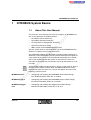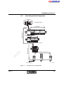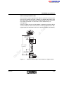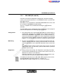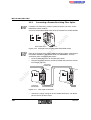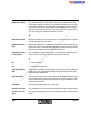
1
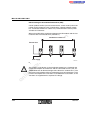
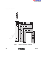
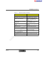
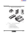
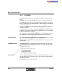
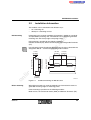
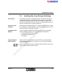
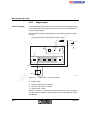
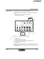
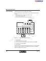
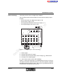
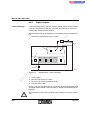
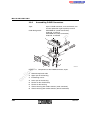
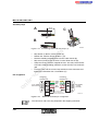
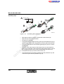
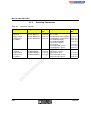
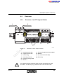
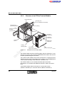
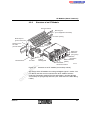
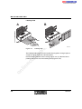
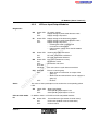
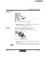
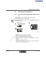
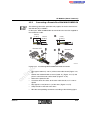
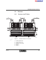
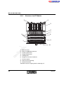
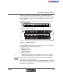
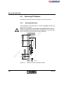
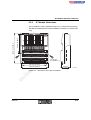
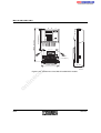
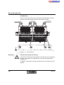
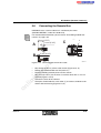
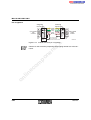
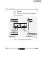
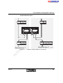
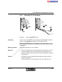
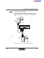
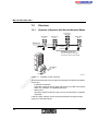
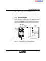
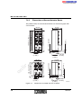
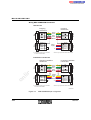
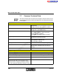
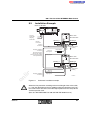
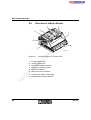
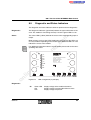
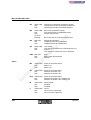
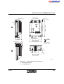
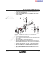
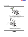
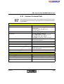
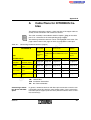
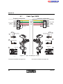
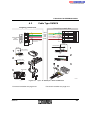
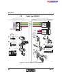
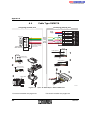
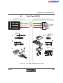
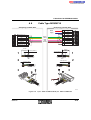
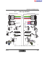
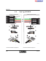
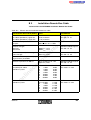
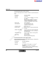
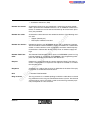
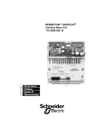
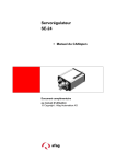
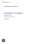
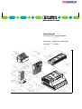
ST Modules (Smart Terminals)
4.2
Structure
4.2.1
Structure of an ST Compact Station
2
IN
U S
T E R
IB S T M E 2 4 D IO
U S
B A
E
1
L D
2
3
4
5
6
7
8
K 1
K 2
nt
C C
B A
C C
K 3
K 4
K 5
K 6
K 7
K 8
ne
8 d ig ita l In p u t , 8 r e la y O u tp u t
2 4 V D C , M o d u le Id e n t.: 1 9 1
9
in
ec
om
8
po
1 0
on
l
Figure 4-1
IN
, O rd . N o .: 2 7 5 1 8 3 6
U s 1
U L
U L
8 /8 R /3
B
T E R
F
F
B
s.
F
F
B
3
E
T E R
U S
E
IN
U S
E
U S
E
U S
co
m
1
4
U S
U s 1
E 1
U s 2
E 2
U L
C C
B A
1
2
3
4
5
6
7
8
6
5
7
5 1 0 9 B 0 0 1
Structure of an ST compact station
1
Incoming remote bus
7
ST cable (supplied with the module)
2
Outgoing remote bus
8
Module 1
3
Dummy plug
9
Bus terminal module (BK)
4
Grounding terminal
10 End clamp
5
Protective earth ground
6
Module 2
Use a dummy plug to isolate the open local bus connection of the last
ST module. The dummy plug is delivered with each ST BK module.
6000AC02
4-5