1
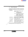
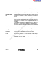
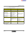
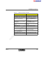
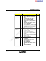
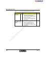
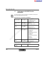
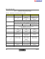
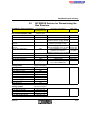
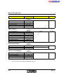
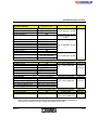
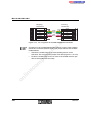
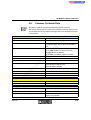
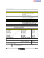
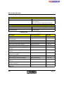
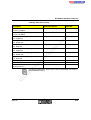
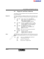
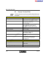
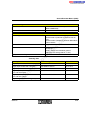
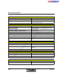
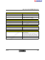
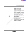
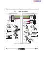
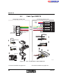
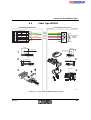
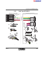
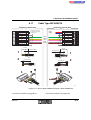
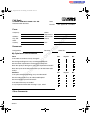
IBS SYS PRO INST UM E
3.1.2
Specifications for installation remote bus cables*
Order No.
IBS INBC METER/S
IBS INBC METER/E
27 23 13 6
27 59 87 0
27 23 15 2
For fixed wiring
Partially welding-resistant
For highly flexible
applications
Partially welding-resistant
For permanent indoor
and outdoor installation (even underground)
co
Application
IBS INBC METER
m
Table 3-2
Installation Remote Bus Cables
With additional wires for the power supply
3 x 2, twisted-pair (data), 3 single wires (power),
with common shielding (braided shield consisting of high-grade steel)
nt
s.
Structure
DIN 47100
Pink, gray, yellow, green, white, brown (data)
Blue, red, green/yellow (power)
po
ne
Color coding of the
wires
Additional reinforced
PVC outer sheath
0.25 mm² [24 AWG]
(data)
1.0 mm2 [18 AWG]
(power)
0.22 mm² [24 AWG]
(data)
1.0 mm2 [18 AWG]
(power)
Outside diameter
7.9 mm (0.311 in.)
7.9 mm (0.311 in.)
9.4 mm (0.370 in.)
Outer cable sheath
Green (RAL 6017),
flame-retardant
Green (RAL 6017),
flame-retardant
halogen-free
Black (RAL 9005), UV
resistant
Operating temperature
Fixed
-30°C to +70°C
(-22°F to +158°F)
Fixed
-30°C to +70°C
(-22°F to +158°F)
Fixed
-30°C to +70°C
(-22°F to +158°F)
on
l
in
ec
om
0.22 mm² [24 AWG]
(data)
1.0 mm2 [18 AWG]
(power)
Cable diameter
Flexible
-5°C to +70°C
(+23°F to +158°F)
Weight
8.5 kg/100 m (328 ft.)
9.5 kg/100 m (328 ft.)
12.8 kg/100 m (328 ft.)
Bending radius
Fixed at least 64 mm
(2.520 in.)
Flexible at least
119 mm (4.685 in.)
Fixed at least 76 mm
(2.992 in.)
Operating capacity
3-8
65 nF/km at 800 Hz, maximum
6000AC02