1
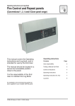
GasRelease Panel User Manual & Log Book MAN1806-1 \ MAN1806 Revision: 29 July 2009 GAS RELEASE PANEL USER MANUAL & LOG BOOK CONTENTS IMPORTANT SAFETY NOTES.................................................................................................................... 3 BASIC OVERVIEW AND KEY FEATURES ................................................................................................. 4 CONTROLS AND INDICATORS ................................................................................................................. 5 LCD Unit.................................................................................................................................................. 5 LED Indicators ......................................................................................................................................... 5 Push button Controls ............................................................................................................................... 7 Key Switch Controls................................................................................................................................. 7 ACCESSING THE MENU CONTROLS ........................................................................................................ 8 Overview ................................................................................................................................................. 8 Selecting the Menus and Sub-Menus ....................................................................................................... 8 General User Controls (Access Level 1)................................................................................................... 9 Authorised User Controls (Access Level 2) ............................................................................................ 10 Disablements......................................................................................................................................... 11 SYSTEM SET-UP DATA CHART .............................................................................................................. 13 FIRE ALARM/GAS PANEL LOG BOOK ................................................................................................... 14 ©2009. No responsibility can be accepted by the manufacturer or distributors of this range of extinguisher panels for any misinterpretation of an instruction or guidance note or for the compliance of the system as a whole. The manufacturer’s policy is one of continuous improvement and we reserve the right to make changes to product specifications at our discretion and without prior notice. E&OE. 2 GAS RELEASE PANEL USER MANUAL & LOG BOOK IMPORTANT SAFETY NOTES The Gas Release Panel is safe to operate provided it has been installed in compliance with the manufacturer’s instructions and used in accordance with this manual. Lethal voltages are present inside the panel. DO NOT operate the panel with its enclosure open. There is no need to open the enclosure except to carry out commissioning, engineering, or maintenance work. This work must only be carried out by competent service personnel who are fully conversant with the contents of the separate installation manual for this product and have the necessary skills for maintaining this equipment. If the enclosure is damaged in any way, expert advice should be sought regarding its repair. Regular servicing of the Gas Release panel and extinguishing system is highly recommended, preferably on a continuous maintenance contract and by a competent organisation. A full itemised report of the installation should be obtained at least annually. 3 GAS RELEASE PANEL USER MANUAL & LOG BOOK BASIC OVERVIEW AND KEY FEATURES The GasRelease panel acts as both a conventional fire alarm panel and an automatic extinguisher control panel. The GasRelease panel’s features include the following: Time-stamped event log Abort and hold functions for cancelling, or delaying the extinguishant release sequence Front-panel mounted LCD unit displays system status and facilitates system programming Front-panel mounted extinguisher release button and two keyswitches; one to enter access mode and one to toggle between automatic/manual modes of operation Three-zone conventional detector circuits, line monitored for open and short-circuit faults. Any zone combination can be programmed to activate an alarm and initiate the extinguishant release sequence Three conventional alarm sounder circuits (two x 1st stage, one x 2nd stage), line monitored for open and short-circuit faults Monitored inputs for: Manual Release, Flow Switch, Low Pressure, Mode, Hold and Abort Auxiliary outputs for: Fire, Local Fire, Extract, 1st Stage, 2nd Stage, Fault Extinguishing output supports up to 2 x solenoids, or multiple ‘Metrons™’ Adjustable extinguishant release time delay, duration and flooding time Alarm counter to record the number of times the panel has been in an alarm state Optional Output Expansion Relay Board providing additional relay outputs for: Reset, Mode, Discharged, Hold and Abort Connections for up to eight Remote Status Units (RSU) which provide remote indication of system status on an LCD unit, with mode select and manual extinguisher release Connections for up to eight Economy Status Units (ESU) to provide remote indication of system status with mode select. Pushbutton and keyswitch entry to two access levels (displayed on the LCD unit).Access Level 1 (AL1) is for general users, Access Level 2 (AL2) is for authorised users. 4 GAS RELEASE PANEL USER MANUAL & LOG BOOK CONTROLS AND INDICATORS The front of the GasRelease panel has various LED indicators, pushbuttons, keyswitches and an LCD unit, as shown in Figure 1 below: Figure 1: Front Panel Controls and Indicators LCD Unit This unit provides system status information, counts down the time for extinguishant release and displays Access Levels 1 & 2 menus and sub-menus. LED Indicators The LED indicators on the front of the panel give a comprehensive overview of the system’s current status. Any fire and fault conditions are clearly displayed, disablements highlighted and the status of all inputs and outputs displayed. The table below summarises the various indicators and what they mean in their various states. Indicator Status Description Flashing - Red Panel has detected a fire alarm condition on a fire zone. Steady - Red The fire alarm has been silenced. Flashing - Red A fire alarm condition has been detected on the associated zone Steady - Red A fire alarm condition has been silenced on the associated zone Flashing - Yellow A hold input has been received at the panel Steady - Red First Stage extinguishant output has been activated Steady - Red Countdown timer to extinguishant release has started. Steady - Red A flow switch input (from a flow switch on the extinguishant cylinder) is received at the panel Steady - Yellow An abort input has been received at the panel 5 GAS RELEASE PANEL USER MANUAL & LOG BOOK Steady - Yellow Part of the system has been manually disabled and/or one or more of the fire zones has a delay applied to them Flashing - Yellow Faulty wiring, or detector removed from base on the flashing zone Steady – Yellow The zone has been disabled Flashing - Yellow The zone is in test mode Steady - Yellow Extinguishant release output has been disabled Steady - Yellow Manual Release facility has been disabled Steady - Yellow First stage contact has been disabled Steady - Yellow Second stage contact has been disabled Steady - Yellow Indicates all panel sounders are disabled Steady - Yellow Indicates the status of the extinguishant system is “Manual Only” mode Steady - Yellow Indicates the status of the extinguishant system is “Manual & Automatic” mode Steady - Green The panel is supplied with power Flashing – Yellow The panel has detected a fault with its power supply, or backup batteries Steady - Yellow The panel mounted keyswitch has been turned to the “Accessed” position and the panel is in Access level 2 Flashing – Yellow The panel is in test mode Flashing – Yellow Indicates a fault has been detected on the system Flashing – Yellow The panel has detected a microprocessor fault Steady – Yellow Delays have been programmed into the panel Flashing – Yellow A delay is currently running Flashing – Yellow Faulty wiring (short or open circuit) has been detected on the panel’s sounder outputs Steady - Yellow The alarm sounders have been disabled Flashing – Yellow Indicates a short or open circuit on extinguishant output 6 GAS RELEASE PANEL USER MANUAL & LOG BOOK Flashing – Yellow Indicates these is low pressure in the extinguishant system, or there is a short or open circuit fault on the low pressure switch input Push button Controls Push Button Description Dependant on the status of the panel, the push buttons: Scroll vertically through any fire, prealarm or fault conditions that appear on the LCD screen Scroll vertically through the user menus Manipulate date, time, disablement settings etc Dependant on the status of the panel, the push buttons: Scroll horizontally through the user menus Escape, or accept options available in the user menus Provides access to Access level 1 menu Silences the panel’s internal sounder at anytime Resets the panel after the sounders have been silenced (Access level 2 only) Silences, or resounds the system’s sounders (Access level 2 only). Note: This push button will not silence 2nd stage alarm if the extinguishant is about to be released. CAUTION: THESE PUSH BUTTONS MANUALLY RELEASE THE EXTINGUISHANT Pull down the flap and press both buttons to release the extinguishant Key Switch Controls Insert and turn the panel-mounted keyswitch to the “accessed” position to enter Access Level 2 (Authorised User level). Turn and remove the keyswitch to exit Access Level 2. Insert and turn the panel-mounted keyswitch to toggle the mode of the extinguishant system between “Manual Only” and “Manual & Automatic”. NOTE: WHEN THE PANEL IS IN MANUAL MODE, EXTINGUISHANT CANNOT BE RELEASED BY AUTOMATIC FIRE DETECTION. MODE SELECT KEYSWITCHES ARE ALSO MOUNTED ON REMOTE STATUS UNITS (RSU) AND ECONOMY STATUS UNITS (ESU) AND OTHER DEVICES. ANY ONE KEYSWITCH IN THE MANUAL POSITION TAKES CONTROL OF THE SYSTEM MODE. 7 GAS RELEASE PANEL USER MANUAL & LOG BOOK ACCESSING THE MENU CONTROLS Overview Two levels of menu controls are available on the GasRelease panel; Access Level 1 (AL1) for General Users and Access Level 2 (AL2) for Authorised Users. All menus are displayed at the LCD unit as detailed in Figure 2, below: Note: When selected, menus and sub-menus change from Title Case to UPPERCASE Figure 2: Overview of Access levels 1 and 2 menus Selecting the Menus and Sub-Menus 1. To en t er Access Level 1 m en u p r ess t h e Men u p u sh b u t t o n , o r t o en t er Access Level 2 m en u t u r n t h e p an el -m o un t ed keysw it ch t o t h e “accessed ” p o sit io n . 2. Pr ess t h e “UP” an d “DOWN” b u t t o n s t o h ig h ligh t a m en u . 3. Pr ess t h e “OK” b u t t o n t o select a m en u . 4. Pr ess t h e “OK” b u t t o n t o select a su b -m en u (if availab le). 5. If ap p licab le, p r ess t h e “UP” an d “DOWN” b u t t o n s t o scr o ll t h e d isp lay t h r o u gh all act ive co n d it io n s (f au lt s, d isab lem en t s, t est s, et c.). 6. Pr ess t h e “ESC” b u t t o n t o r et u r n t o t h e p r evio us m en u . 7. To exit Access Level 1 p r ess t h e “ESC” b u t t o n . No t e: Th e p an el w ill au t o m at ically exit Access Level 1 af t er ap p r o x. 15 secs. o f in act ivit y. To exit 8 GAS RELEASE PANEL USER MANUAL & LOG BOOK Access Level 2 t u r n t h e p an el-m o u n t ed keysw it ch t o t h e NOT “accessed ” p o sit io n . General User Controls (Access Level 1) The functions that can be performed in Access Level 1 are: • Manually activate the extinguisher release • Mute the internal sounder. Also, by pressing the Menu pushbutton the LCD unit displays the following menu: Note: All Access Level 1 menus are available to an Access Level 2 user. Menu Display Faults Display Dis/mnt Zones in Test Lamp Test Alarm Counter Description Displays all faults on the system Displays all disablements on the system Displays all detection zones that are in test mode on the system Illuminates all front panel LED indicators Displays the number of times a fire alarm condition has occurred on the panel Note: A Terminate Delay ‘floating’ menu is also displayed for a level 1 user when there is an alarm on the system and a sounder delay is active. Selecting this menu activates the fire sounders immediately. Display Faults 1. In Access Level 1, select the Display Faults menu. The panel displays all active faults on the system. (e.g. Zone 1 O/C Fault, Zone 2 S/C Fault, etc.) 2. Scroll the display through all active faults using the “UP” and “DOWN” buttons. 3. Press the “ESC” button to return to the Access Level 1 menu. Display Dis/mnt The Display Disablements menu displays all active disablements on the system. An Access Level 2 user sets disablements. 1. In Access Level 1, select the Display Dis/mnt menu. The panel displays all active disablements on the system (e.g. Zone 1 disabled, etc.) 2. Scroll the display through all active disablements using the “UP” and “DOWN” buttons. 3. Press the “ESC” button to return to the Access Level 1 menu. Zones in Test This menu displays all detection zones that are currently in test mode on the system. A system engineer can only put zones into test mode. 1. In Access Level 1, select the Zones in Test menu. The panel displays all zones currently in test on the system (e.g. Zone 1 is on Test, etc.) 2. Scroll the display through all active zones in test using the “UP” and “DOWN” buttons. 3. Press the “ESC” button to return to the Access Level 1 menu. Lamp Test All LED indicators can be tested at anytime by selecting using this menu. 1. In Access Level 1, select the Lamp Test menu. All the panel’s LEDs will illuminate steady for approx. 2 secs. The panel’s internal sounder will also sound. If any LEDs fail to illuminate report the fault to the designated site engineer and make a note in the Log Book. 2. On completion, the display returns to the Access Level 1 menu. Alarm Counter 1. In Access Level 1, select the Alarm Counter menu. The total number of times the panel has been in a fire alarm condition is displayed. 9 GAS RELEASE PANEL USER MANUAL & LOG BOOK 2. Press the “ESC” button to return to the Access Level 1 menu. Authorised User Controls (Access Level 2) The functions that can be performed in Access Level 2, by turning the panel-mounted keyswitch to the “accessed” position, are: • Manually activate the extinguisher release • Mute the internal sounder • Silence the alarm sounders • Resound the alarm sounders • Reset an alarm condition. Also, the LCD unit displays the following menu: Menu Display Faults Display Dis/mnt Zones in Test Lamp Test Alarm Counter Set Time/Date Event Log Disp Contrast Disablements Sub-Menu Show Log Log reset Disable Exting Disable Zone Disable Sounder Disable Sndrdel Disable Input Disable Relay Disable RSU Description See Access Level 1 See Access Level 1 See Access Level 1 See Access Level 1 Displays the number of times a fire alarm condition has occurred on the panel. Also resets the counter. Adjusts the panel’s date & time settings Displays the panel’s event log Resets the panel’s event log Adjusts the contrast of the LCD unit Disables/Enables the extinguishant system Disables/Enables detection zones Disables/Enables fire sounders Disables/Enables fire sounder delay Disables/Enables monitored inputs Disables/Enables auxiliary relay outputs Disables/Enables Remote Status Units Note: Two ‘floating’ menus (Start Extract & Stop Extract) are also displayed for a level 2 user when the Extract Option is selected as fitted by an engineer. These menus appear at the end of the flooding period, prior to reset, and start or stop the ventilation extract fan respectively. Alarm Counter 1. In Access Level 2, select the Alarm Counter menu. The total number of times the panel has been in a fire alarm condition (since last reset) is displayed. 2. Press the “ESC” button to return to the Access Level 2 menu, or to clear the alarm counter, press the “OK” button. The panel requests confirmation to clear to today’s date. 3. Press the “OK” button to reset the counter. The panel will start counting any new fire conditions from the current date. A confirmation message confirms the change has been made and the display returns to the Access Level 2 menu. Set Time/Date 1. In Access Level 2, select the Set Time/Date menu. The panel’s current time setting is displayed. 2. Use the “UP” and “DOWN” buttons to adjust the hour (the panel has a 24 hour clock). 3. When the correct hour is displayed, press the “OK” button to move to the minutes field. 4. Use the “UP” and “DOWN” buttons to adjust the minutes. 5. When the correct time is displayed, press the “OK” button to alter the date. 6. Use the “UP” and “DOWN” and “OK” buttons to set the day/month/year, as appropriate. 7. When correct, press the “ESC” button to return to the Access Level 2 menu. 10 GAS RELEASE PANEL USER MANUAL & LOG BOOK Event Log 1. In Access Level 2, select the Event Log menu, select Show Log sub-menu. The panel’s last event log is displayed. 2. Use the “UP” and “DOWN” buttons to view the previously saved events. When the log is full, the newest record replaces the oldest record. Events are listed in chronological order. 3. Press the “ESC” button to return to the previous menu. 4. To reset the panel’s event log, in Access Level 2, select the Event Log menu, then select Log Reset sub-menu. The panel requests confirmation to erase the event log. 5. Press the “OK” button to confirm and the event log is cleared from the panel’s memory. 6. Press the “ESC” button to return to the previous menu. Disp Contrast 1. In Access Level 2, select the Disp Contrast menu. The panel’s current LCD display contrast is displayed. 2. Use the “UP” and “DOWN” buttons to adjust the contrast of the LCD unit. 3. Press the “OK” button to confirm the new setting and return to the Access Level 2 menu. Disablements The Disablements menu allows the temporary disabling, or enabling of the extinguishant system, detection zones, sounders, monitored inputs, relays and RSUs. Typically used when there are input/output faults and for system testing. Any active disablements are displayed at the Gas release panel by the General Disablement and relevant disablement yellow LEDs lit steady. Note: It is recommended all disablements are immediately enabled when no longer required as they can have a major effect on how the system works. Disable Exting This sub-menu allows the disabling/enabling of the extinguishant system. 1. From the Disablements menu, select the Disable Exting sub-menu. 2. Press the “OK” button to disable/enable the extinguishant system. 3. Press the “ESC” button to return to the Disablements menu. Note: ‘Exting System Disabled’ will also be displayed at any Remote Status Units (RSUs) connected on the system. Disable Zone This sub-menu allows the disabling/enabling of one, or more of the panel’s three detection zones. Disabled zones do not report fire, or fault conditions. 1. From the Disablements menu, select the Disable Zone sub-menu. 2. Select the detection zone(s) to be disabled/enabled using the “UP” and “DOWN” buttons. 3. Press the “OK” button to disable/enable a selected zone. 4. Press the “ESC” button to return to the Disablements menu. Disable Sounder This sub-menu allows the disabling/enabling of the fire sounders from sounding in a fire condition. 1. From the Disablements menu, select Disable Sounder. 2. Press the “OK” button to disable/enable the sounder circuit. 11 GAS RELEASE PANEL USER MANUAL & LOG BOOK 3. Press the “ESC” button to return to the Disablements menu. Disable SndrDel Th e so un d er d elay su b -m en u allo w s t h e d isab lin g /en ab lin g o f a f ir e so u n d er d elay in a f ir e co n d it io n . 1. Fr o m t h e Disab lem en t s m en u , select Disab le Sn d r Del. 2. Pr ess t h e “OK” b u t t o n t o d isab le/en ab le t h e d elay o n t h e so u n d er cir cu it . 3. Pr ess t h e “ESC” b u t t o n t o r et u r n t o t h e Disab lem en t s m en u . Disable Input Th is su b -m en u allo w s t h e d isab lin g /en ab lin g o f o n e, o r m o r e o f t h e p an el’s six m o n it o r ed in p u t s: Man u al Release, Flo w Sw it ch , Lo w Pr essu r e, Mo d e, Ho ld an d Ab o r t . 1. Fr o m t h e Disab lem en t s m en u , select Disab le In p u t . 2. Select t h e in p u t (s) t o b e d isab led /en ab led u sin g t h e “UP” an d “DOWN” b u t t o n s. 3. Pr ess t h e “OK” b u t t o n t o d isab le/en ab le t h e select ed in p u t . 4. Pr ess t h e “ESC” b u t t o n t o r et u r n t o t h e Disab lem en t s m en u . Disable Relay Th is su b -m en u allo w s t h e d isab lin g /en ab lin g o f o n e, o r m o r e o f t h e p an el’s six au xiliar y r elay o u t p u t s: Fir e, Lo cal Fir e, Ext r act , 1st St ag e, 2n d St ag e an d Fau lt . Note: If an Ou t p u t Exp an sio n Relay Bo ar d is f it t ed , t h is su b -m en u also allo w s t h e d isab lin g /en ab lin g o f o n e, o r m o r e o f t h e car d ’s f ive r elay o u t p u t s: Reset , Mo d e, Disch ar g ed , Ho ld an d Ab o r t . 1. Fr o m t h e Disab lem en t s m en u , select Disab le Relay. 2. Select t h e r elay o u t p u t (s) t o b e d isab led /en ab led u sin g t h e “UP” an d “DOWN” b u t t o n s. 3. Pr ess t h e “OK” b u t t o n t o d isab le/en ab le t h e select ed r elay o u t p u t . 4. Pr ess t h e “ESC” b u t t o n t o r et u r n t o t h e Disab lem en t s m en u . Disable RSU Th is su b -m en u allo w s t h e d isab lin g /en ab lin g o f o n e , o r m o r e o f t h e p an el’s Rem o t e St at u s Un it s. 1. Fr o m t h e Disab lem en t s m en u , select Disab le RSU. 2. Select t h e RSU(s) t o b e d isab led /en ab led u sin g t h e “UP” an d “DOWN” b u t t o n s. 3. Pr ess t h e “OK” b u t t o n . Th e p an el r eq u est s co n f ir m at io n . 4. Pr ess “DOWN” t o co n f ir m t h e ch an g e. 5. Pr ess t h e “OK” b u t t o n t o d isab le/en ab le t h e select ed RSU. Th e Disab lem en t s m en u is d isp layed . Note: ‘RSU Disabled’ will be displayed at the RSU that has been disabled. 12 GAS RELEASE PANEL USER MANUAL & LOG BOOK SYSTEM SET-UP DATA CHART Important: This chart should be completed by an authorised engineer prior to system handover. Complete the appropriate setting box. Function Setting Description The zone (Z1, Z2, Z3) combination that starts the extinguishant release sequence ZONE SELECTION ………………..secs The countdown duration before the extinguishant is released. Adjustable between 0 – 60 secs. EXTINGUISHANT DURATION ………………..secs The duration of the firing signal to the extinguishant output. Adjustable between 1-300 seconds. FLOODING TIME ………………..secs The duration for release of extinguishant. Adjustable between 60-1740 seconds. EXTRACT OPTION FITTED …….. NOT FITTED … Selects whether a ventilation extract fan is fitted, or not. EXTRACT TIME ………………..secs The duration for the ventilation extract fan operation. Adjustable between 1-900 seconds. FLOW OPTION FITTED …….. NOT FITTED … Selects whether a flow switch is fitted, or not. SOUNDER DELAY ………………..secs The time delay before the fire sounders operate. Adjustable between 0-600 seconds. EXT OUTPUT EOLS 1 x EOL ……….… 2 x EOL …………. The number of extinguisher System Line Terminators. Set at either 1 or 2. MODE EXEPTIONS MODE FAULT: Manual Only Auto/Manual MODE DISABLED: Manual Only Auto/Manual The default setting when the mode input is in Fault and/or Disabled. Set at either Manual Only or Auto/Manual mode. EARTH FAULT ENABLED .……. DISABLED ……. Enables, or disables the panel’s earth fault monitoring. MANUAL RELEASE MODE DELAYED ……. IMMEDIATE ….. The manual release of extinguishant is delayed, or immediate. Extinguishant delay remains active on automatic detection. EXTINGUISHANT DELAY Additional Information Any additional information the user needs to be aware of is detailed below: THE INFORMATION ABOVE WAS COMPLETED BY (NAME): _____________________________ OF (COMPANY): _______________________________________ ON (DATE):____/____/____ 13 GAS RELEASE PANEL USER MANUAL & LOG BOOK FIRE ALARM/GAS PANEL LOG BOOK It is recommended that this log book be maintained by a responsible person, who should ensure that every entry is properly recorded. In the UK, this is necessary to satisfy the recommendations of BS5839-1, compliance with which may be a requirement of legislation. If your premises are certificated under the Fire Precautions Act 1971, failure to keep a suitable log book may be a breach of the requirements of the certificate, which is a criminal offence. In order to satisfy the requirements of BS5839-1, the following must be recorded: Name of the responsible person Brief details of the maintenance arrangements Dates and times of all tests, including fire drills Dates and times of all fires to which the system responds Dates and times of all false alarms Causes, circumstances surrounding, and category of false alarms (if known) The identity of any fire detector that triggers any of the above fire alarm/extinguisher signals (if known) Dates, times and type of all faults and defects The dates and times of all maintenance (e.g. service visit, or non-routine attention). USER: SITE ADDRESS: RESPONSIBLE PERSON(S) ON SITE: THE SYSTEM WAS DESIGNED BY: THE SYSTEM WAS INSTALLED BY: THE SYSTEM WAS COMMISSIONED BY: THE SYSTEM WAS ACCEPTED BY: FOR SERVICE (DETAILS OF WHO YOU SHOULD CONTACT IF MAINTENANCE IS REQUIRED) THE SYSTEM IS MAINTAINED UNDER CONTRACT BY: Company:______________________________________________________________________ Address:_______________________________________________________________________ ______________________________________________________________________________ Contact number:__________________________________ Expiry Date:____________________ NORMAL HOURS (MON-FRI) TEL: _________________________________________________ OUTSIDE NORMAL HOURS TEL: __________________________________________________ MANNED CENTRE TEL: __________________________________________________________ MANNED CENTRE CODE: ________________________________________________________ NORMAL MAXIMUM ATTENDANCE TIME FOR A MAINTENANCE TECHNICIAN IS: __________ EXPENDABLE COMPONENT REPLACEMENT PERIODS (LIST): 14 GAS RELEASE PANEL USER MANUAL & LOG BOOK Details of tests (including fire drills), actual fire alarms, disablements, enablement and faults should be recorded here. False alarms and maintenance work should be recorded on page 19. DATE TIME EVENT e.g. test, fire alarm signal, fault ZONE DEVICE 15 ACTION REQUIRED COMPLETED INITIALS GAS RELEASE DATE TIME PANEL USER MANUAL & LOG BOOK EVENT e.g. test, fire alarm signal, fault ZONE DEVICE 16 ACTION REQUIRED COMPLETED INITIALS GAS RELEASE DATE TIME PANEL USER MANUAL & LOG BOOK EVENT e.g. test, fire alarm signal, fault ZONE DEVICE 17 ACTION REQUIRED COMPLETED INITIALS GAS RELEASE PANEL USER MANUAL & LOG BOOK False Alarms DATE TIME ZONE DEVICE THAT TRIGGERED ALARM SIGNAL CAUSE (IF KNOWN) BRIEF CIRCUMSTANCES (WHERE CAUSE IS UNKNOWN RECORD ACTIVITIES IN AREA) MAINTENANCE VISIT REQUIRED? (YES OR NO) FINDINGS OF MAINTENANCE TECNICIAN CATEGORY OF FALSE ALARMS FURTHER ACTION REQ. DONE PLEASE TICK Maintenance Work DATE TIME ZONE (WHERE APPLICABLE) DEVICE (WHERE APPLICABLE) REASONS FOR WORK 18 WORK CARRIED OUT FURTHER WORK REQ. SIGNATURE GAS RELEASE PANEL USER MANUAL & LOG BOOK UNCONTROLLED DOCUMENT NOTE: Due to Ampac’s commitment to continuous improvement specifications may change without notice. 19