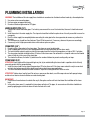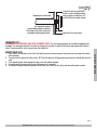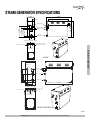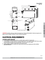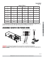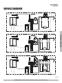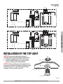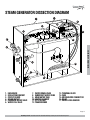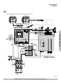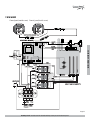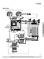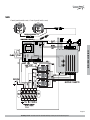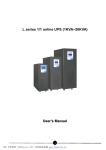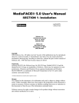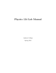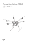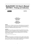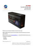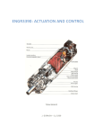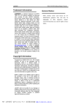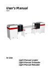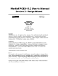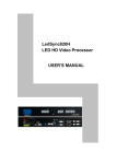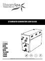
1
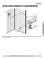
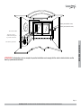
STEAM BATH GENERATOR USER GUIDE
AUTO
D
HI
S P E R Q UI
ET
IN
RA
EA
T
Steam Spa PHONE: 516-986-5325 FAX: 866-560-5662 http://steamspa.com [email protected]
-IN
W
T
UOUS S
T
TIN
B UIL
K S TA R
CON
UIC
Q
4.5KW
6KW
7.5KW
9KW
10.5KW
12KW
15KW
M
MODELS
TABLE OF CONTENTS
PROLOGUE........................................................................................................................3
USER INSTRUCTIONS..........................................................................................................3
CHOOSING THE RIGHT LOCATION...........................................................................................3
INSTALLATION DRAWING OF STEAM GENERATOR......................................................................4
PLUMBING INSTALLATION....................................................................................................6
STEAM GENERATOR SPECIFICATIONS......................................................................................8
ELECTRICAL REQUIREMENTS................................................................................................9
ASSEMBLY GRAPH FOR POWER WIRE................................................................................... 10
STEAM GENERATOR DISSECTION DIAGRAM............................................................................ 13
CARE & USE FOR THE CONTROL PANEL................................................................................. 14
CONTROLLER BOX CONTENT............................................................................................... 14
CONTROL PANEL INSTALLATION INSTRUCTIONS...................................................................... 15
TESTING THE MACHINE...................................................................................................... 16
CONTROL PANEL DIAGRAM................................................................................................. 16
CONTROL PANEL OPERATION.............................................................................................. 17
STEAM GENERATOR MAINTENANCE...................................................................................... 18
TECHNICAL PARAMETERS................................................................................................... 20
WIRING DIAGRAMS........................................................................................................... 21
Page 2
SteamSpa PHONE: 516-986-5325 FAX: 866-560-5662 http://steamspa.com [email protected]
INSTALLATION & USER GUIDE
INSTALLATION OF THE TOP LIGHT......................................................................................... 12
PROLOGUE
Thank You for choosing SteamSpa for health, beauty and relaxation. Now you can enjoy your own private sanctuary in the comfort
of your own home. Let your stress melt away as you relax in your state of the art Steam Room.
For Centuries people have recognized the health benefits of saunas. Leave your stress behind and enter a world of total relaxation,
ridding you of pain, toxins, and sore muscles as well as increasing your blood circulation etc., leaving your skin glowing. Besides
these physical effects, a SteamSpa Session will leave you totally relaxed by providing you a peaceful and relaxing environment
away from all.
Our advanced technology, engineering, and product development provides Steam Generators that enhance the lifestyles of people
throughout the world. SteamSpa is continuously refining, updating and developing their products assuring the optimum quality
and performance of their products. Working with the industries top engineers we have developed the most efficient, dependable
and highest quality products.
1. Check for visible damages upon delivery of Generator. Any damages to packaging should be reported immediately to shipping
company delivery representative and SteamSpa’s Customer Service Dept.
2. Check model and accessories are correct, including voltage input. Any discrepancies are to be reported to SteamSpa’s
Customer Service Dept. within 48 hours of delivery.
3. Read installation instructions in detail for a secure and effective installation of SteamSpa generators.
4. SteamSpa recommends the use of a licensed plumber and electrician for proper installation of SteamSpa generators.
5. SteamSpa shall not be responsible for product damage or malfunction caused by self-installation or installation procedures
which do not comply with user manual.
6. SteamSpa generators are for indoor use only.
CHOOSING THE RIGHT LOCATION
1. The distance to the steam room should be less than 20ft, the standard pipe which links the controller and the steam generator
should be 20ft.
2. The steam generator should not be installed in the steam room
3. Do not install outdoor or in any places that will influence the performance of the machine by the environment.
4. Do not install in a frigid location or any places where the water will freeze.
5. Do not install near flammable chemicals.
6. Install in a dry place where the ventilation is good.
7. Install an exhaust fan outside of the steam room for the excess steam to be expelled from the shower room.
8. The steam generator has a hanging groove for wall installations..
9. Both sides and the top of the steam generator need to reserve at least 12 inches space.
10. The area where the machine is installed must be easily cleaned up and convenient for the disassembly of the machine.
11. The installation area must be convenient for the steam generator draining system.
12. The steam tube, safety valve, drain valve, water tube and steam outlet remain very heated after the steam generator has
stopped working for some time.
13. The controller must be installed in the steam room opposite to the steam head, please read the instructions for the controller’s
installation and operation.
Page 3
SteamSpa PHONE: 516-986-5325 FAX: 866-560-5662 http://steamspa.com [email protected]
INSTALLATION & USER GUIDE
USER INSTRUCTIONS
INSTALLATION DRAWING OF STEAM GENERATOR
Control panel
Supply
Pressure Relief Valve
Steam Generator
Water Inlet Pipe
Water Drain Valve
Steam Outlet
ATTENTION! The drawing is only for explanation purposes. As for practical design of steam room, please consult with a qualified
designer, architect or builder.
Page 4
SteamSpa PHONE: 516-986-5325 FAX: 866-560-5662 http://steamspa.com [email protected]
INSTALLATION & USER GUIDE
Steam
Outlet
Pipe
Light
Control panel(inside room)
Control panel(outside room)
The steam outlet
The spare place
under the wash pan
£ possible location £
ATTENTION! The illustration is just an example; the practical installation must comply with the nation’s electrical criteria, and be
done by a professional electrician.
Page 5
SteamSpa PHONE: 516-986-5325 FAX: 866-560-5662 http://steamspa.com [email protected]
INSTALLATION & USER GUIDE
The steam generator
PLUMBING INSTALLATION
WARNING! The installation of all water supply lines should be in accordance to all national and local codes by a licensed plumber.
1. Use unions when connecting pipes.
2. Use brass pipes or copper hoses only.
3. Do not use black and galvanized or PVC pipes.
WATER SUPPLY PIPE (1/2’’)
1. Connect hot water or cold water pipes. The Industry recommends the use of a hot water line; However it should not exceed
160¨F.
2. Install stop valve in the water supply line. The stop valve should be installed in a place where it is easily accessible in case of an
emergency.
3. Flush the water supply line completely before connecting the water pipe to the steam generator, to remove any sediments in
the water.
4. The water pressure should be at best between 15 and 20 lbs/square inch. If necessary, decrease the pressure accordingly.
5. If necessary, install a Hydro pneumatic device which reduces pressure spikes.
1.
2.
3.
4.
Do not install any stop valves in the steam pipes. The steam can never be obstructed.
Install a copper pipe of 3/4 inch as the steam pipe between the steam generator and the steam nozzle.
The heat insulation material used to insulate the steam pipe should be resistant to temperatures as high as 250 F or higher.
The steam pipe should be installed inclining 1/4 inches to the steam room. Do not bend it in a shape to make sure that cooled
water will not stay in the curve of the steam pipe.
5. The shorter the distance, the better. Try to decrease the number of elbows to prevent creating valleys or traps.
STEAM HEAD (3/4’’)
ATTENTION! Steam Head and the steam outlet get very hot, try to avoid installing the steam head in a position which will easily
come into contact with the person bathing.
1. Install the steam head 6 inches above the ground and 12 inches from wall. If the steam room material is acrylic or non-heatresistant sheet, please consult with material manufacturer about steam room applications.
2. The steam head outlet should be installed face down. To prevent scalding bather with steam or water.
ATTENTION! Tighten steam head by hand. Do not use a spanner or other tools, use a little soap water and soft sponge to wipe,
and do not use erosive chemical solutions or crude cleaning tools.
IMPORTANT!
1. Please consult manufacturer of materials like acrylic, fiber glass or other anti-heat sheet about the installation of the steam
head.
2. In the entire steam room, it is required that steam does not leak out. The pipes, its accessories and the holes should be air
proof by applying glue so that no steam will enter the holes in the wall.
Page 6
SteamSpa PHONE: 516-986-5325 FAX: 866-560-5662 http://steamspa.com [email protected]
INSTALLATION & USER GUIDE
STEAM PIPE (3/4’’)
Airproof green material belt
Use airproof silica gel or
corresponding airproof material to
fill the gaps in the wall to achieve the
water-proof and damp-proof effect.
If non-heat-resistant material like
acrylic is used as building material,
reserve a gap no smaller than 1/4’’
and fill with heat-insulated material.
Inside wall in the steam room
DRAINPIPE (1/2’’)
ACCORDING TO THE NATIONAL AND LOCAL PLUMBING CODES: The steam generator drain valve should be equipped with a
drainpipe. The steam generator drains the water by using gravity, and pitch is required. Check local code requirements for drain
valves. Do not connect the safety valve or steam line to drain line.
1. Safety valve is an automatic system that is actuated by pressure in order to prevent steam pressure increasing in the interior
of the generator .
2. The pressure limit range of the safety valve is 15 PSI and the pressure will begin to decrease if pressure should come over this
value.
3. If it is allowed by local codes, provide the safety valve with exterior drainpipe.
4. Do not dismantle the pressure relief valve while generator is in operation..
5. To maintain the proper automatic operation of the safety valve, make sure the safety valve connection pipe is smooth.
Page 7
SteamSpa PHONE: 516-986-5325 FAX: 866-560-5662 http://steamspa.com [email protected]
INSTALLATION & USER GUIDE
SAFETY VALVE (3/4’’)
STEAM GENERATOR SPECIFICATIONS
395mm
304mm
142mm
43mm
266mm
302mm
Safety valve
Water inlet
32mm
188mm
151mm
206mm
Steam outlet
Water
drainage
62mm
72mm
Fuse for wire power supply
C o n tr o lle r w ir e
and light wire hole
Power wire hole
INSTALLATION & USER GUIDE
Fuse for wire
power supply
4.5kW
Steam outlet
3 7 0 mm
S a fe t y
valve
1 8 0 mm
2 6 0m m
Water inlet
30mm
Water drainage
30mm
100m m
160m m
400mm
F us e for w ire pow er s upply
C o n tro ller w ire
an d lig h t w ir e
hole
P ow er w ire hole
Fuse for wire
power supply
6kW/7.5kW/9kW
Page 8
SteamSpa PHONE: 516-986-5325 FAX: 866-560-5662 http://steamspa.com [email protected]
535mm
435mm
234mm
Steam outlet
34mm
35 0mm
273mm
183mm
Water inlet
38 5mm
Safety valve
Water
drainage
Fuse for wire power supply
Controller wire and
light wire hole
Power wire hole
10.5kW/12kW/15kW
ATTENTION! To facilitate maintenance, keep the steam engine clean. If the information provided is limited, do not operate on the
pipeline and electric equipment arbitrarily as shown in the figure for proportion.
ELECTRICAL REQUIREMENTS
ELECTRICAL SUPPLY CIRCUITRY
1. Test the voltage of the power supply and make sure suitable voltage is used for the steam generator.
2. Insulated copper wire should be used with an anti-heat temperature of 90 C and a specified voltage of 300V. Refer to national
or local electricity consumption code for the specifications. Refer to the ammeter for the ampere.
3. Connect suitably sized equipment grounding wire into the ground terminal.
4. All the connections must be in accordance with national and local electricity consumption codes and be installed by
professional electricians.
Page 9
SteamSpa PHONE: 516-986-5325 FAX: 866-560-5662 http://steamspa.com [email protected]
INSTALLATION & USER GUIDE
Fuse for wire
power supply
Ty p e
Ap p licab le s p ace o f
the room (cu.Ft. *)
P owe r KW
El e c t ri c i t y
s upply (1PH)
Ele c tr ic
current (A)
Specifications for
power wire (AWG)
S450
90
4.5
240V
19
12
S600
150
6
240V
25
10
S750
225
7.5
240V
32
8
S900
300
9
240V
38
8
S1050
400
10.5
240V
44
6
S1200
450
12
240V
50
6
S1500
500
15
240V
63
6
The data provided above is for 240V single-phased motors. Install an independent circuit breaker between supply line and steam
generator. Install a power disconnect within sight of steam generator to cut-off power when not in use.
ASSEMBLY GRAPH FOR POWER WIRE
Power connection term inal
L1 L2
L2
L1
L1 L2
( 4 . 5 - 1 5 kW )
(240V~ 2PH )
ATTENTION! To avoid damage to the equipment, do not connect electric current directly to heating elements.
WARNING! This graph is for explanation only. For actual installation, refer to national and local electricity consumption codes by
professional electricians.
Page 10
SteamSpa PHONE: 516-986-5325 FAX: 866-560-5662 http://steamspa.com [email protected]
INSTALLATION & USER GUIDE
Ampere Meter
WIRING DIAGRAM
S u p p ly
Wa te r L e ve l Se nsor
T o C ont rol P a ne l
Red ( S h o r t P i n )
Bl ack ( L o n g P i n )
Yel l o w ( M i d d l e P i n )
B lack
R ed
S u p p ly
T o C ont rol P a ne l
J2
Black
White
Drain water valve
Red Red
Fill water valve
B lack
Red J1-2 Red
Red
Red Red
S
Black J1-1 Black
Yel low
R ed
Black
T e rm i na l B l oc k
Ye l l ow / G re e n
J1
B lack
R ed
G
Black J2-1 Blac k
Red ( S h o r t P i n )
Bl ack ( L o n g P i n )
Yel l o w ( M i d d l e P i n )
Red J2-2 Red
Wa te r L e ve l Se nsor
L2 L1
INSTALLATION & USER GUIDE
Black
White
Red Red
Drain water valve
Red Red
Fill water valve
B lack
Red J1-2 Red
J1
Red
S450
S
T e rm i na l B l oc k
Black J1-1 Bla ck
Yellow
R ed
Black
S
G
Ye l l ow / G re e n
B lack
R ed
S
L2 L1
B lack
R ed
S600
S u p p ly
Wa te r L e ve l Se nsor
T o C ont rol P a ne l
Red ( S h o r t P i n )
Bl ack ( L o n g P i n )
Yel l o w ( M i d d l e P i n )
L2 L1
G
J1
T e rm i na l B l oc k
Ye l l ow / G re e n
S750
Fill water valve
Drai n water valve
Red J1-2
Red
Red J2-2
Red
Red J3-2
Black J3-1
Black J2-1
Black J1-1
Black
Red
B lack
Red Red
S
J3
Red
Black
Red Red
S
Black Black
J2
R ed
Black
White
R ed
Yellow
B lack
B lack
R ed
S900
Page 11
SteamSpa PHONE: 516-986-5325 FAX: 866-560-5662 http://steamspa.com [email protected]
S u p p ly
T o C ont rol P a ne l
G
T e rm i na l B l oc k
J1
Red
R ed
S1200
L2
T o C ont rol P a ne l
T e rmi na l B l oc k
J1
INSTALLATION & USER GUIDE
Red
J3-2
B lack
Red
J2
Black
White
B lack
Red Red
Drain water valve
J3-1 Black
Red
Red Red
Fill water valve
Bl ack
J1-1 Black
R ed
Black
S
J2-1 Black
Ye l l ow / G re e n
Black
Bl ack
Yellow
B lack
R ed
Red
Red
Red ( S h o r t P i n )
Bl ack ( L o n g P i n )
Yel l o w ( M i d d l e P i n )
Red
Red
Wa te r L e ve l Se nsor
L1 G
J1-2
S1050
S
J1-2
J2-2
Red
J2
B lack
J2-2
Drain water valve
Black
White
Fill water valve
B lack
Red Red
S
Red Red
S
J2-1 Black
Red
Black
Black
R ed
J1-1 Black
Yellow
R ed
Black
Ye l l ow / G re e n
B lack
Red
Red ( S h o r t P i n )
Bl ack ( L o n g P i n )
Yel l o w ( M i d d l e P i n )
Red
Wa te r L e ve l Se nsor
L2 L1
R ed
S1500
INSTALLATION OF THE TOP LIGHT
CAUTION! The power of the light should not surpass 3
watts(rated power) to prevent the damage of the transformer.
1. A whole set is equipped with AC 12V 3 watt LED lamp.
2. The light should be installed on the ceiling of the steam
room or in a location not accessible to children.
CAUTION! Installer must take some moisture proof measures
in the process of installation. Electrophorus components cannot
be exposed to moisture, as it will cause damage to the light
components causing a possible short circuit.
Tighten N ut
4 5 mm
Rubber G as ket
Ceiling of s team room
LED light
Page 12
SteamSpa PHONE: 516-986-5325 FAX: 866-560-5662 http://steamspa.com [email protected]
STEAM GENERATOR DISSECTION DIAGRAM
2
1
14
16
3
17
15
4
13
12
6
7
11
INSTALLATION & USER GUIDE
5
10
8
9
1. ENCLOSURE
2. INSULATION BRACKET
3. CIRCUIT BOARD
4. STEAM OUTLET
5. PRESSURE RELIEF VALVE
6. WATER FILL VALVE
7. WATER DRAIN VALVE
8. SUBSIDIARY WATER TANK
9. MAIN WATER TANK
10.HEATING ELEMENT
11.221 F HI-LIMIT
12.TRANSFORMER
13.TERMINAL BLOCK
14.FUSE
15.GROUND WIRE CONNECTOR
16.RELAY
17.WATER LEVEL SENSOR
Page 13
SteamSpa PHONE: 516-986-5325 FAX: 866-560-5662 http://steamspa.com [email protected]
CARE & USE FOR THE CONTROL PANEL
1. Use soft cloth with a little soap water to clean the control panel.
2. Do not use crude cleaning tools.
3. If the decorating facade is damaged, contact service electrician to change it.
Do not install any SteamSpa controls without reading and understanding the SteamSpa generator Installation and Instruction
manual. Failure to read and understand these instructions will result in inoperative control, generator, hazardous overheating, and/
or inadequate heating of the steam room.
Do not route control wiring inside or close to power lines conduit, hot water or steam piping. Doing so may result in an inoperative
control, generator, and/or hazardous installation.
Do not install SteamSpa controls with other than SteamSpa compatible steam generators. Doing so may result in possible
generator damage or inoperative installation.
Dual Control Panel with Temperature sensor in Master Control must be installed inside bathing area 5 feet above floor. Do not
install Control directly above Steam Head or below shower head but rather in the seating area on a vertical wall. Doing so may
result in improper temperature reading and/or inoperable control. Slave Control installation location is designed to be installed
outside the steam room.
Turn power to the steam generator off before connecting the control to the generator. Failure to turn the power off generator prior
to connecting controls will result in an inoperable control.
Discontinue use of the steam generator or control if the steam generator is damaged. Continue to do so may result in an
inoperative or hazardous installation.
CONTROLLER BOX CONTENT
•
•
•
•
Control panel
Steam nozzle
User guide
Controller lengthen wire (20 feet)
113mm
23mm
50mm
Page 14
SteamSpa PHONE: 516-986-5325 FAX: 866-560-5662 http://steamspa.com [email protected]
INSTALLATION & USER GUIDE
Single Control Panel with Temperature sensor must be installed inside bathing area 5 feet above floor. Do not install Control
directly above Steam Head or below shower head but rather in the seating area on a vertical wall. Doing so may result in improper
temperature reading and/or inoperable control.
CONTROL PANEL INSTALLATION INSTRUCTIONS
STEP ONE
Determine the installation location of the control panel. The master
control panel is designed to be installed in the steam room only, please
install:
1. 4-5 feet from the ground.
2. Away from the steam head and do not expose under the direct spray
of steam.
3. Install in the perpendicular wall.
4. The position of installation should facilitate easy operation and
convenient wiring.
STEP TWO
Drill a round hole of 1 inch in diameter in a chosen position.
STEP THREE
Control panel
(outside room)
Control panel
(inside room)
Pull control panel wire inside steam room through opening connect it to
the lengthened wire and then to the steam generator and connect with
the corresponding wire in the generator. Connecting the wire of control
panel outside room to the wire of control panel inside the room. When
connecting wires please follow arrows on connector heads for proper
connection. Failure to do so will result in damaging of control pins.
INSTALLATION & USER GUIDE
The controller wire is 1.6 feet long with a controller lengthen wire of 20
feet max. The installation of the controller should be in a position not
more than 25 feet from the steam generator.
Extended wire
STEP FOUR
Start the power supply of steam generator, check and adjust connection,
check each item on the page to make sure all functions work well.
Steam Generator
IMPORTANT! Before adjusting the control panel, make sure the steam
generator is shut off otherwise the control panel may get damaged.
STEP FIVE
Remove the adhesive paper from Control Panel.
To achieve proper adhesion, make sure surface clean, dry and free of
dust.
IMPORTANT! Do not over extend or clip control panel wire as it may
cause possible damage.
STEP SIX
Run a bead of silicone around adhesive gasket. Press Control Panel
against wall at a 12 O’clock position until firmly adhered to surface.
IMPORTANT! Please do not apply an excessive amount of silicone. Just
enough to provide a moisture seal should suffice.
Page 15
SteamSpa PHONE: 516-986-5325 FAX: 866-560-5662 http://steamspa.com [email protected]
TESTING THE MACHINE
1. Make sure the power switch of the control panel is turned on (the control panel displays ---), and the water supply valve will
open.
2. Press the steam switch, , the control panel will display the temperature of the environment, the steam engine begins to
input water to start the steam function, and while opening the steam, press the button to open light function.
3. When there is steam output, press again, the steam will stop and the light will go off automatically.
4. Press the button to start the steam, the steam will come out of the steam generator in no more than 1 minute. Afterwards,
the steam generator will supply water about every minute, the steam will decrease but not stop, and about 10 seconds
later the steam will come out normally. As time goes on, the temperature displayed in the control panel will rise with the
temperature in the room before it stops and stays at the set temperature.
5. Based on different requirements of the user for temperature and steam time, the control panel can adjust temperature and
steam time. While testing the machine, set the time to be 30 minutes and the temperature to be 120F.
6. When the set steam time is due, the system will shut off the steam and light function automatically to stop water input and
steam production .
7. 10 minutes after the steam is shut off, the system will start drainage automatically for 7 minutes. After testing the machine and
it is working properly. Then the machine can be operated normally.
WARNING! Do not dismantle the safety pressure decrease valve arbitrarily.
INSTALLATION & USER GUIDE
IMPORTANT! Do not switch the water input pipe when the steam generator is working.
CONTROL PANEL DIAGRAM
9
7
8
4
1
2
5
M
6
3
10
1. POWER ON/OFF
2. TIME/TEMP SET
3. TIME/TEMP DECREASE
4. TIME/TEMP INCREASE
5. LIGHT ON/OFF
6. MEMORY
7. DIGITAL DISPLAY SCREEN
8. STEAMSPA LOGO
9. FRONT DECORATIVE BEZEL
10.TEMP SENSOR
Page 16
SteamSpa PHONE: 516-986-5325 FAX: 866-560-5662 http://steamspa.com [email protected]
CONTROL PANEL OPERATION
The control panel has a digital temperature control system which can start, stop or pause in the
preset time to keep the temperature at the set number.
Fig.1
ON/OFF
When system is powered, all functions will still not be activated and remain in a waiting state.
Digital tube will display ---- (Fig.1). In the waiting state, press the button to turn on the system
and activate steam function. System will recall last use steam time and TEMP, system begins
to count down. During this time, the digital tube will display the ambient temperature. Steam
temperature display range is 32° F-140° F.
Fig 2
Fig.3
INSTALLATION & USER GUIDE
When the actual temperature is lower or equal to 32° F, the digital tube will display 32° F. When
the actual temperature is higher or equal to 140° F, the digital tube will display 140° F. The last digit
displays as the unit (Fig.2) of Fahrenheit temperature. The default steam time is 30 minutes.
When lacking water, the heating elements will stop heating and the water inlet valve will work
automatically. If there is no water detected in 5 seconds or the water coming in does not reach the
set point in 15 seconds, the digital tube will display
(Fig.3)to indicate an error of not enough
water cycling. If there is enough water cycling, the steam function will return to normal. When
the steam function is started, if the ambient room temperature is higher than the set point, the
heating element will stop heating, the digital tube will flash to display the current environment
temperature; when the environment temperature is lower than the set point, the heating element
will work again, the digital tube will display current room temperature normally.
When the system is on, press button to turn off the system, or when the steam time is over
the system shuts off. 10 minutes after the system is shut off, the drainage function will be started
automatically for 7 minutes.
TIME AND TEMPERATURE SETTING
When system is on, press button twice, system will cycle switch in time setting, TEMP setting
and ambient TEMP display state (Fig.4). When the digital tube displays dashes across the
screen it will allow you to set the duration of the steam bath. During this time, press or to
adjust steam time. Its range is 1-60 minutes, with 1 minute intervals. If there is no adjustment
in 5 seconds, the system will exit time setting automatically and the LED will display current
ambient TEMP. When the LED screen shows number and TEMP unit F, it is displaying the indoor
ambient temperature. When the TEMP unit F flashes on the LED screen, it means the system is
in the steam TEMP setting state. During this time, press or to adjust steam TEMP (Fig.5).
Its range is 50°~130° Fahrenheit, with 1° increments. If no adjustment is done in 5 seconds,
the system will exit the TEMP setting automatically and the LED screen will display ambient
temperature.
Fig.4
Fig.5
MEMORY FUNCTION
When system is on, it recalls the last time used with the steam time and TEMP. After adjusting
steam time and steam TEMP, press for about 1.5 seconds to adjust time and TEMP
parameters as current state. The LED screen will show current settings. When system is on, press
to switch modes between SET1 and SET2. The LED screen displays the current mode.
Fig.6
LIGHT FUNCTION
When the machine is started, press button to turn on/off light function. When the light is turned
on, the digital tube will temporarily display
(Fig.6). When the light is turned off, the digital tube
will temporarily display
(Fig.7). Screen will turn to display ambient TEMP if no operation is
selected in 5 seconds.
Fig.7
Page 17
SteamSpa PHONE: 516-986-5325 FAX: 866-560-5662 http://steamspa.com [email protected]
STEAM GENERATOR MAINTENANCE
IMPORTANT! The steam generator automatically performs a water discharge operation after each use.
INSTALLATION & USER GUIDE
1. Wait for the completion of automatic water discharge after each time using the steam generator to make sure the water in the
tank is discharged completely before cutting off power supply.
2. There should not be any leakage or damage among the steam generator, steam nozzle, components and pipes. They should
be checked and repaired annually.
3. Clean the water supply pipes of the steam generator once a year.
4. Check all the faucet connections, to ensure wether they are tight and not damaged due to overheat.
5. Check the sediments accumulated in the water tank and electric heating tube. If the sediment is thick, dispose of it in time
(using diluted lemon acid to soak for 15-30 minutes).
6. Remove the water level sensory needle once a quarter to clean the sediment in the needle.
Page 18
SteamSpa PHONE: 516-986-5325 FAX: 866-560-5662 http://steamspa.com [email protected]
PROBLEM
POSSIBLE CAUSES
SOLUTIONS
The machine does not start when
powered
1. Burned out fused
2. The electrical wiring became loose
3. Control panel connection loose
Breakers are tripping
1. The wire connector is dampened or
damaged
2. Damaged heating element
1. Replace fuse (0.8A/240V)
2. Cut power Supply and reconnect
wiring
3. Reconnect control panel and reset
4. Controller (turn off and on)
1. Check whether the wire connector
is dampened or damaged, and dry if
dampened
2. Replace heating element
When the machine is started, hot water
comes out with little or no steam
1. Bad water drainage valve
1. Replace water drainage valve
The display screen on the control panel
does not display anything
1. The control panel wire is not
connected properly
2. Trouble with generator
motherboard
Water leakage
1. The water pipe connector becomes
loose or pipe is broken.
2. Water leakage in the water input
valve or the water drainage valve
No steam when starting the machine
1.
2.
3.
4.
No electricity
No water
The set temperature is too low
Wiring connection problem
The steam does not come out, the water 1. Possible steam pipe blockage
sounds in the machine
1. Bad LED light bulb
Light doesn’t turn on
2. Wiring connection improperly
connected or light cable damage
1. Check whether the connection plug
between the control panel and the
generator has become loose, and
whether the power circuitry has
good contact
2. Replace the motherboard
1. Tighten the loose connection or
change the broken pipe
2. Change the water input valve or the
water drainage valve
1. Check the power supply and
connections
2. Check the water input pipe and water
input valve
3. Reset the temperature
4. Check wiring connection and tighten
1. Cut power supply and check
blockage in steam pipe
1. Change LED light bulb
2. Tighten connection or replace light
cable
Page 19
SteamSpa PHONE: 516-986-5325 FAX: 866-560-5662 http://steamspa.com [email protected]
INSTALLATION & USER GUIDE
TROUBLESHOOTING
Type
Power (KW)
Voltage (V)
Current (A)
Errors Range
Anti-Static Constant
Insulation Resistance
Head Lamp
Temperature Range (°F)
Time Set Range (min)
Steam Press (psi)
Steam Vol. (cu. in./min)
Steam Spray Time (sec)
Water Vol. (cu. in.)
Applicable Space of the
Room (cu. ft.)
4.5KW
6KW
7.5KW
9KW
10.5KW
12KW
15KW
4.5
240
19
+10%
>1500V
>20M Ω
~12V/3W
50-130
1-60
3
9
100-180
80
6
240
25
+10%
>1500V
>20M Ω
~12V/3W
50-130
1-60
4
11
180-240
160
7.5
240
32
+10%
>1500V
>20M Ω
~12V/3W
50-130
1-60
4
13
150-210
160
9
240
38
+10%
>1500V
>20M Ω
~12V/3W
50-130
1-60
4
16
120-180
160
10.5
240
44
+10%
>1500V
>20M Ω
~12V/3W
50-130
1-60
5
19
170-230
330
12
240
50
+10%
>1500V
>20M Ω
~12V/3W
50-130
1-60
5
21
150-160
330
15
240
63
+10%
>1500V
>20M Ω
~12V/3W
50-130
1-60
5
25
120-150
330
90
150
225
300
400
450
500
IMPORTANT! The list above is for reference only. Actual checking and repairing should be based on national and local codes, ask
professional service personnel to operate.
IMPORTANT! The parameter listed above will vary by geographical location and environment. Please consult a qualified designer
and architect for more detailed use.
Page 20
SteamSpa PHONE: 516-986-5325 FAX: 866-560-5662 http://steamspa.com [email protected]
INSTALLATION & USER GUIDE
TECHNICAL PARAMETERS
WIRING DIAGRAMS
4.5KW
INSTALLATION & USER GUIDE
Control panel(outside room) Control panel(inside room)
240V~
Page 21
SteamSpa PHONE: 516-986-5325 FAX: 866-560-5662 http://steamspa.com [email protected]
6KW
INSTALLATION & USER GUIDE
Control panel(outside room) Control panel(inside room)
240V
Page 22
SteamSpa PHONE: 516-986-5325 FAX: 866-560-5662 http://steamspa.com [email protected]
7.5KW & 9KW
INSTALLATION & USER GUIDE
Control panel(outside room) Control panel(inside room)
240V~
Page 23
SteamSpa PHONE: 516-986-5325 FAX: 866-560-5662 http://steamspa.com [email protected]
10.5KW & 12KW
INSTALLATION & USER GUIDE
Control panel(outside room) Control panel(inside room)
240V
Page 24
SteamSpa PHONE: 516-986-5325 FAX: 866-560-5662 http://steamspa.com [email protected]
15KW
INSTALLATION & USER GUIDE
Control panel(outside room) Control panel(inside room)
240V
Page 25
SteamSpa PHONE: 516-986-5325 FAX: 866-560-5662 http://steamspa.com [email protected]