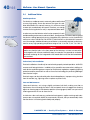
1
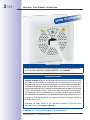
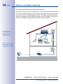
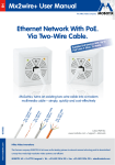
EN Mx2wire+ User Manual Security-Vision-Systems Ethernet Network With PoE. Via Two-Wire Cable. To ith Up vices W tts) e D d n sE Wa Supplie s 3 (Max. 13 s la C E Po www.mobotix.com e.g up ., Ca to t7 50 ca 0 m ble e.g up ., po to we 30 r c 0 m ab le e.g up ., be to ll w 30 ire 0m e.g up ., co to axi 50 al 0 m ca ble 60.188_EN_V3_04/2014 Mx2wire+ turns an existing two-wire cable into a modern multimedia cable – simply, quickly and cost-efficiently Latest PDF file: www.mobotix.com > Support > Manuals Innovations - Made in Germany The German company MOBOTIX AG is known as the leading pioneer in network camera technology and its decentralized concept has made high-resolution video systems cost efficient. MOBOTIX AG • D-67722 Langmeil • Tel: +49-6302-9816-103 • Fax: +49-6302-9816-190 • [email protected] 2/44 Mx2wire+ User Manual: Introduction MANY GER ADE IN M MOBOTIX Seminars MOBOTIX offers inexpensive seminars that include workshops and practical exercises. For more information, visit www.mobotix.com > Seminars. Copyright Information All rights reserved. MOBOTIX, the MX logo, MxControlCenter, MxEasy and MxPEG are trademarks of MOBOTIX AG registered in the European Union, the U.S.A., and other countries. Microsoft, Windows and Windows Server are registered trademarks of Microsoft Corporation. Apple, the Apple logo, Macintosh, OS X, iOS, Bonjour, the Bonjour logo, the Bonjour icon, iPod and iTunes are trademarks of Apple Inc. registered in the U.S.A. and other countries. iPhone, iPad, iPad mini and iPod touch are Apple Inc. trademarks. Linux is a trademark of Linus Torvalds. All other marks and names mentioned herein are trademarks or registered trademarks of the respective owners. Copyright © 1999-2014 MOBOTIX AG, Langmeil, Germany. Information subject to change without notice! Download the latest version of this and other manuals as PDF files from www.mobotix.com > Support > Manuals. © MOBOTIX AG • Security Vision Systems • Made in Germany www.mobotix.com • [email protected] 3/44 Contents 1Introduction 6 1.1 Two-Wire Cables 7 1.2 Automatic Device Configuration 8 1.3 Application Examples 9 1.4 Overview: Performance Data 15 2Installation 20 2.1 Delivered Parts and Components 20 2.2 Housing and Connectors 21 2.3 Mounting Instructions 22 2.4 Preparing the Installation 23 2.5 Set the PoE Class of the Power Supply 27 2.6 Installation Using Cavity or In-Wall Socket 28 2.7 Installation with On-Wall Socket 30 3Operation 32 3.1 Transfer of Data and Power 32 3.2 Connection Options (Positioning of PoE Power Supply) 35 3.3 LED Signaling: Operating Statuses and Error Messages 38 3.4 Additional Notes 40 Manufacturer43 Mx2wire+ transfers data as well as power according to the PoE standard! Mx2wire+ uses an efficient encryption method (128-bit AES), unlike a standard network cable! Mx2wire+ does not require a separate power connection! Mx2wire+ uses existing telephone, power or antenna cables and therefore eliminates the enormous amount of time and effort normally required for cabling! Mx2wire+ turns an existing two-wire cable into a modern multimedia cable – simply, quickly and cost-effectively! Mx2wire+ is a quality MOBOTIX product made in Germany: 100 percent guaranteed! © MOBOTIX AG • Security Vision Systems • Made in Germany www.mobotix.com • [email protected] 4/44 Mx2wire+ User Manual: Introduction FOREWORD Dear MOBOTIX customer, Congratulations on your decision to select an innovative quality product ‘Made in Germany’! The 2nd-generation Mx2wire+ media converter (available as of 11/2011) allows you to transform a two-wire cable into a network cable including PoE power supply with a maximum power output of 13 watts (PoE class 3) in just a few minutes. Minimal installation effort is required to replace an analog telephone with an IP telephone, for instance. Or you can use the existing coaxial cable of an old analog camera to replace this camera with a modern MOBOTIX HiRes camera with up to a thirty times higher image resolution. Please make sure that all components are included as listed in the overview in Section 2.1. The manual then gives you a brief overview of the innovative product concept and presents you with practical ways to use the Mx2wire+ media converter. This is followed by all the information you need to install and operate the device. If you have any questions, you can contact our support staff at [email protected] from Monday to Friday, 8 a.m. to 6 p.m. (German time). Support is free of charge (not including your connection costs). We would like to thank you for your trust and wish you all the best with your MOBOTIX product! Your MOBOTIX Team Important Notes Never Disconnect the Mx2wire+ Sets The two identical Mx2wire+ units can only be used together in a prepackaged set. The units are paired to one another with the same seven-digit network ID. The network ID can be found on the white sticker in the upper left corner on the front side of the circuit board (behind the front panel with the RJ45 port). If one Mx2wire+ unit is replaced with a unit from another set, a software tool (available soon from MOBOTIX) needs to be used to change the network ID manually. Electrical Installation Electrical systems and equipment may only be set up, changed and maintained by a qualified electrician (or under the management and supervision of a qualified electrician) in accordance with electrotechnical regulations. Data Transfer Rates and Cable Lengths We have tested the product very carefully and, instead of specifying non-recurrent peak values, we only provide the important net data rate, which was measured over a long period of time. However, we can provide no guarantee of possible cable lengths, data rates and power transmission, as various physical factors are not within the area of responsibility of MOBOTIX (sources of interference such as machines or power cables, the condition and quality of the cables used, etc.). The nominal data rate, connection length and power transmission can only be individually tested and determined at the place of installation. © MOBOTIX AG • Security Vision Systems • Made in Germany www.mobotix.com • [email protected] 5/44 Contents Enjoy the Unique Advantages Offered by Mx2wire+ In many houses television, telephone and other distribution networks based on two-wire cables are already installed, but no longer used. For example, a previously cable-bound telephone system may have been replaced by a wireless one. Existing, unused cables can now be quickly connected to Mx2wire+ and transformed into network connections throughout an entire building.An old analog camera can also be instantly exchanged for a digital, high-resolution MOBOTIX network camera without the need for any recabling and with all the associated benefits. New Possibilities, More Convenience: • Ethernet and PoE data transfer using a two-wire cable • Simple connection of 10/100 Mbps Ethernet end devices (e.g., IP camera, IP telephone) • Power supply for Mx2wire+ and end device via PoE/PoE+ or 48–57 V DC, 600 mA • Connected end devices are supplied with up to 13 watts via PoE (PoE class 3) • Maximum data transfer range of 500 m and data rate of up to 50 Mbps (depending on distance) • No need for expensive and time-consuming installation of network cables • Perfect for wireless communication is not possible (due to distance to sender, thickness of walls, etc.) • Network extension, including PoE, by connecting a Cat7 cable of up to 500 m in length as a two-wire cable • Simple installation in standard sockets (surface- or flush-mounted) • Two LEDs display current connection and supply statuses • Developed, produced and patented by MOBOTIX Germany Office with several PoE end devices © MOBOTIX AG • Security Vision Systems • Made in Germany www.mobotix.com • [email protected] Home with network connection 6/44 Mx2wire+ User Manual: Introduction 1 INTRODUCTION Using the Mx2wire+ system from MOBOTIX, an Ethernet network with PoE can be established using existing cables up to 500 m. This means that you can utilize a two-wire cable that is no longer in use (analog telephone line, antenna cable or bell wire, for instance) to connect a 10/100 Mbps Ethernet device such as a PC, Wi-Fi, IP camera, IP telephone or IP door station without having to lay any new cables or implement any other constructional measures. An (identical) Mx2wire+ unit is required at both ends of the cable, and it automatically configures itself as either the sender or the receiver (MOBOTIX patent). Mx2wire+ Mx2wire+ Two-wire cable Data & power max. 10 m PoE out max. 13 W max. 500 m Mx2wire+ requires a PoE power supply via a standard PoE switch (class 0, IEEE 802.3af or class 4, IEEE 802.3at) for operation PoE switch/injector IEEE 802.3af/at TCP/IP PoE If no PoE switch is used, power can also be supplied using the NPA-PoE set from MOBOTIX or a DC power supply unit (Section 3.2) The significant benefit of Mx2wire+ is that, in addition to data, the power to operate PoE end devices (Power-over-Ethernet according to the IEEE 802.3af standard, a MOBOTIX network camera, for example) can also be transferred via the two-wire cable. Mx2wire+ is delivered via PoE from a network cable that feeds in. The connected end devices are supplied with up to 13 watts via PoE. Mx2wire+ does not therefore require its own power supply, as the network distributor (switch) typically supplies power over the data cables (PoE) so that the two Mx2wire+ units as well as the standard PoE end device are supplied. Mx2wire+ is delivered in the standard wall outlet frame in different designs, however, it can also be used with the available on-wall socket that is included. Note Mx2wire+ takes over the cable function for network and PoE, therefore, the cable cannot be simultaneously used for power, analog telephone or antenna connection anymore! © MOBOTIX AG • Security-Vision-Systems • Made in Germany www.mobotix.com • [email protected] Two-Wire Cables 1.1 7/44 Two-Wire Cables A two-wire cable is usually a two-wire copper cable whose two wires are twisted together (twisted pair). A classic two-wire cable is an analog telephone wire with a wire diameter of 0.8 mm, which, in terms of quality (according to the ISO/IEC 11801 standard), corresponds to a category 1 cable for voice transmission. MX2wire+ can also be operated using untwisted cables that have at least two wires forming a physical connection between the two Mx2wire+ units. Please note that the quality, length and diameter of the two-wire cable used all have an influence on the transfer of data and the PoE output (see Section 1.4). Antenna or Coaxial Cable (e.g., for an Analog Camera) • Cable type: RG according to MIL-C-17 (coaxial cable) • An analog camera can be easily exchanged for an IP camera • Interference-free thanks to closed systems and cable shielding • Range (at 40 Mbps): 500 m Analog Telephone Line or Bell Wire (e.g., for an IP Telephone) • Cable type: JY, A2Y and YR (telephone and low-voltage cable) • Very good availability in buildings • Core diameter 0.6 to 0.8 mm • Range (at 40 Mbps): 300 m Power Line (Should No Longer Be Live) • Cable type: NY (installation cable) • Widespread availability of cables • Cables must be disconnected from the power supply! • Wire cross-section max. 2.5 mm2 • Range (at 40 Mbps): 300 m Ethernet Installation Cable (for Extending the Network) • Cable type: Cat7 (S/FTP, 4x2xAWG 23, 1000 MHz) • Long range data and power transmission • Range (at 40 Mbps): 500 m © MOBOTIX AG • Security-Vision-Systems • Made in Germany www.mobotix.com • [email protected] By correctly combining or twisting additionally available wires to form two wires or cables, the transmission line for data and power can be considerably increased 8/44 Mx2wire+ User Manual: Introduction 1.2 Automatic Device Configuration When data and power are sent via the two-wire cable, a (feeding) Mx2wire+ unit functions as the sender while the other unit functions as the (data) receiver. The sender is the Mx2wire+ unit that is supplied directly from the PoE switch. Communication between the units is possible in both directions, as the ‘sender’ and ‘receiver’ roles always configure themselves automatically. Sender/Receiver Mx2wire+ Transmitting and receiving in both directions Mx2wire+ Two-wire cable Power can be supplied from both sides, even simultaneously max. 500 m • PoE out: max. 13 Watt Sender/Receiver Sender/Receiver Note Greater data security: The Mx2wire+ media converter uses an efficient encryption method (128-bit AES), unlike a standard network cable. © MOBOTIX AG • Security-Vision-Systems • Made in Germany www.mobotix.com • [email protected] 9/44 Application Examples 1.3 Application Examples A) Exchanging an Analog Camera for an IP Camera Anyone who would like to benefit from the numerous cost and technological advantages of a high-resolution MOBOTIX IP camera, but has an analog camera already installed, can continue to conveniently use the camera's coaxial cable as a two-wire cable. A standard power supply (48 V DC, 600 mA) whose voltage outputs are connected to an Mx2wire+ unit is used for the PoE power supply for the IP camera. The existing Wi-Fi DSL router connected to the second Mx2wire+ unit is used for remote camera access via the Internet and the Dynamic Domain Name System (DynDNS) entry. Only the analog camera needs to be replaced with a HiRes camera. The coaxial cable and potentially even the analog camera's power supply unit can still be used Power supply unit 48-57 V DC Old coaxial cable Data and power Remote camera access Wi-Fi router via the Internet © MOBOTIX AG • Security-Vision-Systems • Made in Germany www.mobotix.com • [email protected] Coaxial cables are ideallysuited for longer distances(up to 500 m) 10/44 Mx2wire+ User Manual: Introduction B) Connecting a PC to the Internet in a Separate Apartment An Internet connection exists on the ground floor of a house and a PC in a separate apartment within the house is supposed to be added. The concrete walls and/or distance make a network extension via WLAN impossible. In this example, Mx2wire+ is simply connected to the two wires of the analog telephone line that is no longer being used. All that Mx2wire+ requires to supply power to the end device (PC) and for its own consumption is a PoE switch or injector. Home DSL router Mx2wire+ eliminates the enormous amount of time and cost normally required for cabling simply by reusing the old telephone line as a network cable Separate apartment PoE switch/injector IEEE 802.3af/at Old telephone line DSL, data and power © MOBOTIX AG • Security-Vision-Systems • Made in Germany www.mobotix.com • [email protected] 11/44 Application Examples C) Connecting a Wi-Fi Router to a Remote DSL Connection DSL, data and power Old telephone line The DSL connection is on the ground floor. Several PCs located two floors higher are to be connected to this. WLAN cannot be used over the entire distance. The distance from the router on the ground floor to the second floor can be bridged by Mx2wire+ and an analog telephone line, for example. By connecting a Wi-Fi router to the Mx2wire+ unit on the second floor, the PCs there can now access the Internet via Wi-Fi. Power is supplied to the Wi-Fi router via the Mx2wire+ devices (max. 13 W) Wi-Fi router DSL router PoE switch/injector IEEE 802.3af © MOBOTIX AG • Security-Vision-Systems • Made in Germany www.mobotix.com • [email protected] The concrete ceiling makes it impossible to set up a WLAN connection to the top floor 12/44 Mx2wire+ User Manual: Introduction D) Connecting an IP Camera to a PC Mx2wire+ allows an old power line to be used to connect a modern, PoE-supplied IP camera including audio/video and switch functions. A standard PoE switch/router or the compact MX-NPA-PoE set including crossover function (as shown here in the example) is used for the PoE power supply. A patch cable (at least Cat5) is used to connect the PC, which serves to control the camera, directly to the PoE switch. Home MX-NPA-PoE set Here, a two-wire cable, formerly used as a power connection, serves to connect an IP camera in a garage while keeping costs to a minimum No power supply is necessary for the camera in the garage Old power line Data and power Garage The MOBOTIX PoE injector is available as an accessory (MX-NPA-PoE set) MOBOTIX Injector for the PoE Power Supply (According to IEEE 802.3af) Mx2wire+ requires the correct power supply for all installations. Here, you can choose between a standard PoE/PoE+ switch/router, a power supply unit and the MX-NPA-PoE set that is available from MOBOTIX as an accessory. © MOBOTIX AG • Security-Vision-Systems • Made in Germany www.mobotix.com • [email protected] 13/44 Application Examples E) Replacing an Analog Telephone with an IP Video Phone DSL, data and power Old telephone line A DSL connection and a PC can be found on the ground floor. An analog telephone line extends upstairs from the ground floor. Mx2wire+ is used to transform the telephone line into a network cable that can transport data as well as power. The old telephones can easily be replaced with IP video phones that are also supplied with power from the PoE switch via Mx2wire+. IP video telephone (PoE supply) DSL router PoE switch/injector IEEE 802.3af/at IP video phone (PoE supply) © MOBOTIX AG • Security-Vision-Systems • Made in Germany www.mobotix.com • [email protected] No power connection is required for the Mx2wire+ device and IP telephone as up to 13 watts of power can be supplied via PoE 14/44 Mx2wire+ User Manual: Introduction F) Connecting Several Network End Devices Via Mx2wire+ An Internet connection exists on the ground floor. An office with various network devices (PCs, printers and IP video phones) is to be set up on the first floor. Mx2wire+ is connected to the two wires of the analog telephone line that is no longer used. All that Mx2wire+ requires to supply power to the IP telephone and for its own consumption is a PoE switch, to which the remaining network devices can also be directly connected. Mx2wire+ turns the former telephone line into a network cable for several end devices in the office DSL, data and power Old telephone line The PoE switch on the first floor serves to supply power to the Mx2wire+ device in the basement PoE switch/injector IEEE 802.3af/at DSL router © MOBOTIX AG • Security-Vision-Systems • Made in Germany www.mobotix.com • [email protected] 15/44 Overview: Performance Data 1.4 Overview: Performance Data The data rates shown in the tables are net data rates, also referred to as the payload, which are given in Mbps. In contrast to the gross data rates (including the data load for the operation of the system) that are usually provided when the performance data of DSL connections is specified, for instance, the amount of data shown here is the actual amount of data that is fully available to the end device operated on the Mx2wire+ receiver unit. As an example, a MOBOTIX network camera only requires a data rate of approximately 2.5 Mbps. Notes When long cables are used, voltage drops may make it impossible to supply end devices with power, so a separate power supply must be provided. In other words, the data range is generally greater than the maximum power transmission line. A separate voltage source (48–57 V DC, 600 mA) can be connected to both Mx2wire+ units. The maximum PoE power consumption for the end device is 13 watts (corresponding to PoE class 3). Only a network patch cable with a maximum length of typically ten meters should be connected directly to an Mx2wire+ unit in order to bridge the path to the next device (switch, router, PC, PoE injector or IP camera, for example). By correctly combining or twisting additionally available wires to form two wires or cables, the maximum transmission line for data and power can be considerably increased No provision is made by MOBOTIX for any further extension of the network, for example, by connecting a longer network cable to Mx2wire+. It is not possible to link more than two Mx2wire+ units. Overview: PoE Power Level Classes (IEEE 802.3af and 802.3at Standards) Class Max. Power Consumption 0 0.44 W–12.95 W 1 0.44 W–3.84 W 2 3.84 W–6.49 W for end device (max.) with power supply via PoE 3 6.49 W–12.95 W for end device (max.) with power supply via PoE or power supply unit (48–57 V DC) 4 12.95 W–25.5 W Class 4: IEEE 802.3at (PoE+) for Mx2wire+ This brief overview contains sample power output data that was obtained by MOBOTIX under real conditions and using standard benchmark test procedures. Refer to the following pages for more detailed information on power output. You will find tables with the net data rates and power output values depending on the type and length of the two-wire cable and the type of power supply (PoE class 3, class 4 or via the MOBOTIX NPA-PoE set, a particularly powerful class 3 PoE injector). © MOBOTIX AG • Security-Vision-Systems • Made in Germany www.mobotix.com • [email protected] Mx2wire+ supplies end devices with up to 13 W of power (up to class 3) 16/44 Mx2wire+ User Manual: Introduction Overview: Maximum power levels for Mx2wire+ (power supplied via: PoE+, IEEE 802.3at) Antenna or Coaxial Cable Thickness 0.6 mm inner core 50 m Data: 50 Mbps Power: 13 W Length of coaxial cable 100 m Data: 50 Mbps Power: 11 W 500 m Data: 45 Mbps Power: none Telephone Line and Bell Wire Thickness 50 m Length of telephone line/bell wire 100 m 200 m 0.6 mm Data: 50 Mbps Power: 13 W Data: 50 Mbps Power: 13 W Data: 50 Mbps Power: 8 W 0.8 mm Data: 50 Mbps Power: 13 W Data: 50 Mbps Power: 13 W Data: 50 Mbps Power: 13 W Installation Cable Thickness 1.5 mm2 50 m Data: 50 Mbps Power: 13 W Length of installation cable 100 m Data: 50 Mbps Power: 13 W 200 m Data: 50 Mbps Power: 13 W Extending the Range with Network Installation Cables Mx2wire+ can also be used to extend the range of an Ethernet connection that is limited to just 100 m in length (between the PoE switch and end device). For this purpose, a Cat7 installation cable is converted to a two-wire cable as follows: Open the four twisted wire pairs and remove approx. 7 mm of insulation from the ends. Then connect the four white wires and the four colored wires to one cable respectively and attach wire-end sleeves. Use two wire-end sleeves to connect to the two Mx2wire+ connectors Open the four twisted wire pairs Remove insulation from the ends of all eight wires Combine 4x white and 4x colored © MOBOTIX AG • Security-Vision-Systems • Made in Germany www.mobotix.com • [email protected] 17/44 Overview: Performance Data In conjunction with Mx2wire+, PoE class 3 power can be transmitted over a distance of 500 m at a data rate of approx. 45 Mbps. Type Cat7 Length of network installation cable (use of all four wire pairs) 200 m 300 m 500 m Data: 50 Mbps Power: 13 W Data: 50 Mbps Power: 13 W Data: 45 Mbps Power: 12 W Due to physical constraints, cables exceeding a certain length can still transfer data but not power. When installations have no PoE-supplied end devices (PCs, for example), the range of the two-wire cable may increase significantly, provided that low data rates are sufficient for the application. Note on Data Transfer Rates and Cable Lengths We have tested the product very carefully and, instead of specifying non-recurrent peak values, we only provide the important net data rate, which was measured over a long period of time. However, we can provide NO guarantee of possible cable lengths, data rates and power transmission, since various physical factors are not within the area of responsibility of MOBOTIX (sources of interference such as machines or power cables, the condition and quality of the cables used, etc.). The nominal data rate, connection length and power transmission can only be individually tested and determined at the place of installation. © MOBOTIX AG • Security-Vision-Systems • Made in Germany www.mobotix.com • [email protected] 18/44 Mx2wire+ User Manual: Introduction Table of Net Data Rates and Power Output PoE power level classes: class 0: 0.44–12.95 W class 1: 0.44–3.84 W class 2: 3.84–6.49 W class 3: 6.49–12.95 W 50 100 200 3 300 400 500 Data (in Mbps) 50 50 50 4 50 50 45 Power in W (PoE) 6.5 4.5 0 0 6.5 1.5 5.5 5 0 7 5 3 2 Power in W (PoE+) 13 11 6 3 1.5 0 Data (in Mbps) 50 50 50 40 0 0 7 6.5 3 1 0 0 Cable Length (in Meters) 1 Coaxial 2 Power in W (NPA) Bell wire 0.6 mm Bell wire 0.8 mm NYM 1.5 mm2 Cat7 (4 pairs) Power in W (PoE) Power in W (NPA) 7 7 6 5.5 0 0 Power in W (PoE+) 13 13 8 5 0 0 Data (in Mbps) 50 50 50 40 0 0 Power in W (PoE) 7 7 6 3.5 0 0 Power in W (NPA) 7 7 7 6.5 0 0 Power in W (PoE+) 0 Data (in Mbps) 13 13 13 10 0 0 50 50 50 40 0 0 Power in W (PoE) 7 7 7 7 0 0 Power in W (NPA) 7.5 7.5 7 7 0 0 Power in W (PoE+) 13 13 13 13 0 0 Data (in Mbps) 45 50 50 50 50 50 Power in W (PoE) 7 7 7 6.5 6 6 Power in W (NPA) 7.5 7.5 7 7 7 6.5 Power in W (PoE+) 13 13 13 13 13 12 Reader’s guide to the table: When upgrading a 1 coaxial cable to a two-wire cable with the 2 MOBOTIX NPA-PoE set to supply power using a cable length of 3 300 meters, you can achive a net data rate of 4 50 Mbps. The connected PoE end device (for example, a MOBOTIX IP camera) is continuously supplied with 5 five watts of power. © MOBOTIX AG • Security-Vision-Systems • Made in Germany www.mobotix.com • [email protected] 19/44 Overview: Performance Data Net Data Rates (in Mbps) Mbps 60  Net data rate (that can be effectively used by the end device) 50 Coaxial Bell wire 0.6 mm Bell wire 0.8 mm NYM 1.5 mm2 Cat7 (four pairs) 40 30 20 10 0 50 100 200 300 400 500 m Power Output with PoE Power Supply (in Watts) Watts 12  Power supply: PoE according to IEEE 802.3af 10 Coaxial Bell wire 0.6 mm Bell wire 0.8 mm NYM 1.5 mm2 Cat7 (four pairs) 8 6 4 2 0 50 100 200 300 400 500 m Power Output with NPA-PoE Power Supply (in Watts) Watts 12  Power supply: MOBOTIX NPA-PoE set 10 Coaxial Bell wire 0.6 mm Bell wire 0.8 mm NYM 1.5 mm2 Cat7 (four pairs) 8 6 4 2 0 50 100 200 300 400 500 m Power Output with PoE+ Power Supply (in Watts) Watts 12  Power supply: PoE+ according to IEEE 802.3at or DC power supply unit (48–57 V, 600 mA) 10 Coaxial Bell wire 0.6 mm Bell wire 0.8 mm NYM 1.5 mm2 Cat7 (four pairs) 8 6 4 2 0 50 100 200 300 © MOBOTIX AG • Security-Vision-Systems • Made in Germany www.mobotix.com • [email protected] 400 500 m 20/44 Mx2wire+ User Manual: Installation 2 INSTALLATION 2.1 Delivered Parts and Components 1.7 1.6 1.8 Components of an Mx2wire+ unit (each set contains two units) 1.5 1.9 1.4 1.1 1.3 Items 1.1, 1.2 and 1.3 are joined together when delivered and must be separated before the installation 1.2 Item Number Part Name 1.1 2 Mx2wire+ housing and circuit board including stainless steel screw (2x11 mm) 1.2 2 Front panel including stainless steel screw (M3x12 mm) 1.3 6 White frames: 2 concave, 2 convex, and 2 flat 1.4 8 Self-tapping stainless steel screws (3x10 mm) 1.5 2 Torx wrench for Torx screws 1.6 8 Torx screws (M3, 5x40 mm), washers (3.5 mm), screw anchors 1.7 2 White on-wall socket, height of 35 mm, including 8-wire plug 1.8 4 Two plugs for 3-5 mm cables and two plugs for 5-7 mm cables (alternative to 8-wire plug) 1.9 2 Cavity socket © MOBOTIX AG • Security-Vision-Systems • Made in Germany www.mobotix.com • [email protected] 21/44 Housing and Connectors 2.2 Housing and Connectors The Mx2wire+ media converter is a set of two Mx2wire+ units, each consisting of a circuit board and housing, front panel, frames, in-wall or on-wall socket and assembly parts. Connectors • Front panel: Network RJ45 (Ethernet network including PoE supply) • Rear panel: Two-wire (connectors 1 and 2) and 48–57 V DC (connectors 3 and 4) LED 1 green (power) LED 2 orange (data) For LED signaling, see Section 3.3 RJ45 network connection Optional 48–57 V DC power supply Mx2wire+ two-wire connection 4 3 2 1 Only connectors 1 and 2 may be used for the two-wire connection. Connectors 3 and 4 are only used for connecting a separate power supply unit if there is no other PoE supply (switch/injector) available in the system or its power level is no longer sufficient to supply power to the end devices. © MOBOTIX AG • Security-Vision-Systems • Made in Germany www.mobotix.com • [email protected] The terminals of Mx2wire+ are designed for wire cross-sections of between 0.13 mm2 and 2.5 mm2 (solid wire) 22/44 Mx2wire+ User Manual: Installation 2.3 Mounting Instructions Please check that all components supplied with Mx2wire+ are present in the original packaging (see Section 2.1). In order to avoid damaging the device, you should always use the assembly parts provided. In addition to the Mx2wire+ media converter, the following tools are required for installation: • Philips screw driver • Power drill for screw anchor holes (drill size: 5) • Hole saw (68 mm) for supplied cavity socket • MOBOTIX drilling template (at the end of this manual) • Scissors to cut out the drilling template • Pen to mark the drill holes • Tools for preparing the two-wire cable (such as a cable stripper) • Screwdriver for cable anchors on the housing (such as a voltage tester) Never connect or handle live cables (e.g., 230 V power supply) on your own; always have a trained electrician do the installation Solid Concrete or Stone Wall, Minimum Thickness: 60 mm Use a in-wall socket and, if required, the supplied screw anchors und Torx screws for the installation. Cavity Wall (e.g., Plasterboard, 7 mm to 35 mm) Use the supplied cavity socket for the installation. Note In principle, an Mx2wire+ unit can be installed using the on-wall socket, a standard in-wall socket or a cavity socket (see Section 2.4 to 2.6). On-wall socket Standard in-wall socket Cavity socket (wood or plasterboard, for example) © MOBOTIX AG • Security-Vision-Systems • Made in Germany www.mobotix.com • [email protected] 23/44 Preparing the Installation 2.4 Preparing the Installation Determining the Installation Location The Mx2wire+ media converter must always be installed indoors on a wall or ceiling protected from weather and moisture. If in doubt, use the normal functional conditions of a standard socket without cover as a reference. Note Do not block or cover the holes in the front panel (air circulation). Mounting Options In addition to an on-wall mounting using the supplied on-wall socket, you can also choose to install Mx2wire+ using a standard in-wall socket or a cavity socket (for wood or plasterboard, for example). Included in the delivery is a cavity socket of very high quality with soft rubber gaskets on the rear that need to be punctured by the two wires that feed in. The tight seal provided here is far superior to that offered by standard cavity sockets without this feature. Existing standard sockets are mostly used Preparing and Testing the Two-Wire Cable If no two-wire connection exists, the first task is to lay a suitable two-wire cable. Generally, existing cables are used with Mx2wire+. When cables have more than two wires, make sure (color coding) that the same cable pair is used for both Mx2wire+ units (see figure). Approximately 5 mm of insulation must be stripped from both ends of the two-wire cable. Prepared coaxial cable No multi-core cables allowed (unless equipped with wire-end sleeves) Before installing the two Mx2wire+ units, test the cable connection to ensure that it is functioning properly (if necessary, draw up a test chart). Due to their design, coaxial cables and Ethernet cables (Cat7) are particularly suited for longer distances. © MOBOTIX AG • Security-Vision-Systems • Made in Germany www.mobotix.com • [email protected] 24/44 Mx2wire+ User Manual: Installation Preparing the Standard In-Wall Socket In general, the existing in-wall socket of the two-wire cable continues to be used for Mx2wire+. Otherwise, an in-wall socket must be fitted first. Make sure that the socket you use is as flush with the wall as possible, so that you can install the respective Mx2wire+ unit properly. Make sure that the socket and Mx2wire+ unit are aligned correctly in the wall. After connecting the two-wire cable, there are two ways to attach the Mx2wire+ circuit board to the in-wall socket: 1. Secure the Mx2wire+ housing and circuit board directly to the socket by fastening two small screws (item 1.4) in the 12 o'clock and 6 o'clock positions. However, this requires that the socket is properly aligned in the wall. Thanks to the elongated shape of the screw holes, it is possible to make small adjustments to the left and to the right when tightening the screws. Attached to the socket using two screws (item 1.4) 2. Use four or two (diagonally opposite one another) Torx screws/screw anchors (item 1.6) to tightly screw the Mx2wire+ housing and circuit board to the wall. We recommend this procedure if the installed in-wall socket is not properly aligned or is not flush with the wall. Otherwise, the Mx2wire+ unit could easily be pulled out together with the in-wall socket. Attached to the wall using two or four 4 Torx screws/screw anchors (item 1.6) Two screws, diagonally opposite one another, are normally sufficient. Caution Do not drill through live cables in the wall. © MOBOTIX AG • Security-Vision-Systems • Made in Germany www.mobotix.com • [email protected] 25/44 Preparing the Installation Caution Please avoid all direct contact with the circuit board (ESD) and only touch the edge of the board in order to prevent damage arising now or later and to avoid reducing the service life. The in-wall socket used for Mx2wire+ must have an installation depth of at least 30 mm and should be flush with the wall. min. 30 mm Note If you do not have a standard in-wall socket available, you can also use the supplied cavity socket for flush mounting. © MOBOTIX AG • Security-Vision-Systems • Made in Germany www.mobotix.com • [email protected] 26/44 Mx2wire+ User Manual: Installation Preparing the Cavity Socket Mx2wire+ can also be mounted to cavity walls (e.g., plasterboard up to a thickness of 35 mm) using either the supplied cavity socket or an existing socket. Push the cavity socket into the prepared drill hole (68 mm) in the cavity wall and secure it by tightening the clamp screws. The metal claws automatically pop out and clamp the cavity socket firmly to the rear of the wall. After connecting the two-wire cable, secure the Mx2wire+ housing and circuit board directly to the cavity socket by fastening two small screws (item 1.4) in the 12 o'clock and 6 o'clock positions. This requires that the socket is properly installed in the wall. Attached to the socket using two screws (item 1.4) Note The supplied cavity socket ensures a convenient and secure installation along with a very tight seal thanks to its soft rubber covers (for two-wire cables). When the screws are tightened, the metal claws automatically pop out and clamp the socket to the cavity wall (made of wood or plasterboard, for example) © MOBOTIX AG • Security-Vision-Systems • Made in Germany www.mobotix.com • [email protected] Set the PoE Class of the Power Supply 27/44 2.5 Set the PoE Class of the Power Supply Mx2wire+ always logs on as a PoE class 0 device (0.44–12.95 W) and supplies the connected end device with up to 7.5 W of power (up to PoE class 2), depending on cable length and type, when using a PoE class 0 injector/switch. End devices can be supplied with up to 13 W of power (up to PoE class 3) when using a more powerful PoE+ class 4 injector/switch (12.95–25.5 W). It is possible to achieve this value if a power supply unit with the specification 48–57 V DC, 600 mA is used for the power supply. Important When connecting a PoE+ class 4 injector/switch (12.95–25.5 W), the PoE rotary switch on the Mx2wire+ circuit board connected to the injector/switch needs to be switched to 4 (from 3) in order to make use of the full potential of PoE+. The standard setting 3 is selected for power supply: • via PoE injector/switch (class 0 or 3, max. 12.95 W) • via MOBOTIX NPA-PoE set • via power supply unit (48–57 V DC, 600 mA) Changing the PoE Class (From 3 to 4): 1. Loosen the screws in the front panels (item 1.2) and lift the panels forwards. 2. Using a small screwdriver, switch the rotary switch on the Mx2wire+ connected to the injector/switch from position 3 to position 4 (see figure). This setting corresponds to the PoE classes 3 and 4 of the injector/ switch used. The PoE classes 1 and 2 are generally not selected because Mx2wire+ already requires 2 x 3 watts for its own consumption (PoE class 1 for each unit) and if a single class 1 or 2 injector/ switch is connected to the sender unit, there would be no power for the Mx2wire+ receiver unit or an end device. 3. The front panel does not need to be screwed back on until installation is complete (see the following pages). © MOBOTIX AG • Security-Vision-Systems • Made in Germany www.mobotix.com • [email protected] Class 3 (factory setting) Class 4 (PoE+ power supply) 28/44 Mx2wire+ User Manual: Installation 2.6 Installation Using Cavity or In-Wall Socket 1. Prepare the cavity or in-wall socket: see Section 2.4 Connectors 1 and 2 cannot be swapped (danger of overheating) 2. Two-wire cable to screw terminals 1 and 2: It is important that one cable is attached to the terminal with the same number on both Mx2wire+ units. The device can overheat if terminals 1 and 2 are swapped. 43 2 1 3. Outputs of power supply unit to screw terminals 3 and 4: If, instead of a PoE switch/injector, a DC power supply unit (48–57 V) is used to supply power, it is connected to one of the two Mx2wire+ units. See the description for alternative connection options in Section 3.2. The screw does not need to be removed completely from the front panel * If not already done (see Section 2.5) 4. Remove the front panel and frame*: In order to protect the Mx2wire+ circuit board, it is attached to the front panel and frame in the original packaging. In order to continue with the installation, however, you must first separate the housing and circuit board (item 1.1) from the panel and frame. Loosen the screw in the front panel (item 1.2) and lift the panel forwards. Now remove the attached frame from the circuit board. Please note that you will need the stainless steel screw in the front panel again later. © MOBOTIX AG • Security-Vision-Systems • Made in Germany www.mobotix.com • [email protected] Installation Using Cavity or In-Wall Socket 5. Insert the housing and circuit board into the socket: The two cable clamps on the rear of the housing are located at the top. When using a cavity socket (item 1.9), make sure you only use the stainless steel screws provided (item 1.6). Other (larger) screws could damage the circuit board. 29/44 The circuit board is attached directly to the socket using two screws (item 1.4.) (see left) or it is attached to the wall using the Torx screws (see page 24) 6. Attach the frame: Place the selected frame (item 1.3, concave, convex or flat) onto the circuit board and press down gently until it automatically snaps into place. MOBOTIX is printed on the bottom of the frame. MOBOTIX printed at the bottom 7. Insert the panel: Hook the front panel onto the frame, as shown in the figure, and then press it down. First hook panel on underneath, then click closed above 8. Screw the panel on tightly: Secure the front panel using the panel's stainless steel screw. Continue with Chapter 3, «Operation». © MOBOTIX AG • Security-Vision-Systems • Made in Germany www.mobotix.com • [email protected] 30/44 Mx2wire+ User Manual: Installation 2.7 Installation with On-Wall Socket Supplied cable plugs For cables of 3–5 mm 1. Prepare the on-wall socket: Use the supplied drilling template for the on-wall socket (fold-out at the end of this manual) to mark the precise position of the drill holes and the cable guide. Make sure that the alignment and position of the socket in relation to the two-wire cable are correct (TOP / OBEN arrow). For cables of 5–7 mm For cables with a maximum of eight wires The screw does not need to be removed completely from the front panel * If not already done (see Section 2.5) 2. Feed in the cables and screw on the on-wall socket: Feed the two-wire cable and the power supply unit (if used) through the opening provided that is sealed with a rubber plug. Use the 8-wire plug for the individual wires. The other plugs with only one opening are ideally suited to insulated, multi-wire cables of varying thickness. Now use the four Torx screws (item 1.6) to securely fasten the on-wall socket to the screw anchors or directly to the (wooden) surface. Please ensure that you only use the existing four drill holes of the on-wall socket. 3. Remove the front panel and frame*: In order to protect the Mx2wire+ circuit board, it is attached to the front panel and frame in the original packaging. In order to continue with the installation, however, you must first separate the housing and circuit board (item 1.1) from the panel and frame. Loosen the screw in the front panel (item 1.2) and lift the panel forwards. Now remove the attached frame from the circuit board. Please note that you will need the stainless steel screw in the front panel again later. © MOBOTIX AG • Security-Vision-Systems • Made in Germany www.mobotix.com • [email protected] 31/44 Installation with On-Wall Socket 4. Two-wire cable to screw terminals 1 and 2: It is important that one cable is attached to the terminal with the same number on both Mx2wire+ units. The device can overheat if terminals 1 and 2 are swapped. 5. Outputs of power supply unit to screw terminals 3 and 4: If, instead of a PoE switch/injector, a DC power supply unit (48–57 V) is used to supply power, it is connected to one of the two Mx2wire+ units. See the description for alternative connection options in Section 3.2. 6. Insert the housing and circuit board into the on-wall socket: The two cable clamps on the rear of the housing are located at the top. Attach the housing and circuit board to the on-wall socket by fastening the four stainless steel screws (item 1.4) in the four existing drill holes. 7. Attach the frame: Place the selected frame (item 1.3, concave, convex or flat) onto the circuit board and press down gently until it automatically snaps into place. MOBOTIX is printed on the bottom of the frame. 8. Insert the panel: Hook the front panel onto the frame, as shown in the figure, and then press it down. First hook panel on underneath, then click closed above 9. Screw the panel on tightly: Secure the front panel using the panel's stainless steel screw. Continue with Chapter 3, «Operation». © MOBOTIX AG • Security-Vision-Systems • Made in Germany www.mobotix.com • [email protected] Connectors 1 and 2 cannot be swapped (danger of overheating)  43 2 1 32/44 Application examples in Section 1.3 As a rule, no additional network device is required, as the end device can be supplied with up to 13 watts via a PoE power supply Mx2wire+ User Manual: Operation 3 OPERATION 3.1 Transfer of Data and Power As shown in Section 1.3, Mx2wire+ can be put to practical use as an Ethernet extension that includes the transport of Power-over-Ethernet in a wide range of private or commercial applications. In principle, Mx2wire+ can always be used to connect any 10/100 Mbps Ethernet device (such as a PC, Wi-Fi, IP camera, IP door station or IP telephone, for example). A Mx2wire+ media converter set (2 units) transfers data at a rate of up to 50 Mbps (depending on the cable cross-section and length) and power according to the PoE standard (maximum 13 watts). Suitable PoE end devices can be simultaneously supplied by this power supply directly via Mx2wire+ (e.g., MOBOTIX camera, MOBOTIX door station, etc.). Mx2wire+ Network Connection Using a Patch Cable Network devices (such as PCs, routers, camera and switches, for example) are connected to the front of the Mx2wire+ unit simply by inserting the Ethernet network cable (Cat5 patch cable or higher) into the standard RJ45 connector. Only patch cables with a maximum length of 10 m should be used Note Two Mx2wire+ units must always be used as a pair (as originally packed). These two paired units have the same network ID. The network ID is printed on a sticker located in the top left corner of the circuit board. © MOBOTIX AG • Security-Vision-Systems • Made in Germany www.mobotix.com • [email protected] 33/44 Transfer of Data and Power Mx2wire+ Power Supply (Own Consumption and End Device) It is important to consider the fact that the Mx2wire+ pair requires approx. 6 watts for its own consumption (3 watts for each Mx2wire+ unit) when making the choice of how to supply the Mx2wire+ pair and the end device connected to it (e.g., MOBOTIX camera). Power can be supplied via one of the two Mx2wire+ units or via both units at the same time (for long cable lengths). The MOBOTIX PoE injector is available as an accessory (MX-NPA-PoE set)  There are two basic options here: 1. Connection via PoE device (PoE injector, PoE switch or a combination router/PoE switch of classes 0 or 4) 2. Connection via an external power supply unit (48–57 V DC, 600 mA) PoE Power Level Classes (IEEE 802.3af and 802.3at Standards) Class Max. Power Consumption 0 0.44 W–12.95 W for Mx2wire+ 1 0.44 W–3.84 W 2 3.84 W–6.49 W for end device (max.) with power supply via PoE 3 6.49 W–12.95 W for end device (max.) with power supply via PoE or power supply unit (48–57 V DC) 4 12.95 W–25.5 W Class 4: IEEE 802.3at (PoE+) Mx2wire+ supplies end devices with up to 13 W of power (PoE class 3) Connecting a PoE-Supplied End Device (e.g., MOBOTIX Camera) It does not matter which of the two Mx2wire+ units is used to provide the PoE power supply when connecting a PoE end device to the Mx2wire+ media converter. Always ensure, however, that sufficient PoE power is supplied. Due to Mx2wire+'s own consumption, a maximum of 13 watts can ultimately be delivered to a PoE end device. Less than 5 watts of power is sufficient to connect and supply a modern MOBOTIX Q25M Hemispheric Camera with all its integrated functions (long-term recording to flash memory, audio, two-way communication, recording upon detection of movements in an image, convenient event searching, etc.) via the two-wire cable, for example. © MOBOTIX AG • Security-Vision-Systems • Made in Germany www.mobotix.com • [email protected] MOBOTIX Q25M Hemispheric camera – for more information, visit www.mobotix.com 34/44 Mx2wire+ User Manual: Operation Multiple Coexistent Mx2wire+ Units Mx2wire+ Mx2wire+ A The closer cables of different Mx2wire+ pairs lie to each other, the stronger is the mutual interference and the reduction of data rates A 50 m cable length (bell wire) Mx2wire+ Mx2wire+ Net data rate: 2 x 18 Mbps (–30%) B Mx2wire+ C B Attention: the more Mx2wire+ pairs are located close to each other (e.g., in the same cable or cable canal), the lower is the net data rate Mx2wire+ 50 m cable length (bell wire) C Net data rate: 1 x 50 Mbps Example: A 50-meter long four-wire cable (bell wire), of which two wires are used for each pair of Mx2wire+ units (A and B) The data rate is 18 Mbps for each Mx2wire+ pair (from A to A and from B to B). If only one pair is connected (from C to C), the net data rate of Mx2wire+ is 50 Mbps. The reduced data rate in this example is due to the cables interfering with each other. The network number is located in the top left corner of every Mx2wire+ circuit board  Normally, the two pairs act like a network hub, that is, the data transferred from A to A is also available on the two units of the data path from B to B. In order to prevent this, each couple of Mx2wire+ units is paired at the factory, which means that they have the same network number (network ID) and can therefore communicate with each other. Note Two Mx2wire+ units must always be used as a pair (as originally packed). The two paired units have the same network ID. The network ID is printed on a sticker located in the top left corner of the circuit board. © MOBOTIX AG • Security-Vision-Systems • Made in Germany www.mobotix.com • [email protected] 35/44 Connection Options (Positioning of PoE Power Supply) 3.2 Connection Options (Positioning of PoE Power Supply) PoE Power Supply Between Router and Mx2wire+ Unit . Mx2wire+ Mx2wire+ Side supplied with power Two-wire cable max. 500 m PoE out PoE switch/injector Mx2wire+ always requires a PoE power supply of at least 6 watts (own consumption) IEEE 802.3af/at Power for Mx2wire+ DSL router TCP/IP PoE By default, Mx2wire+ logs onto the switch as a PoE class 0 device (can be changed to class 4). PoE Power Supply Between Mx2wire+ Unit and PoE End Device (Such as a Camera) . Mx2wire+ Mx2wire+ Side supplied with power Two-wire cable Camera and Mx2wire+ are supplied separately by the PoE switch max. 500 m TCP/IP PoE DSL router PoE switch/injector IEEE 802.3af/at Power for Mx2wire+ Connecting to the DSL router without a power supply is only possible if PoE power is supplied to the other Mx2wire+ unit. © MOBOTIX AG • Security-Vision-Systems • Made in Germany www.mobotix.com • [email protected] 36/44 Mx2wire+ User Manual: Operation PoE Power Supplied to Both Mx2wire+ Units Simultaneously Mx2wire+ Mx2wire+ Side supplied with power Side supplied with power Two-wire cable (extra long) Cables exceeding a certain length can still transfer data but not power No more transfer via PoE DSL Router PoE switch/injector PoE switch/injector IEEE 802.3af/at IEEE 802.3af/at If the two-wire cable is not sufficient to supply the Mx2wire+ remote station with power due to its length, both sides can be supplied with power via PoE. PoE Power Supply Using the MOBOTIX PoE Injector (MX-NPA-PoE Set) Mx2wire+ Mx2wire+ Side supplied with power Two-wire cable PC/Power LAN/Power NPA-PoE-Set DSL router Data and power max. 10 m max. 500 m PoE out The NPA-PoE set (pictured here) or the weatherproof NPA box (not pictured here, available in 2012) are suited for standard PoE power supply according to IEEE 802.3af Camera TCP/IP PoE The blue NPA-PoE set, which is available as an accessory from MOBOTIX (MX-NPA-PoE set), can be used as an alternative to the standard PoE switch (IEEE 802.3af). © MOBOTIX AG • Security-Vision-Systems • Made in Germany www.mobotix.com • [email protected] Connection Options (Positioning of PoE Power Supply) Network Without PoE, Power Supply Through One Device Via Power Supply Unit Mx2wire+ Mx2wire+ Two-wire cable Two-wire PoE out max. 500 m 48-57 V DC Power supply unit DSL router The power required for Mx2wire+ and one PoE end device can be supplied by connecting an external power supply unit (48–57 V DC, 600 mA) to another Mx2wire+ unit (max. power output for end device: PoE class 3/13 W). The external power can also be supplied via the unit to which the PoE end device is connected in order to reduce unnecessary performance losses. Network Without PoE, Power Supply Through Both Devices Via Power Supply Unit Mx2wire+ Mx2wire+ Two-wire cable (extra long) 48-57 V DC Power supply unit Two-wire Two-wire PoE out No more transfer via PoE 48-57 V DC Power supply unit DSL router If the two-wire cable is not sufficient to supply the Mx2wire+ remote station with power due to its length, both Mx2wire+ units can be supplied with power via a power supply unit (48–57 V DC, 600 mA). © MOBOTIX AG • Security-Vision-Systems • Made in Germany www.mobotix.com • [email protected] 37/44 38/44 LED 1 green (power) LED 2 orange (data) Mx2wire+ User Manual: Operation 3.3 LED Signaling: Operating Statuses and Error Messages Each Mx2wire+ unit has two LEDs (green and orange), which provide information on the current functional status of the PoE power supply and the data traffic. The LEDs can either light up continuously (ON) or they can blink (FLASH). Sender LED 1 Receiver LED 2 LED 1 LED 2 Two-wire cable PoE switch/injector IEEE 802.3af/at End device (camera/PC) The sender is the Mx2wire+ unit that receives power from the switch, as data is transferred in both directions LED 1 – Sender LED 2 – Sender LED 1 – Receiver ON ON ON LED 2 – Receiver ON Power is supplied to the Mx2wire+ unit from the switch (PoE) Network connection to the switch (PoE) has been established Power is supplied to the Mx2wire+ unit via the twowire cable Network connection to the camera has been established FLASH FLASH FLASH FLASH Camera is receiving power (is connected) Data traffic present never Data is transferred to the receiver Overview: Operating Statuses 1 to 4 LED 1 – Sender LED 2 – Sender LED 1 – Receiver LED 2 – Receiver 1 FLASH ON ON ON 2 ON ON ON ON 3 FLASH FLASH ON FLASH 4 ON FLASH ON FLASH 1. Mx2wire+ and the end device (camera) both receive sufficient power from the PoE switch (green LEDs). A data connection from the end device to the PoE switch is established (orange LEDs), however, no data is currently being transferred. The blinking of the green LED (only) on the sender indicates that another PoE end device (camera) is being supplied with power in addition to Mx2wire+. © MOBOTIX AG • Security-Vision-Systems • Made in Germany www.mobotix.com • [email protected] 39/44 LED Signaling: Operating Statuses and Error Messages 2. Both Mx2wire+ units receive sufficient power from the PoE switch (green LEDs). A data connection from the end device (PC) to the PoE switch is established (orange LEDs), however, no data is currently being transferred. 3. The blinking of the orange LEDs on both units indicates that data is being transferred from the camera to the switch via Mx2wire+. 4. When the green LED on the sender lights up rather than blinks, this indicates that no PoE-supplied end device is in operation here. Overview: Error Messages 1 to 3 LED 1 – Sender LED 2 – Sender LED 1 – Receiver LED 2 – Receiver 1 ON ON ON OFF 2 ON ON OFF OFF 3 OFF OFF OFF OFF 1. Sender receives sufficient power from the PoE switch. A data connection to the PoE switch is established via Ethernet. Although sufficient power is being supplied to the receiver, no connection to the end device is established. Troubleshooting tip: Either the network cable between the receiver and the end device is not functioning properly (cable is defective or too long) or there is a problem with the end device. 2. Sender receives sufficient power from the PoE switch. A data connection to the PoE switch is established via Ethernet. Receiver is not functioning, as it is not receiving any power and can therefore not establish a connection to the end device. Troubleshooting tip: Either the two-wire connection is not functioning properly (interrupted or too long) or there is a problem with the receiver. 3. The sender itself does not receive any power from the switch and no data connection is established. This means that the receiver cannot function either. Troubleshooting tip: Either the network cable between the sender and the switch is not functioning properly (cable is defective or too long) or there is a problem with the switch (either not suitable for Mx2wire+ or faulty) or with the sender. © MOBOTIX AG • Security-Vision-Systems • Made in Germany www.mobotix.com • [email protected] 40/44 Mx2wire+ User Manual: Operation 3.4 Additional Notes Weatherproofness The Mx2wire+ media converter is extremely robust and finished to a very high quality. Due to the nature of the types of installation described in this manual, however, it is neither resistant to water jets nor absolutely dust-proof. Therefore, we strongly recommend using Mx2wire+ only in a protected indoor area. MOBOTIX wall mount with Q25 camera In order to ensure that Mx2wire+ also functions properly in harsh and demanding environments and out of doors, extra provisions must be made to improve the device's sealing (protective housing, integration of the Mx2wire+ unit in the MOBOTIX wall mount when a MOBOTIX D12/D14/D15, D22/D24/D25 or Q22/Q24/Q25 camera is used, for example). Additional heating or ventilation is not normally required, as Mx2wire+ features a very high operating temperature range of -30 °C to +50 °C (-22 °F to +122 °F). Caution Make sure that the holes in the front panel of the Mx2wire+ unit are not covered or stuck together with silicone or adhesive tape, for example. They provide air circulation and heat exchange for the integrated circuit board and ensure that the board does not overheat. Professional, Safe Installation Electrical installations should only be carried out by properly trained specialists. MOBOTIX recommends having Mx2wire+ installed only by specialists accustomed to installing network devices and having proper respect for the pertinent regulations regarding lightning protection and fire prevention as well as the current technology for preventing damages from electrical surges. Electrical surges can be induced by other electrical appliances, improper wiring, but also from the outside (e.g., lightning strikes to phone or power lines). Care and Maintenance Clean each Mx2wire+ unit using a slightly moistened soft cloth, making sure that no liquid enters the unit through the holes in the front panel. Never use aggressive cleaning agents or cleaning agents with abrasive particles (scouring agent). Make sure you instruct cleaning personnel on how to clean the set. As Mx2wire+ does not have any mechanical moving parts, regular servicing and maintenance are not required. MOBOTIX recommends, however, that you occasionally check that the device is functioning both reliably and properly. © MOBOTIX AG • Security-Vision-Systems • Made in Germany www.mobotix.com • [email protected] 41/44 Additional Notes Electromagnetic Compatibility (EMC) Electromagnetic compatibility encompasses all unintentional or intentional malfunctions of electrical or electronic equipment generated by electrical, magnetic or electromagnetic fields and processes, for example. This includes interference from currents and voltages. The proof and verification of immunity to interference and a sufficiently low level of electromagnetic interference are regulated by EMC directives and EMC standards. Mx2wire+ is built to be interference-proof The European EMC Directive defines electro-magnetic compatibility as ”the ability of a device, equipment or a system to function satisfactorily in its electromagnetic environment without introducing intolerable electromagnetic disturbances to anything in that environment.“ The Mx2wire+ media converter complies with the relevant EMC regulations for information technology devices (see the Declaration of Conformity on page 42). with s kind uct of it patibility d ro p om only so far, o-magnetic c ard (TÜV)! t and, o The firs tion of electr al Control B a ic n m h r c fi e n T co n Germa by the Special Mx2wire+ Versions for MOBOTIX IP Video Door Station When replacing a simple doorbell with a high-quality IP video door station, MOBOTIX offers a weatherproof backlit house number field lit by economical, long-lasting LEDs for its door station that integrates the Mx2wire+ unit in an outdoor model and contains a second corresponding unit for installation in the home. Mx2wire+ Module 2 For more information: www.mobotix.com > Products Two-wire cable Data and power PoE switch/ injector Info2wire Module 1 IEEE 802.3af/at Data and power © MOBOTIX AG • Security-Vision-Systems • Made in Germany www.mobotix.com • [email protected] 42/44 Mx2wire+ User Manual Notes © MOBOTIX AG • Security-Vision-Systems • Made in Germany www.mobotix.com • [email protected] 43/44 Manufacturer To demonstrate our confidence in the quality of our products, MOBOTIX cameras have been used to capture all images that appear in this manual. Manufacturer MOBOTIX AG Kaiserstrasse 67722 Langmeil Germany Phone: +49 6302 9816-103 Fax: +49 6302 9816-190 www.mobotix.com [email protected] Registration Office: Kaiserslautern Local Court Registration Number: HRB 3724 Tax Office: Worms-Kirchheimbolanden, Germany Tax Code: 44/676/0700/4 VAT ID: DE202203501 You can find the latest version of this and other documents (e.g., declarations of conformity) at www.mobotix.com in the Support section. Technical specifications subject to change without notice! © MOBOTIX AG • Security-Vision-Systems • Made in Germany www.mobotix.com • [email protected] EN Mx2wire+ User Manual Security-Vision-Systems Ethernet Network With PoE. Via Two-Wire Cable. To ith Up vices W tts) e D d n sE Wa Supplie s 3 (Max. 13 s la C E Po www.mobotix.com e.g up ., Ca to t7 50 ca 0 m ble e.g up ., po to we 30 r c 0 m ab le e.g up ., be to ll w 30 ire 0m e.g up ., co to axi 50 al 0 m ca ble 60.188_EN_V3_04/2014 Mx2wire+ turns an existing two-wire cable into a modern multimedia cable – simply, quickly and cost-efficiently Latest PDF file: www.mobotix.com > Support > Manuals Innovations - Made in Germany The German company MOBOTIX AG is known as the leading pioneer in network camera technology and its decentralized concept has made high-resolution video systems cost efficient. MOBOTIX AG • D-67722 Langmeil • Tel: +49-6302-9816-103 • Fax: +49-6302-9816-190 • [email protected]