1
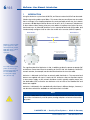
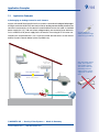
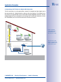
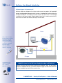
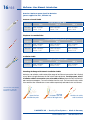
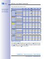
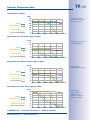
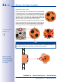
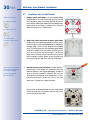
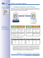
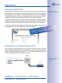
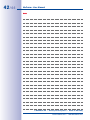
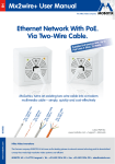
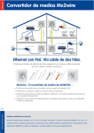
39/44 LED Signaling: Operating Statuses and Error Messages 2. Both Mx2wire+ units receive sufficient power from the PoE switch (green LEDs). A data connection from the end device (PC) to the PoE switch is established (orange LEDs), however, no data is currently being transferred. 3. The blinking of the orange LEDs on both units indicates that data is being transferred from the camera to the switch via Mx2wire+. 4. When the green LED on the sender lights up rather than blinks, this indicates that no PoE-supplied end device is in operation here. Overview: Error Messages 1 to 3 LED 1 – Sender LED 2 – Sender LED 1 – Receiver LED 2 – Receiver 1 ON ON ON OFF 2 ON ON OFF OFF 3 OFF OFF OFF OFF 1. Sender receives sufficient power from the PoE switch. A data connection to the PoE switch is established via Ethernet. Although sufficient power is being supplied to the receiver, no connection to the end device is established. Troubleshooting tip: Either the network cable between the receiver and the end device is not functioning properly (cable is defective or too long) or there is a problem with the end device. 2. Sender receives sufficient power from the PoE switch. A data connection to the PoE switch is established via Ethernet. Receiver is not functioning, as it is not receiving any power and can therefore not establish a connection to the end device. Troubleshooting tip: Either the two-wire connection is not functioning properly (interrupted or too long) or there is a problem with the receiver. 3. The sender itself does not receive any power from the switch and no data connection is established. This means that the receiver cannot function either. Troubleshooting tip: Either the network cable between the sender and the switch is not functioning properly (cable is defective or too long) or there is a problem with the switch (either not suitable for Mx2wire+ or faulty) or with the sender. © MOBOTIX AG • Security-Vision-Systems • Made in Germany www.mobotix.com • [email protected]