1
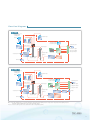
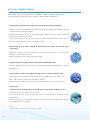
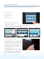
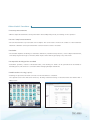
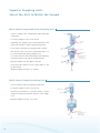
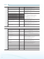
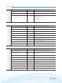
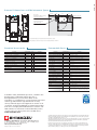
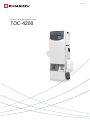
$&
On-Line Total Organic Carbon Analyzer
TOC - 4200
TOC-4200
Total Organic Carbon Analyzer
Highly Advanced On-Line T
TOC
OC A
Analyzer
nalyzer
p p licc a t i o n s
Excels in a Wide Range of A
Applications
Support for a
Wide Range of Samples
t Select
a sampling unit to match the
sample characteristics.
t Wide
measurement range from 5 mgC/L full-scale
to 20,000 mgC/L full-scale
Dilution function incorporated as standard.
Supports up to 50x dilution.
t High
sensitivity measurements from 0 to 1 mgC/L
(optional)
t Diverse
TOC measurements (NPOC, TC-IC*,
NPOC + POC* measurements), TN measurements*
*Optional
t Permits
making a multi-point calibration
curve from a single standard.
Diverse
Applications
t Wastewater
treatment plant influent
(upstream monitoring) and effluent
t Plant
water (washing water, cooling
water, recovered water, etc.)
t Boiler water, condensate
t Water and sewage (raw water,
treated
water), advanced treated wastewater
t Total
pollutant load control regulation
applications (organic pollution load)
Advanced
Operability
t Color LCD touch screen
t Supports data-storage devices.
Easy to
store measured values or measurement
conditions to USB memory
t Calendar scheduling setup
t Compatible with digital bus standard
t Web-based monitoring (optional)
It allows browsing of measured
values with a Web browser
by network.
Su pp or t f o r a W i d e R a n ge of S a m ple s
The most important demand for on-line TOC analyzers is stable operation.
The TOC-4200 incorporates Shimadzu’s accumulated technical expertise to provide stable operation across all
scenarios from pure water to heavily polluted water.
■ Range of sampling units to match a sample’s characteristics
t
Sampling units are available for applications from pure water to heavily polluted water.
t
Reduces instrument maintenance frequency.
t
Switch between measurement points for up to six flow lines. More economical since the need for multiple instruments is eliminated
■ Measurement ranges from 5 mgC/L full-scale to 20,000 mgC/L full-scale
An option can be attached to support high sensitivity measurements to 1 mgC/L full-scale. TC NPOC
t
TOC measurement by acidify and sparge TOC also know as non-purgeable organic carbon (NPOC) NPOC
t
TOC determination by difference between total carbon (TC) and inorganic carbon (IC)
TOC = TC - IC (requires option) TC
IC
t
TOC determination by addition method of NPOC and purgeable organic carbon (POC)
t
Support for 1 mgC/L full-scale high sensitivity measurements (optional) TC NPOC
t
Dilution function installed as standard. Supports up to 50x dilution.
TOC = NPOC + POC (requires option) NPOC POC
■ Permits making a multi-point calibration curve from a single standard.
t
Standard solutions for each calibration point can be made from a single
solution by using dilution function.
■ TN measurement option
Adding the TN measurement option permits total nitrogen (TN) measurements
(catalytic thermal decomposition – chemiluminescence detection). TN
Permits measurements from 1 mgN/L full-scale to 10,000 mgN/L full-scale.
■ Reliable sample injection system
t
A single unit performs sample intake, discharge, dilution and injection.
t
Automated sample acidification and sparging.
t
Highly reliable ceramic 8-port valve used to switch flow lines
Dilution water (also for rinsing)
Acid
Exhaust
(or IC/POC measurement)
Standard solution
for span calibration
Off-line sample
(or on-line sample)
Combustion tube
On-line sample inlet
Valve
4
Drain
Sparge gas
Flow Line Diagrams
TC NPOC
Multi Stream (Note 1)
Suspended Solids
Sampling Unit
Dilution water
Sample
(Note 2)
Acid
Homogenizer
Recording section
Recorder or printer
Standard
solution
USB memory stick
On-line sample
Sample injector
LCD
Off-line
sample
Transmission output
Data
processor
Keyboard
Compressed air inlet
Gas purifier,
electronic
flow rate
controller
Contact point output
Contact point input
Combustion tube
Furnace
Dehumidifier,
gas treatment
section
Sample pretreatment
/injection system
NDIR detector
Drain outlet
TC NPOC TN
Multi Stream (Note 1)
Suspended Solids
Sampling Unit
Dilution water
Sample
(Note 2)
Acid
Homogenizer
Recording section
Recorder or printer
Standard
solution
Sample injector
Off-line
sample
Compressed air inlet
LCD
Keyboard
Transmission output
Data
processor
Contact point output
Contact point input
Combustion tube
Gas purifier,
electronic
flow rate
controller
Chemiluminescence
gas analyzer
Furnace
Sample pretreatment
/injection system
Drain outlet
USB memory stick
On-line sample
Dehumidifier,
gas treatment
section
Ozone
Deactivator
Exhaust
NDIR detector
N
Note
1) FFor the
h sampling
li
section
section,
i
select
l
the
h multi
multi-stream
l i stream suspended
d d solids
lid sampling
li
unit
unit,
i the
h single
i l stream suspended
d d solids
lid sampling
li
unit
unit,
i the
h
backwash strainer sampling unit or the sample stream kit (option).
Note 2) For the recording section, select either the recorder or the printer (options).
TOC - 4200
Total Organic Carbon Analyzer
5
Di ver se A p p l i c a t i o n s
Measurement speed is the key feature of combustion catalytic oxidation TOC analyzers.
This characteristic can be exploited to support a diverse range of applications.
■ Wastewater treatment plant influent (upstream monitoring) and effluent
t
Measurements at a short measuring cycle (4 minutes minimum) rapidly capture dramatic changes
in organic matter or abnormal effluent.
t
The powerful oxidation capacity of a combustion-type analyzer can detect organic matter that
cannot be captured using a UV meter.
t
The short measuring cycle and powerful oxidation, combined with switching between up to six
flow lines, offer detailed monitoring of treatment plants.
■ Monitoring of river water sampled at water purification plants and treated water
(tap water)
t
Monitoring changes in river water quality due to rainfall and other factors to provide control
indicators for the treatment processes
t
Permits simultaneous monitoring of treated tap water.
■ Supports monitoring TOC removal rate based on EPA Regulations.
t
Calculates TOC removal rate based on the U.S.A EPA regulations (Part IV 40 CFR Part 9, 141 and
142, 1998). (*1)
■ Total pollutant load control regulation applications (organic pollution load)
t
Converting the measured TOC values allows applications to COD total volume control. (*2)
TOC → COD conversion functions are installed as standard.
t
Reading flow rate signals from a flow meter (*1) permits COD load conversion calculations.
■ Plant water
(washing water, cooling water, recovered water, boiler water, condensate, etc.)
t
Continuous monitoring of water used in a plant
t
Continuous monitoring of pure boiler water assists in the detection of anomalies, such as
damaged pipes.
t
The short measuring cycle (4 minutes minimum) of the combustion-type TOC analyzer achieves
more rapid detection of anomalies.
*1 Optional
*2 The TOC-COD conversion formula must be determined separately.
6
Exa mple of Installation for Upst re a m M o n i t o r i n g
River
Plant A
TOC (2)
TOC (1)
Plant B
Plant C
TOC (3)
Treatment
plant
Effluent
Cooling water
Rainwater
TOC (1) Prevents water pollution accidents through rapid detection of abnormal effluent.
TOC (2) Identifies the source of abnormal effluent to accelerate identification of the cause and prevention of recurrence (three-flow-line switching).
TOC (3) Monitoring of effluent not from the treatment plant
Process A
TOC (1)
TOC/ TN (2)
Public
water body
TOC/ TN (3)
(river, ocean)
Process B
Process C
Water
treatment
plant
Flow
meter
Effluent
TOC (5)
Cooling water
Rainwater
TOC (4)
Water
purification plant
Tap water
TOC (1) Monitoring of TOC values discharged from each process (three-flow-line switching)
TOC (2) Monitoring of inflow and outflow of water treatment plant (two-flow-line switching). Optimization control of treatment performance
(amount of aeration, etc.) at the water treatment plant
TOC (3) Monitoring of all effluent discharged from the enterprise. Load conversion calculations using flow rate signals input from a flow meter
TOC (4) Monitoring of abnormal values for cooling water and rainwater. Monitoring for abnormalities in the pipe system (two-flow-line switching)
TOC (5) Monitoring of water taken in the water purification plant. Monitoring for abnormalities in the tap water
TOC - 4200
Total Organic Carbon Analyzer
7
Ad v a nce d O p e r a b i l i t y
Because on-line analyzer operation is normally unmanned, ease of operation was emphasized.
■ Color LCD touch screen
t
Easy-to-view color LCD
t
Touch screen operation
Large buttons
Easy-to-operate touch screen
■ Intuitive setup, measurement start, and
measurement stop operations
t
When multiple flow lines are used, the measurement items, range and measuring cycle can be set separately for each
flow line to simplify the setup of complex scheduled operations.
■ Generous data storage capacity
t
The instrument internal memory can store 20,000 measured
values (equivalent to one year’s data at a 30-minute measuring
cycle), 100 calibration values (equivalent to weekly automatic
calibration over one year), and history of 100 alarms.
t
Six calibration curves can be saved for each measurement
type (TC, NPOC, IC*, POC*, and TN*) to simplify switching
between operation conditions.
t
USB port fitted as standard below the touch screen. Measured
values and measurement conditions can be saved to USB
memory. Measured results are saved as CSV files to simplify
the management and processing of large quantities of data.
*Optional
8
Other U se fu l Functions
■ Interrupt measurements
t
Off-line sample measurements can be performed in the standby time periods, even during on-line operation.
■ Control sample measurements
t
Periodic measurements of pre-selected control samples. This can be used to monitor the condition of the instrument.
Automatic calibration can be performed when a certain reference value is exceeded.
■ Calendar
t
The calendar simplifies scheduling for automatic calibration, instrument sleep function, control sample measurement,
and catalyst regeneration (up to 14 weeks). Batch inputs can be made by specifying a day of the week.
■ Compatible with digital bus standard
t
Instrument operation, readout of measured values, and checking for alarms can be performed via the RS-485 or
RS-232C (option). This function is convenient when managing multiple instruments.
■ Web-based monitoring (option)
t
Installing an optional board allows connection of the instrument to a network.
The optional board offers web-server functions, allowing real-time browsing of measured values and alarms with a
Web browser.
Calendar
Web-Based Monitoring
TOC - 4200
Total Organic Carbon Analyzer
9
Su per i or S a m p l i n g U n i t s
Sel ect t h e U n i t t o Ma t c h t he S a m ple
Multi-Stream Suspended Solids Sampling Unit
t Used
Sample
for samples with comparatively high suspended
solids levels.
Rinse
t It can treat samples in up to six flow lines.
t Separating
Sampling
Water
the sampling unit and pretreatment unit
reduces the number of parts requiring maintenance.
t Incorporates a homogenizer equipped with a strainer.
t The
Sample
Drain
Strainer
strainer is the most easily contaminated part. It is
Homogenizer
in contact with liquids during sampling only.
It is rinsed with rinse water immediately after sampling,
Sample
(to multi function
processing /
injection system)
Drain
reducing problems with slime and algae build-up.
t Required sample flow rate: Approx. 10 L/min
tA
Rinse
Water
Back flow
rinse
Drain Valve
low-flow (LF) model has been newly added to the
product lineup.
(Required sample flow rate: 1 to 2 L/min)
Drain
Multi-Stream Sample Switching Unit
t Used for samples with low suspended solids levels.
t It can treat samples in up to six flow lines.
t Assuming
Sample Drain
measurements of purified water, a water
sampler is installed to minimize exposure of the sample
Sample
to air.
t Required sample flow rate: 1 to 3 L/min
Drain Valve
Drain
Drain
10
Sample
(to multi function
processing /
injection system)
Backwash Strainer Sampling Unit
t This
unit is an adjustment bath used for samples with
Sample
(to multi function
processing /
injection system)
Air
low suspended solids levels.
t Offers automatic backwashing using air.
t A germicide installed in the air line suppresses blockage
of the strainer by microorganisms and growth of slime
and algae in the bath.
t Required sample flow rate: 1 to 3 L/min
Sample Drain
Sample
Single Stream Suspended Solids Sampling Unit
Germicide
t
Strainer
Used for samples with comparatively high suspended
solids levels.
t This
Sample
sampling unit is electrically driven. It requires no
air supply.
t After
Rinse Water
dirt is removed by the strainer, the homogenizer
pulverizes and homogenizes the suspended solids to
Homogenizer
obtain stable measured values.
t The
Sample
(to multi function
processing /
injection system)
strainer is the most easily contaminated part. It is
in contact with liquids during sampling only. It is rinsed
with rinse water immediately after sampling, reducing
Sample Drain
problems with slime and algae build-up.
tA
germicide is installed to effectively suppress slime
Pinch Valve
and algae growth.
t Required sample flow rate: 2 to 5 L/min
Drain
TOC - 4200
Total Organic Carbon Analyzer
11
O ptions
Sampling Unit
(Alternatives)
Part Name
Remarks
Multi-stream suspended solids sampling unit
638-93191-01 to 06
Sampling unit for samples with high suspended solids levels
Capable of switching between a maximum of 6 flow lines
Required sample flow rate: Approx. 10 L/min
Multi-stream suspended solids sampling unit LF
638-93191-11 to 16
Low-flow rate version of the multi-stream suspended solids sampling unit
Capable of switching between a maximum of 6 flow lines
Required sample flow rate: 1 to 2 L/min
Single stream suspended solids sampling unit
638-93186
Sampling unit for samples with high suspended solids levels
Single stream only
Required sample flow rate: 2 to 5 L/min
Backwash strainer sampling unit (with pump)
638-41507-21
Backwash strainer sampling unit (without pump)
638-41507-22
Backwash strainer sampling unit F (with pump)
638-41507-23
Backwash strainer sampling unit F (without pump)
638-41507-24
Backwash strainer sampling unit E (with pump)
638-41507-25
Backwash strainer sampling unit E (without pump)
638-41507-26
Backwash strainer sampling unit EF (with pump)
638-41507-27
Backwash strainer sampling unit EF (without pump)
638-41507-28
Multi-stream sample switching unit
638-93193-01 to 06
Sampling unit for measurement of comparatively clean samples
Capable of switching between a maximum of 6 flow lines
Required sample flow rate: 1 to 3 L/min
Sample stream kit
638-41582-01, 02
Sampling unit for measurement of comparatively clean samples
Single-flow-line (-01) and double-flow-line (-02) versions are available.
As the second flow line uses the off-line port, off-line measurement functions are
not available if the double-flow-line version (-02) is used.
Required sample flow rate: 1 to 3 L/min
Sample stream additional kit
638-41582-03
Expansion set to use the single-flow-line version of the sample stream kit as a
double-flow-line version
As the second stream uses the off-line port, off-line measurement functions are
not available if the double-flow-line version (-02) is used.
External I/O
External I/O
Sampling unit with automatic strainer backwashing using air
Single stream only
t
(with pump): Backwashing air is supplied from the internal pump to
the supply cylinder to reduce the air consumption.
t
(without pump): Backwashing air is supplied from carrier gas source.
t
“F”: With float sensor
This can detect if the sample water flow is interrupted.
t
”E”: No disinfection by germicide
Required sample flow rate: 1 to 3 L/min
Part Number
Remarks
Optional terminal (2) kit
638-79078
Terminal (2) expansion kit
Expanding contents Analog output: 2 channels
Contact input: 8 channels (For control 2 and 3 flow lines)
Optional terminal (3) kit
638-79079
Terminal (3) expansion kit
Required the option terminal (2) kit
Expanding contents Contact output: 26 channels
Contact input: 8 channels (For control 4 to 6 flow lines)
Optional terminal (2) (3) kit
638-79080
The kit for expanding Option terminal (2) kit and Option terminal (3) kit
simultaneously
Analog output board
638-79084
Each set offers two analog outputs.
Required for five or more outputs.
Up to four sets can be added (making 12 outputs maximum).
Requires the PCB fixing bracket, terminal (638-84218),
and optional terminal (2) kit (638-79078).
(Isolated outputs, load resistance: 500 Ω max.)
Analog input board
638-79083
For flow rate signal inputs (3 inputs)
Requires the PCB fixing bracket, terminal (638-84218),
and optional terminal (2) kit (638-79078).
(Isolated inputs, CH-CH is non-isolated. Load resistance: 100 Ω)
Data converter kit
638-79077
Separate programming is required to use the protocol conversion functions.
The RS-232C set (638-66228) is required for communications.
Requires the PCB fixing bracket, main (638-84217).
PCB retaining fitting, terminal
638-84218
Required to expand the analog input/output boards (*).
PCB retaining fitting, main
638-84217
Required to expand boards other than the analog input/output boards (*).
RS-232C kit
638-66228
D-sub 9 pin (male)
Web monitor unit set
638-79077-01
Required to use web-based monitoring.
(*) One required per instrument, even when adding multiple boards
12
Part Number
Options
Recorder
(Alternatives)
Part Name
Part Number
Remarks
Printer kit
638-54066
Contains a printer and printer interface board.
Recorder kit
638-54065
6-dot recorder set
Required when a recorder is preparedseparately and installed in the instrument
Recorder kit, without recorder
Measurement
Systems
External I/O
638-54065-01
[Recorders available]
t Mount panel cut-out: 138 mm×138 mm
t Dimensions
From the mount panel:
Front: 46 mm max.
Rear: 270 mm max. (incl. wiring)
t Input: 0-1 V f.s.
Remarks
Part Number
TN option
638-92308
Unit for total nitrogen (TN) measurements
Combustion tube kit for high salinity samples
638-93176-04
Required to measure sea water and other samples containing high salt levels.
IC measurement option
638-57156-01
Unit for IC measurements
IC-POC measurement option
638-57156-02
Unit for POC measurements
It also can measure IC.
N2 carrier gas kit
638-41574
Required to use high-purity nitrogen gas as the carrier gas.
High sensitivity measurement option
638-42111-01
Capable of TOC measurements in the 0 to 1 mgC/L range
Carrier gas source: High-purity air
N2 carrier gas high sensitivity measurement option
638-42111-02
Capable of TOC measurements in the 0 to 1 mgC/L range
Carrier gas source: High-purity nitrogen
Standard solution switching kit 8
638-57177
Required to perform automatic calibration using 3 or more bottles of standard solution
Standard solution switching kit 2
638-57176
Allows automatic calibration using a maximum of 2 bottles of standard solution
External I/O
Others
Remarks
Part Number
Automatic diluent supply kit
638-57171
Valve set that purifies dilution water from tap water and supplies it
Dilution purification kit
638-58166-01
Used in combination with the automatic dilution water supply set to purify dilution
water from tap water
Cannot be used to dilute and measure TOC.
Automatic pure water supply kit
638-57172
Valve set to directly supply purified water
Stand kit
638-10308
A stand to use the unit free-standing
Purge kit
638-40252
Plumbing set required to purge the interior of the cabinet with clean air.
Power terminal block kit
638-68162
Required to supply a power with a terminal receptacle
Terminal size: M4
Regulator, AW30-02BG-N
040-82112-43
Air regulator with filter
Regulator tubing kit
638-42064
Pipe set to attach the regulator (AW30-02BG-N)
Air duct kit
638-41204
Contains a pipe and connectors for the carrier gas supply.
TOC - 4200
Total Organic Carbon Analyzer
13
S pe cifica tions
Item
Description
Measurement Items
TC, NPOC
Optional: IC, POC, TOC (= TC-IC, = NPOC + POC), TN
Measurement Principle
680 °C combustion catalytic oxidation - NDIR detection method
Measurement Range
From 0 – 5 to 0 – 1,000 mgC/L f.s. (0 to 20,000 mgC/L f.s. with dilution function)
Repeatability
Within ±2 % f.s. *1
Span Stability
Within ±2 % f.s./day (temperature variation within 5 °C) *1
Zero Stability
Within ±2 % f.s./day (temperature variation within 5 °C) *1
Measurement Cycle
4 minutes min. (NPOC, residual IC 2 % max.) *2
Sample Injection Method
Syringe pump/sliding injection port
IC Removal Method
Acidify/sparge within syringe
Sample Dilution Function
Dilution within syringe; dilution factor 2 to 50
Dilution accuracy: Within ±2 % (×2 to ×20); within ±5 % (×21 to ×50)
Auto-calibration Function
Automatic calibration using standard solution (Dilution water is used as the zero standard solution for zero-calibration.)
Options can be attached to use up to eight standard solutions and to permit automatic calibration with up to a 5-point multi-point calibration curve.
Stream Switching Function
Permits switching of between 1 and 6 flow lines (optional).
Display / Operation
Color LCD with touch screen
Conversion Function
Conversion with a linear expression using required indices (Conversion expression must be determined in advance.)
Load Calculation Function
Using the analog input board (option) permits load calculations.
(Isolated analog inputs (CH-CH is non-isolated.); load resistance: 100 Ω)
EPA TOC Removal Rate
Calculation Function
TOC removal rate calculation according to the United States EPA regulations (Part IV 40 CFR Part 9, 141 and 142, 1998)
(when a 2- or more-stream switching option is provided)
Data Storage Function
Store 20,000 past on-line measured values (equivalent to one year’s data at a 30-minute measuring cycle).
Offers trend graph displays.
Data Storage Device
Store measured values or measurement conditions to USB memory.
(USB 1.1 or 2.0 USB memory; FAT16 or FAT32; no encryption)
Recorder
Recording width 100 mm, 6-dot recorder (optional)
Printer
Thermal printer, 40 characters per line; 110 mm chart width (optional)
Analog Output
Selectable between 4 – 20 mA DC or 0 – 16 mA DC (isolated outputs)
With attached option: Up to 12 outputs (load resistance: 500 Ω max.)
Alarm signals
Major failure, instrument alarm, power cut, CPU alarm, concentration alarm (upper limit/lower limit/upper upper limit/lower lower limit),
measurement halted
Contact Output Signal
Event signals
Maintenance, measurement ready, on-line operation, measuring sample, calibrating, regenerating catalyst, measuring control sample,
interrupt sample measurement, halted, analog output trigger, analog output flow line recognition signal,
measured flow line recognition signal, sampling pump control output
(contact capacity: 2 A, 30 V DC / 2 A, 250 V AC; non-inductive load)
Contact Input
Start calibration, stop measurement, start on-line measurement, reset alarm, measurement start flow line 1 to 6, halt measurement
(output contact capacity: 24 V DC min., 10 mA min.)
Communications Functions
Compatible with RS-485, RS-232C (option), and Modbus
Use the optional Web monitoring unit set to browse measured values and alarms on a Web browser over a network.
Carrier Gas
Pressurized air, high-purity air, oxygen*3; supply pressure: 250 to 300 kPa
Optional: High-purity nitrogen*3
Power Supply
AC 100 to 240 V ± 10%, 10 A, 50/60 Hz
Ambient Temperature
Within 1 to 40 °C
Construction
Indoor wall mounting (optional stand available)
Dimensions
W550 × D383 × H1240 mm (excluding protrusions)
Weight
Approx. 70 kg
*1) With automatic settings
*2) When measured sample is potassium hydrogen phthalate solution and operations to prepare for the next measurement are performed.
*3) If TN option is installed, oxygen and high-purity nitorogen cannot be used.
14
Spe cifica tions
■
IC Measurement Option
Item
■
Description
Measurement Item
IC (inorganic carbon)
Measurement Principle
Sparging / CO2 removal / non-dispersive infrared gas detection (NDIR) method
Measurement Range
0 to 100 mgC/L f.s. (up to 5,000 mgC/L f.s. with dilution function)
Repeatability
Within ±2 % f.s.
IC-POC Measurement Option * 1
Item
Description
Measurement Item
POC (purgeable organic carbon)
Measurement Principle
Sparging / CO2 removal / 680 °C combustion oxidation / non-dispersive infrared gas detection (NDIR) method
CO2 Removal Method
Absorption and removal with lithium hydroxide crystals
Measurement Range
0 to 50 mgC/L f.s. (up to 2,500 mgC/L f.s. with dilution function)
Repeatability
Within ±2 % f.s.
*1) IC (inorganic carbon) can also be measured. IC measurement performance is the same as that of IC measurement option.
■
TN Option
Item
Description
Measurement Item
TN (total nitrogen)
Measurement Principle
720 °C thermal decomposition / chemiluminescence detection
Measurement Range
From 0 – 1 to 0 – 200 mgN/L f.s. (up to 0 – 10,000 mgN/L f.s. with dilution function)
Repeatability
Range up to 4 mgN/L f.s.: Within ±4 % f.s.
Analysis Cycle
4 minutes min. *1
Range above 4 mgN/L f.s.: Within ±2 % f.s.
*1) When the sample is ammonium sulfate and preliminary sampling is performed for next measurement
■
N 2 Carrier Gas Kit
Item
■
Description
Measurement Item
TC, NPOC
With attached option: IC, POC, TOC (= TC-IC, = NPOC + POC) * TN cannot be measured
Measurement Range
0 to 1,000 mgC/L f.s. (up to 20,000 mgC/L f.s. with dilution function)
Supply Gas
High-purity nitrogen gas (CO, CO2, and HC are all below 1 ppm.)
High Sensitivity Measurement Option
Item
■
Description
Measurement Item
TC, NPOC
* IC/POC/TN cannot be measured
Measurement Range
0 to 1 mgC/L f.s.
Repeatability
Within ±2 % f.s.
Supply Gas
High-purity air
N 2 Carrier High Sensitivity Measurement Option
Item
■
Description
Measurement Item
TC, NPOC
* IC/POC/TN cannot be measured
Measurement Range
0 to 1 mgC/L f.s.
Repeatability
Within ±2 % f.s.
Supply Gas
High-purity air (CO, CO2, and HC are all below 1 ppm.)
High-Salt Sample Combustion Tube Kit * 1 * 2 * 3
Item
Description
Measurement
Concentration Range
TC, NPOC: 0 to 20,000 mgC/L (dilution performed for measurement exceeding 1,000 mgC/L)
TN: 0 to 500 mgN/L (dilution performed for measurement exceeding 10 mgN/L)
Repeatability
TC, NPOC: Within 3 %
TN: Range up to 4 mgN/L f.s.: Within ±4 % f.s.; Range above 4 mgN/L f.s.: Within ±2 % f.s.
*1) Salt concentration in sample is approximately 3 % (not guaranteed).
*2) Permits approximately 2,500 measurements when injecting 40 μL seawater (not guaranteed).
*3) Use sulfuric acid as the acid. For TN measurements, spike the sample with sulfuric acid.
TOC - 4200
Total Organic Carbon Analyzer
15
TOC-4200
Ext er na l Dimensions and Maintenanc e S p a c e
Over 500
214
Piping space
(Required space differs according
to the pipe connections.)
550
270
Dilution water tank
TOC- 4200
334
POWER
562
1240
Single stream suspended
solids sampling unit
Unit: mm
* The stand and single stream suspended solids sampling unit are options.
550
163
t%VSJOHJOTUBMMBUJPOGPMMPXUIFJOTUSVDUJPOTJOUIF*OTUBMMBUJPO.BOVBM
St andard A ccessories
Part Name
Consumable Parts
Part Number
Qty
Remarks
Part Name
Part Number
Remarks
Platinum catalyst ST type, 33g
1
Combustion tube, case included
Combustion tube, case included
1
Platinum catalyst ST type, 33g
combustion catalytic
L-shaped combustion tube, case included
1
Quartz wool (1 g included)
630-00557
For L-shaped and other combustion tubes
Quartz wool (1 g included)
630-00557
1
Ceramic fiber
For TN/TOC measurement catalysts
Ceramic fiber
20g
High sensitivity TC catalyst
For replacing high sensitivity TC catalysts
Platinum mesh, 2 pieces
630-00105-01
1
O-ring, 4DP10A
Set of 5 pcs
B-type halogen scrubber mesh
4
O-ring, Teflon P10
Set of 5 pcs
Container, 10L (for diluent)
1
O-ring, 4DP20
Set of 5 pcs
Syringe, 5mL
1
Plunger tip, 5mL
For Syringe
Nut, M12 (SUS)
023-04074
4
CO2 absorber
For carrier gas purifier etc.
TOC-4200 User Manual
1
Absorbent stainless steel mesh
For B-type halogen scrubber
Halogen scrubber
Ozonizer ASSY
For maintaining ozonizer
Ozone deactivator catalyst
300 g
Viton tube set
For chemiluminescence detector effluent
Polypropylene cotton
630-00325
100 g
Packing
For chemiluminescence detector
Printer chart paper
'PSQSJOUFSPQUJPO
SPMMT
Recorder chart paper, EM-100
'PSSFDPSEFSPQUJPO
_HSBEVBUJPOTQBDLT
Ink pad
For 6-dot recorder
Consumables Set for TOC-4200
The set for one year on a standard operating condition
Consumables Set for TOC-4200TN
One mesh installed already
Founded in 1875, Shimadzu Corporation, a leader in the
development of advanced technologies, has a
distinguished history of innovation built on the
foundation of contributing to society through science and
technology. We maintain a global network of sales,
service, technical support and applications centers on six
continents, and have established long-term relationships
with a host of highly trained distributors located in over
100 countries. For information about Shimadzu, and to
contact your local office, please visit our Web site at
The consumables set in the case of using the TN option.
The set for one year on a standard operating condition
JQA-0376
www.shimadzu.com
SHIMADZU CORPORATION. International Marketing Division
3. Kanda-Nishikicho 1-chome, Chiyoda-ku, Tokyo 101-8448, Japan
Phone: 81(3)3219-5641 Fax. 81(3)3219-5710
URL http://www.shimadzu.com
Printed in Japan 0000-00000-00A-XX
Company names, product/service names and logos used in this publication are trademarks and trade
names of Shimadzu Corporation and its affiliates. In this publication, those names and logos may be
used without trademark symbol “TM” or “®”.
Third-party trademarks and trade names may be used in this publication to refer to either the entities
claiming the marks and names or their products. Shimadzu Corporation disclaims any proprietary
interest in trademarks and trade names other than its own.
For Research Use Only. Not for use in diagnostic procedures. The contents of this publication are
subject to change without notice. Shimadzu makes no warranty or representation as to its accuracy
or completeness. Shimadzu does not assume any responsibility or liability for any damage, whether
direct or indirect, relating to, or arising out of the use of this publication.