1
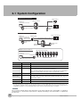
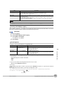
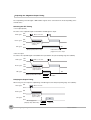
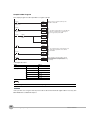
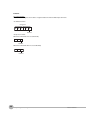
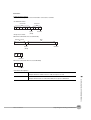
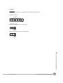
I/O Signal Circuit Diagrams
NPN
PNP
Brown Power supply (24 VDC)
Load
24 VDC
Light blue OUT2 (ERROR)
Orange OUT1 (BUSY)
Black OUT0 (OR)
Blue
Installation and Connections
Internal circuits
24 VDC
Blue GND (0V)
Pink TRIG
Gray IN0
Green IN1
IN2
Red
White IN3
Purple IN4
Yellow IN5
Power supply (24 VDC)
TRIG
IN0
IN1
IN2
IN3
IN4
IN5
2
Internal circuits
Black OUT0 (OR)
Orange OUT1 (BUSY)
Light blue OUT2 (ERROR)
Brown
Pink
Gray
Green
Red
White
Purple
Yellow
Load
GND (0V)
Important
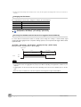
Preventing Chattering
• The Sensor is equipped with an anti-chattering function, but if the chattering is 100 µs or longer, a faulty input may
occur. (Input signals of 99 µs or shorter are ignored. Signals of 100 µs or longer are treated as input signals.)
• Use no-contact output devices (e.g., SSR or PLC transistor output) for the input signals. If contacts (e.g., relay) are
used, chattering may cause the trigger to be input again during execution of a measurement.
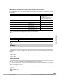
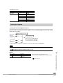
Power Supply Specifications When a Switching Regulator Is Connected
Use a power supply that meets the following specifications. (The power supply is sold separately.)
Item
Description
Power supply voltage
24 VDC (21.6 to 26.4 V)
Output current
3.75 A min.
Recommended Power Supply
S8VS-09024@ (24 VDC, 3.75 A)
External power supply terminal screws
M4 (tightening torque: 1.2 N·m)
Important
Supply power from a DC power supply for which measures have been applied to prevent high voltages (e.g., a safety
extra low voltage circuit).
If UL certification is required for the overall system, use a UL Class II DC power supply.
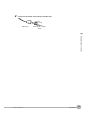
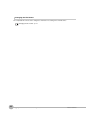
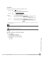
Attaching the LED Warning Label
Attach the enclosed LED warning label to the cable or other location. The LED warning label must be attached
to a location that is readily visible from the Sensor.
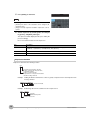
Attachment Example
Warning Label
Warning Label
10-5 LED Safety p. 200
FQ User’s Manual
Wiring
29