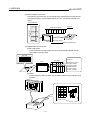
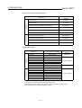
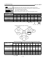
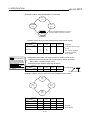
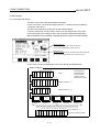
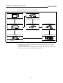
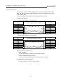
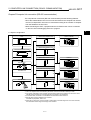
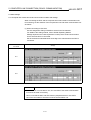
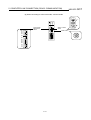
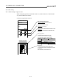
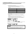
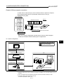
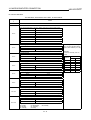
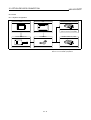
1
, GOT-A900 Series User s Manual (SW4D5C-GOTR-PACKE compatible Connection System Manual) MITSUBISHI Graphic Operation Terminal • SAFETY PRECAUTIONS • (Always read these instructions before using this equipment.) Before using this product, please read this manual and the relevant manuals introduced in this manual carefully and pay full attention to safety to handle the product correctly. The instructions given in this manual are concerned with this product. For the safety instructions of the programmable controller system, please read the CPU module user's manual. In this manual, the safety instructions are ranked as "DANGER" and "CAUTION". DANGER Indicates that incorrect handling may cause hazardous conditions, resulting in death or severe injury. ! CAUTION Indicates that incorrect handling may cause hazardous conditions, resulting in medium or slight personal injury or physical damage. ! Note that the ! CAUTION level may lead to a serious consequence according to the circumstances. Always follow the instructions of both levels because they are important to personal safety. Please save this manual to make it accessible when required and always forward it to the end user. [Design Instructions] ! DANGER • Some failures of the GOT main unit, communication module, communication board or cable may keep the outputs on or off. An external monitoring circuit should be provided to check for output signals which may lead to a serious accident. Not doing so can cause an accident due to false output or malfunction. • If a communication fault (including cable disconnection) occurs during monitoring on the GOT, communication between the GOT and PLC CPU is suspended and the GOT becomes inoperative. For bus connection : The CPU becomes faulty and the GOT inoperative. For other than bus connection : The GOT becomes inoperative. A system where the GOT is used should be configured to perform any significant operation to the system by using the switches of a device other than the GOT on the assumption that a GOT communication fault will occur. Not doing so can cause an accident due to false output or malfunction. ! CAUTION • Do not bundle the control and communication cables with main-circuit, power or other wiring. Run the above cables separately from such wiring and keep them a minimum of 100mm apart. Not doing so noise can cause a malfunction. A-1 [Mounting Instructions] ! DANGER • Before installing or removing the GOT main unit to or from an enclosure, always switch off the GOT power externally in all phases. Not doing so can cause a module failure or malfunction. • Before installing or removing the communication board, communication module, memory board, external I/O interface unit, or memory card interface unit, be sure to switch off the GOT power externally in all phases. Not doing so can cause a module failure or malfunction. ! CAUTION • The GOT should be used in the environment given in the general specifications of the GOT user's manual. Not doing so can cause an electric shock, fire, malfunction or product damage or deterioration. • When mounting the GOT main unit to an enclosure, tighten the mounting screws in the specified torque range. Undertightening can cause a drop, short circuit or malfunction. Overtightening can cause a drop, short circuit or malfunction due to the damage of the screws or module. • When loading the communication board or communication module to the GOT main unit, fit it to the connection interface of the GOT and tighten the mounting screws in the specified torque range. Undertightening can cause a drop, failure or malfunction. Overtightening can cause a drop, failure or malfunction due to the damage of the screws or module. • When loading the memory board into the GOT main unit, load it into its corresponding GOT slot and tighten the mounting screws in the specified torque range. Undertightening can cause a malfunction due to a contact fault. Overtightening can cause a malfunction due to the damage of the screws or module. • When loading the PC card into the GOT main unit, insert and push it into its corresponding GOT slot until the PC card eject button comes up. Not doing so can cause a malfunction due to a contact fault. • Before loading or unloading the PC card to or from the GOT, set the memory card access switch to the OFF position. Not doing so can cause the PC card data to be corrupted. A-2 [Wiring Instructions] ! DANGER • Before starting wiring, always switch off the GOT power externally in all phases. Not doing so may cause an electric shock, product damage or malfunction. ! CAUTION • Always earth the FG, LG and earth terminals of the GOT power supply section to the protective earth conductor. Not doing so may cause an electric shock or malfunction. • Correctly wire the power supply module on the GOT after confirming the rated voltage and terminal arrangement of the product. Not doing so can cause a fire or failure. • Tighten the terminal screws of the GOT power supply section in the specified torque range. Undertightening can cause a short circuit or malfunction. Overtightening can cause a short circuit or malfunction due to the damage of the screws or module. • Exercise care to avoid foreign matter such as chips and wire offcuts entering the module. Not doing so can cause a fire, failure or malfunction. • Plug the bus connection cable by inserting it into the connector of the connected module until it "clicks". After plugging, check that it has been inserted snugly. Not doing so can cause a malfunction due to a contact fault. • Plug the communication cable into the connector of the connected module and tighten the mounting and terminal screws in the specified torque range. Undertightening can cause a short circuit or malfunction. Overtightening can cause a short circuit or malfunction due to the damage of the screws or module. [Test Operation Instructions] ! DANGER • Before performing test operation (bit device on/off, word device's present value changing, timer/counter's set value and present value changing, buffer memory's present value changing) for a user-created monitor screen, system monitoring, special module monitoring or ladder monitoring, read the manual carefully to fully understand how to operate the equipment. During test operation, never change the data of the devices which are used to perform significant operation for the system. False output or malfunction can cause an accident. A-3 [Startup/Maintenance Instructions] ! DANGER • When power is on, do not touch the terminals. Doing so can cause an electric shock or malfunction. • Do not change the extension stage setting switch or the I/O slot setting switch. Doing so can cause malfunction. • Before starting cleaning or terminal screw retightening, always switch off the power externally in all phases. Not switching the power off in all phases can cause a module failure or malfunction. Undertightening can cause a short circuit or malfunction. Overtightening can cause a short circuit or malfunction due to the damage of the screws or module. ! CAUTION • Do not disassemble or modify the module. Doing so can cause a failure, malfunction, injury or fire. • Do not touch the conductive and electronic parts of the module directly. Doing so can cause a module malfunction or failure. • The cables connected to the module must be run in ducts or clamped. Not doing so can cause the module or cable to be damaged due to the dangling, motion or accidental pulling of the cables or can cause a malfunction due to a cable connection fault. • When unplugging the cable connected to the module, do not hold and pull the cable portion. Doing so can cause the module or cable to be damaged or can cause a malfunction due to a cable connection fault. [Disposal Instructions] ! CAUTION • When disposing of the product, handle it as industrial waste. A-4 Revisions *The manual number is given on the bottom left of the back cover. Print Date Jan.,2000 May.,2000 *Manual Number SH(NA)-080070-A SH(NA)-080070-B Revision First edition Partial additions Section 3.1, 4.1.3, 14.4, 15.1.1, 15.1.2, 15.1.3, 15.1.4, 15.1.6 This manual confers no industrial property rights or any rights of any other kind, nor does it confer any patent licenses. Mitsubishi Electric Corporation cannot be held responsible for any problems involving industrial property rights which may occur as a result of using the contents noted in this manual. 2000 MITSUBISHI ELECTRIC CORPORATION A-5 INTRODUCTION Thank you for choosing the Mitsubishi Graphic Operation Terminal. Before using the equipment, please read this manual carefully to use the equipment to its optimum. Please forward a copy of this manual to the end user. Whereabouts and Usage of This Manual The manuals relating to SW4D5C-GOTR-PACKE are available in the following types. The manuals are classified according to their purposes. Please read the proper manuals to understand the handling, operation and functions of the GOT unit and SW4D5C-GOTR-PACKE. [ A985GOT Graphic Operation Terminal User’s Manual(Hardware) ] • To know the features of A985GOT unit. • To confirm the specifications of A985GOT unit. • To know the part names of A985GOT unit. • To know how to install and wire A985GOT unit. • To know the outline dimension drawing of A985GOT unit. A985GOT Graphic Operation Terminal User's Manual (Hardware) Found in the packing of the A985GOT unit. [ A975GOT-TBA/TBD(-B), A970GOT-TBA/TBD(-B), A970GOT-SBA/SBD, A970GOT-LBA/LBD, A960GOTEBA/EBD User’s Manual(Hardware) ] • To know the features of A975GOT/A970GOT/A960GOT unit. A975GOT-TBA/TBD(-B) A970GOT-TBA/TBD(-B) • To confirm the specifications of A975GOT/A970GOT/A960GOT unit. A970GOT-SBA/SBD A970GOT-LBA/LBD • To know the part names of A975GOT/A970GOT/A960GOT unit. A960GOT-EBA/EBD user's Manual • To know how to install and wire A975GOT/A970GOT/A960GOT (Hardware) unit. • To know the outline dimension drawing of A975GOT/A970GOT/A960GOT unit. Found in the packing of the A975GOT/ A970GOT/A960GOT unit. [ A985GOT-TBA-EU, A975GOT-TBA-EU, A970GOT-TBA-EU, A970GOT-SBA-EU, A960GOT-EBA-EU User’s Manual(Hardware) ] • To know the features of the GOT-A900 series EMC directive Low voltage directive compliant unit. • To confirm the specifications of the GOT-A900 series EMC directive Low voltage directive compliant unit. • To know the part names of the GOT-A900 series EMC directive Low voltage directive compliant unit. • To know how to install and wire the GOT-A900 series EMC directive Low voltage directive compliant unit. • To know the outline dimension drawing of the GOT-A900 series EMC directive Low voltage directive compliant unit. A-6 A985GOT-TBA-EU A975GOT-TBA-EU A970GOT-TBA-EU A970GOT-SBA-EU A960GOT-EBA-EU User's Manual (Hardware) Found in the packing of the A985GOT-TBA-EU, A975GOT-TBA-EU, A970GOT-TBA-EU, A970GOT-SBA-EU, A960GOT-EBA-EU unit. [ A950GOT-TBD/SBD/LBD (-M3), A951GOT-QTBD/QSBD/QLBD (-M3), A951GOT-TBD/SBD/LBD (-M3), A953GOT-TBD/SBD/LBD (-M3), A956GOT-TBD/SBD/LBD (-M3) User's Manual(Hardware) ] • To know the features of A950GOT/A951GOT/A953GOT/A956GOT unit. • To confirm the specifications of A950GOT/A951GOT/A953GOT/A956GOT unit. • To know the part names of A950GOT/A951GOT/A953GOT/A956GOT unit. • To know how to install and wire A950GOT/A951GOT/A953GOT/A956GOT unit. • To know the outline dimension drawing of A950GOT/A951GOT/A953GOT/A956GOT unit. A950GOT-TBD/SBD/LBD(-M3) A951GOT-QTBD/QSBD/QLBD(-M3) A951GOT-TBD/SBD/LBD(-M3) A953GOT-TBD/SBD/LBD(-M3) A956GOT-TBD/SBD/LBD(-M3) User's Manual (Hardware) Found in the packing of the A950GOT/ A951GOT/A953GOT/ A956GOT unit. [ GOT-A900 Series Option Unit User's Manuals ] • To know the features of the corresponding GOT-A900 series option unit. • To confirm the specifications of the corresponding GOT-A900 series option unit. • To know the part names of the corresponding GOT-A900 series option unit. • To know the outline dimension drawing of the corresponding GOT-A900 series option unit. GOT-A900 Series Option Unit User's Manuals Found in the packing of the corresponding GOT-A900 series option unit. [ A985GOT/ A975GOT/ A970GOT/ A960GOT User’s Manual ] • To know the features of A985GOT/ A975GOT/ A970GOT/ A960GOT unit. • To confirm the component devices of A985GOT/ A975GOT/ A970GOT/ A960GOT unit. • To confirm the specifications of A985GOT/ A975GOT/ A970GOT/ A960GOT unit. • To know the part names of A985GOT/ A975GOT/ A970GOT/ A960GOT unit. • To fit various units to A985GOT/ A975GOT/ A970GOT/ A960GOT unit. • To know how to install and wire A985GOT/ A975GOT/ A970GOT/ A960GOT unit. • To know how to maintain and inspect A985GOT/ A975GOT/ A970GOT/ A960GOT unit. • To confirm the error codes of A985GOT/ A975GOT/ A970GOT/ A960GOT unit. • To know the outline dimension drawing of A985GOT/ A975GOT/ A970GOT/ A960GOT unit. A-7 A985GOT/A975GOT /A970GOT/A960GOT User's Manual Available as an option. [ A950GOT/ A951GOT/ A953GOT/ A956GOT User’s Manual ] • To know the features of A950GOT/ A951GOT/ 953GOT/ A956GOT unit. • To confirm the component devices of A950GOT/ A951GOT/ 953GOT/ A956GOT unit. • To confirm the specifications of A950GOT/ A951GOT/ 953GOT/ A956GOT unit. • To know the part names of A950GOT/ A951GOT/ 953GOT/ A956GOT unit. • To fit various units to A950GOT/ A951GOT/ 953GOT/ A956GOT unit. • To know how to install and wire A950GOT/ A951GOT/ 953GOT/ A956GOT unit. • To know how to maintain and inspect A950GOT/ A951GOT/ 953GOT/ A956GOT unit. • To confirm the error codes of A950GOT/ A951GOT/ 953GOT/ A956GOT unit. • To know the outline dimension drawing of A950GOT/ A951GOT/ 953GOT/ A956GOT unit. A950GOT/A951GOT /A953GOT/A956GOT User's Manual Available as an option. [ GOT-A900 Series User’s Manual(SW4D5C-GOTR-PACKE compatible Connection System Manual) ] • To know the connection forms available for the GOT-A900 series. • To confirm the specifications of each connection form. • To know the system configuration of each connection form. • To know how to set the unit used. • To confirm the connection diagrams of the connection cables. SW4D5C-GOTR-PACKE Contained in the SW4D5C-GOTR-PACKE as PDF data. * The printed matter is also available as an option. [ SW4D5C-GOTR-PACKE(V) Operating Manual ] • To install the software into the personal computer. • To start each software. • To know how to connect the personal computer and GOT. • To know the screen makeup of the software. • To grasp the outline of various monitoring functions. • To know the procedure of displaying the monitor screen. • To know how to use the help function. SW4D5C-GOTR-PACKE(v) Operating Manual Found in the packing of SW4D5C-GOTR-PACKE. * Contained also in the SW4D5C-GOTRPACKE as PDF data. [ SW4D5C-GOTR-PACKE Help Functions] • To confirm how to operate each software of SW4D5C-GOTRPACKE. • To confirm how to set various object functions. SW4D5C-GOTR-PACKE Incorporated in each software of SW4D5C-GOTR-PACKE [ GOT-A900 Series Operating Manual (SW4D5C-GOTR-PACKE compatible Extended • Option Functions Manual ) ] • To perform the utility function. • To perform the system monitoring function. • To perform the ladder monitoring function. • To perform the special function unit monitoring function. • To perform the network monitoring function. • To perform the list editor function. SW4D5C-GOTR-PACKE Contained in the SW4D5C-GOTR-PACKE as PDF data. * The printed matter is also available as an option. [ GOT Operations Guide ] • To learn the sequence of operations by creating a simple screen using the drawing software (the screen displays of the drawing software introduced in the GOT Operations Guide are partly different from those of SW4D5C-GOTR-PACKE). A-8 GOT Operations Guide Contained in the GOT Operations Guide. Abbreviations, generic terms and special terms used in this manual Abbreviations, generic terms and special terms used in this manual are described as follows: Abbreviations, generic terms and special terms A985GOT A975GOT A970GOT A97*GOT A960GOT A956GOT A953GOT A951GOT A951GOT-Q A950GOT A950 handy GOT A95*GOT GOT Memory OS A9GT-QBUSS A9GT-QBUS2S A9GT-BUSS A9GT-BUS2S Bus connection board A9GT-RS4 A9GT-RS2 A9GT-RS2T Serial communication board Communication board A9GT-QBUS2SU A9GT-BUSSU A9GT-BUS2SU A7GT-BUSS A7GT-BUS2S Bus connection unit A7GT-J71AP23 A7GT-J71AR23 A7GT-J71AT23B Data link unit A7GT-J71LP23 A7GT-J71BR13 Network unit A8GT-J61BT13 A8GT-J61BT15 CC-Link communication unit Communication unit Protection sheet Backlight Debug stand PC card ( memory card ) Memory board Description Generic term of A985GOT-TBA, A985GOT-TBD and A985GOT-TBA-EU Generic term of A975GOT-TBA-B, A975GOT-TBD-B, A975GOT-TBA, A975GOT-TBD and A975GOT-TBA-EU Generic term of A970GOT-TBA-B A970GOT-TBD-B, A970GOT-TBA, A970GOT-TBD, A970GOTSBA, A970GOT-SBD, A970GOT-LBA, A970GOT-LBD, A970GOT-TBA-EU and A970GOT-SBA-EU Generic term of A975GOT and A970GOT Generic term of A960GOT-EBA, A960GOT-EBD and A960GOT-EBA-EU Generic term of A956GOT-TBD, A956GOT-SBD, A956GOT-LBD, A956GOT-TBD-M3, A956GOTSBD-M3 and A956GOT-LBD-M3 Generic term of A953GOT-TBD, A953GOT-SBD, A953GOT-LBD, A953GOT-TBD-M3, A953GOTSBD-M3 and A953GOT-LBD-M3 Generic term of A951GOT-TBD, A951GOT-SBD, A951GOT-LBD, A951GOT-TBD-M3, A951GOTSBD-M3 and A951GOT-LBD-M3 Generic term of A951GOT-QTBD, A951GOT-QSBD, A951GOT-QLBD, A951GOT-QTBD-M3, A951GOTQSBD-M3 and A951GOT-QLBD-M3 Generic term of A950GOT-TBD, A950GOT-SBD, A950GOT-LBD, A950GOT-TBD-M3, A950GOTSBD-M3 and A950GOT-LBD-M3 Generic term of A953GOT-SBD-M3-H and A953GOT-LBD-M3-H Generic term of A956GOT, A953GOT, A951GOT, A951GOT-Q, A950GOT and A950 handy GOT Generic term of A985GOT, A97*GOT, A960GOT and A95*GOT Abbreviation of memory (flash memory) in the GOT Abbreviation of GOT system software Abbreviation of A9GT-QBUSS type bus connection board Abbreviation of A9GT-QBUS2S type multi-drop bus connection board Abbreviation of A9GT-BUSS type bus connection board Abbreviation of A9GT-BUS2S type multi-drop bus connection board Generic term of A9GT-QBUSS, A9GT-QBUS2S, A9GT-BUSS and A9GT-BUS2S Abbreviation of A9GT-RS4 type serial communication board Abbreviation of A9GT-RS2 type serial communication board Abbreviation of A9GT-RS2T type serial communication board Generic term of A9GT-RS4, A9GT-RS2 and A9GT-RS2T Generic term of bus connection board and serial communication board Abbreviation of A9GT-QBUS2SU type multi-drop bus connection unit Abbreviation of A9GT-BUSSU type bus connection unit Abbreviation of A9GT-BUS2SU type multi-drop bus connection unit Abbreviation of A7GT-BUSS type bus connection unit Abbreviation of A7GT-BUS2S multi-drop bus connection unit Generic term of A9GT-QBUS2SU, A9GT-BUS2SU, A9GT-BUS2SU, A7GT-BUSS and A7GT-BUS2S Abbreviation of A7GT-J71AP23 type data link unit Abbreviation of A7GT-J71AR23 type data link unit Abbreviation of A7GT-J71AT23B type data link unit Generic term of A7GT-J71AP23, A7GT-J71AR23 and A7GT-J71AT23B Abbreviation of A7GT-J71LP23 type network unit Abbreviation of A7GT-J71BR13 type network unit Generic term of A7GT-J71LP23 and A7GT-J71BR13 Abbreviation of A8GT-J61B13 CC-Link communication unit Abbreviation of A8GT-J61B15 CC-Link communication unit Generic term of A8GT-J61BT13 and A8GT-J61BT15 Generic term of bus connection unit, data link unit, network unit and CC-Link communication unit Abbreviation of A9GT-80PSC, A9GT-70PSC, A9GT-60PSC and A9GT-50PSC type transparent protection sheets Abbreviation of A9GT-80LTT, A9GT-70LTTB, A9GT-70LTT, A9GT-70LTS and A9GT-50LT type backlights Abbreviation of A9GT-80STAND, A9GT-70STAND and A9GT-50STAND type debug stand Abbreviation of PC card with PCMCIA Ver.2.1 Abbreviation of A9GT-FNB, A9GT-FNB1M, A9GT-FNB2M, A9GT-FNB4M, A9GT-FNB8M, A9GTQFNB, A9GT-QFNB4M, A9GT-QFNB8M type option function memory board A-9 Abbreviations, generic terms and special terms External I/O unit Printer interface unit Memory card interface unit Attachment QCPU (Q Mode) QCPU (A Mode) QCPU QnACPU (Large Type) QnACPU (Small Type) QnACPU AnUCPU AnACPU AnNCPU ACPU (Large Type) A2US(H)CPU AnS(H)CPU A1SJ(H)CPU ACPU (Small Type) ACPU FX0 series FX0N series FX0S series FX1 series FX1S series FX2 series FX2C series FX2N series FX2NC series Description Drawing software Data conversion software Debug software Object Windows95 Abbreviation of A9GT-70KBF and A8GT-50KBF type external I/O interface unit Abbreviation of A9GT-50PRF type printer interface unit Abbreviation of A1SD59J-MIF memory card interface unit Generic term of A77GT-96ATT/A85GT-95ATT/A87GT-96ATT/A87GT-97ATT attachments Generic term of Q02CPU, Q02HCPU, Q06HCPU, Q12HCPU and Q25HCPU CPU units Generic term of Q02CPU-A, Q02HCPU-A and Q06HCPU-A CPU units Generic term of QCPU (Q Mode) and QCPU (A Mode) Generic term of Q2ACPU, Q2ACPU-S1, Q3ACPU, Q4ACPU and Q4ARCPU CPU units Generic term of Q2ASCPU, Q2ASCPU-S1, Q2ASHCPU and Q2ASHCPU-S1 CPU units Generic term of QnACPU (Large Type) and QnACPU (Small Type) Generic term of A2UCPU, A2UCPU-S1, A3UCPU and A4UCPU CPU units Generic term of A2ACPU, A2ACPU-S1 and A3ACPU CPU units Generic term of A1NCPU, A2NCPU, A2NCPU-S1 and A3NCPU CPU units Generic term of AnUCPU, AnACPU and AnNCPU CPU units Generic term of A2USCPU, A2USCPU-S1 and A2USHCPU-S1 CPU units Generic term of A1SCPU, A1SHCPU, A2SCPU and A2SHCPU CPU units Generic term of A1SJCPU-S3 and A1SJHCPU CPU units Generic term of A2US(H)CPU, AnS(H)CPU and A1SJ(H)CPU CPU units Generic term of ACPU (Large Type), ACPU (Small Type) and A1FXCPU CPU units Generic term of FX0 series CPU unit Generic term of FX0N series CPU unit Generic term of FX0S series CPU unit Generic term of FX1 series CPU unit Generic term of FX1S series CPU unit Generic term of FX2 series CPU unit Generic term of FX2C series CPU unit Generic term of FX2N series CPU unit Generic term of FX2NC series CPU unit Generic term of FX0 series, FX0N series, FX0S series, FX1 series, FX1S series, FX2 series , FX2C series, FX2N series, FX2NC series CPU unit Generic term of A373UCPU, A373UCPU-S3, A273UCPU, A273UHCPU, A273UHCPU-S3, A171SCPU-S3, A171SHCPU, A172SHCPU CPU unit Generic term of LM610, LM7600, LM8000 CPU unit Generic term of C200HS, C200H, C200HX, C200HG, C200HE, CQM1, C1000H,C2000H,CV1000 CPU unit Generic term of GL60S, GL60H, GL70H, GL120, GL130, CP-9200SH, CP-9300MS, MP-920, MP-930, CP-9200(H) and PROGIC-8 CPU unit Generic term of SLC 5/03, SLC 5/04 CPU unit Generic term of JW-21CU, JW-22CU, JW-31CUH, JW-32CUH, JW-33CUH, JW-50CUH, JW-70CUH, JW-100CUH CPU unit Generic term of T3, T3H CPU unit Generic term of SIMATIC S7-300 Series and SIMATIC S7-400 Series CPU unit Generic term of Omron PLC, Yasukawa PLC , Allen-Bradley PLC , Sharp PLC , Toshiba PLC and SIEMENS PLC CPU unit Generic term of SW4D5C-GOTR-PACKE software package and SW4D5C-GOTR-PACKEV software package Abbreviation of image creation software GOT Screen Designer for GOT900 Abbreviation of data conversion software GOT Converter for GOT900 Abbreviation of debugging software GOT Debugger Setting data for dynamic image 1 Abbreviation of Microsoft Windows95∗ Windows98 Abbreviation of Microsoft Windows98∗ Windows NT4.0 Windows Acrobat Reader Personal Computer Abbreviation of Microsoft Windows NT Workstation 4.0∗ Generic term of Windows95, Windows98 and Windows NT4.0 2 Abbreviation of Adobe Acrobat Reader3.0 ∗ Windows compatible Personal Computer that can install SW4D5C-GOTR-PACKE FXCPU Motion controller CPU FA controller Omron PLC Yasukawa PLC Allen-Bradley PLC Sharp PLC Toshiba PLC SIEMENS PLC Other PLC SW4D5C-GOTR-PACKE 1 1 *1 Microsoft Windows95, Microsoft Windows98 and Microsoft Windows NT Workstation 4.0 are the trademarks of Microsoft Corporation, U.S. *2 Adobe and Adobe Acrobat are the trademarks of Adobe Systems Incorporated. (C)1998 Adobe Systems Incorporated. All right reserved. A - 10 Manual The following manuals related to this product are available. Obtain the manuals as required the according to this table. • Related manual Manual name Manual number (Model code) A985GOT/A975GOT/A970GOT/A960GOT User’s Manual Explains the specifications, general system configuration, component devices, part names, option unit loading methods, installation and wiring methods, maintenance and inspection methods, and error codes of A985GOT/A975GOT/A970GOT/A960GOT unit. (Available as option) A950GOT/A951GOT/A953GOT/A956GOT User’s Manual Explains the specifications, general system configuration, component devices, part names, option unit loading methods, installation and wiring methods, maintenance and inspection methods, and error codes of A950GOT/A951GOT/A953GOT/A956GOT unit. (Available as option) GOT-A900 Series User’s Manual (SW4D5C-GOTR-PACKE compatible Connection System Manual) Gives the specifications, system configuration, setting method and connection diagram of each connection form available for the GOT-A900 series. (Available as option) GOT-A900 Series Operating Manual (SW4D5C-GOTR-PACKE compatible Extended • Option Functions Manual) Provides the specifications of the utility, system monitoring, ladder monitoring, special function unit monitoring, network monitoring functions and list editor functions available for the GOT-A900 series and how to operate the dedicated monitor screen. (Available as option) SW4D5C-GOTR-PACKE(V) Operating Manual Deals with how to install and start the SW4D5C-GOTR-PACKE, its system configuration, the screen makeup of the software package, the general description of various monitoring functions, the procedure for displaying the monitor screen on the GOT, and how to use the help function. (Found in the packing of the SW4D5C-GOTR-PACKE) A9GT-QBUSS Type Bus Connection Board User's Manual Describes specifications, part names and installation of A9GT-QBUSS. (with A9GT-QBUSS) A9GT-QBUS2S Type Multi-Drop Bus Connection Board User's Manual Describes specifications, part names and installation of A9GT-QBUS2S. (with A9GT-QBUS2S) A9GT-QBUS2SU Type Multi-Drop Bus connection unit User's Manual Describes specifications, part names and installation of A9GT- QBUS2SU. (with A9GT- QBUS2SU) A9GT-BUSSU Type Bus connection unit User's Manual Describes specifications, part names and installation of A9GT-BUSSU. (with A9GT-BUSSU) A9GT-BUS2SU Type Multi-Drop Bus connection unit User's Manual Describes specifications, part names and installation of A9GT-BUS2SU. (with A9GT-BUS2SU) A9GT-BUSS Type Bus Connection Board User's Manual Describes specifications, part names and installation of A9GT-BUSS. (with A9GT-BUSS) A9GT-BUS2S Type Multi-Drop Bus Connection Board User's Manual Describes specifications, part names and installation of A9GT-BUS2S. (with A9GT-BUS2S) A7GT-BUSS Type bus connection unit User's Manual Describes specifications, part names and operation of A7GT-BUSS. (with A7GT-BUSS) A - 11 SH-4005 (13JL70) SH-080018 (13JL92) SH-080070 (13JR11) SH-080069 (13J979) IB-0800094 (13J978) IB-0800073 (13JQ75) IB-0800074 (13JQ76) IB-0800083 (13JQ83) IB-0800076 (13JQ78) IB-0800077 (13JQ79) IB-68953 (13JM87) IB-68954 (13JM88) IB-66760 (13JL07) Manual name Manual number (Model code) A7GT-BUS2S Type multi-drop bus connection unit User's Manual Describes specifications, part names and operation of A7GT-BUS2S. (with A7GT-BUS2S) A9GT-RS4 Type Serial Communication Board User's Manual Describes specifications, part names and installation of A9GT-RS4. (with A9GT-RS4) A9GT-RS2 Type Serial Communication Board User's Manual Describes specifications, part names and installation of A9GT-RS2. (with A9GT-RS2) A9GT-RS2T Type Serial Communication Board User's Manual Describes specifications, part names and installation of A9GT-RS2T. (with A9GT-RS2T) A7GT-J71AP23/R23 Type Data Link Unit User's Manual Describes specifications, part names and installation of A7GT-J71AP23/R23. (with A7GT-J71AP23/R23) A7GT-J71AT23B Type Data Link Unit User's Manual Describes specifications, part names and installation of A7GT-J71AT23B. (with A7GT-J71AT23B) A7GT-J71LP23/BR13 Type Network Unit User's Manual Describes specifications, part names and installation of A7GT-J71LP23/BR13. (with A7GT-J71LP23/BR13) A8GT-J61BT13 Type CC-Link Communication Unit User's Manual Describes specifications, part names and installation of A8GT-J61BT13. (with A8GT-J61BT13) A8GT-J61BT15 Type CC-Link Communication Unit User's Manual Describes specifications, part names and installation of A8GT-J61BT15. (with A8GT-J61BT15) A9GT-80LTT Type Back light Unit User's Manual Describes specifications, part names and installation of A9GT-80LTT. (with A9GT-80LTT) A9GT-70LTT Type Back light Unit User's Manual Describes specifications, part names and installation of A9GT-70LTT. (with A9GT-70LTT) A9GT-70LTS Type Back light Unit User's Manual Describes specifications, part names and installation of A9GT-70LTS. (with A9GT-70LTS) A9GT-70LTTB Type Back light Unit User's Manual Describes specifications, part names and installation of A9GT-70LTTB. (with A9GT-70LTTB) A9GT-50LT type backlight User's Manual Describes specifications and operation of A9GT-50LT. (with A9GT-50LT) A9GT-80STAND User's Manual Describes specifications, part names and installation of A9GT-80STAND. (with A9GT-80STAND) A9GT-70STAND User's Manual Describes specifications, part names and installation of A9GT-70STAND. (with A9GT-70STAND) A9GT-50STAND User's Manual Describes specifications and operation of A9GT-50STAND. (with A9GT-50STAND) A - 12 IB-66761 (13JL08) IB-68955 (13JM89) IB-68956 (13JM90) IB-0800022 (13JQ38) IB-66438 (13JE26) IB-66439 (13JA81) IB-66558 (13JE94) IB-66838 (13JL56) IB-66788 (13JL29) IB-80027 (13JQ21) IB-68982 (13JM97) IB-68984 (13JM99) IB-80033 (13JQ25) IB-0800020 (13JQ29) IB-80028 (13JQ22) IB-68981 (13JM96) IB-0800021 (13JQ30) Manual name Manual number (Model code) Add-on memory board for A9GT-FNB, A9GT-FNB1M, A9GT-FNB2M, A9GT-FNB4M and A9GTFNB8M type option function Describes specifications, part names and installation of A9GT-FNB (1M/2M/4M/8M). (with A9GT-FNB (1M/2M/4M/8M)) IB-68975 (13JM91) Add-on memory board for A9GT-QFNB, A9GT-QFNB4M and A9GT-QFNB8M type option function Describes specifications, part names and installation of A9GT-QFNB (4M/8M). (with A9GT- QFNB (4M/8M)) IB-0800051 (13JQ62) A9GT-70KBF Type External I/O Interface Unit User's Manual Describes specifications, system configurations, part names and installation/wiring methods of A9GT-70KBF. (with A9GT-70KBF) IB-80018 (13JQ14) A8GT-50KBF Type External I/O Interface Unit User's Manual Describes specifications, system configurations, part names and installation/wiring methods of A8GT-50KBF. (with A8GT-50KBF) IB-66787 (13JL28) A9GT-50PRF type printer interface unit user's manual Describes specifications, system configuration, part names, installation method and external dimensions of A9GT-50PRF. (with A9GT-50PRF) IB-0800019 (13JQ28) A8GT-TK Type Numerical Keypad Panel User's Manual Describes specifications, part names and installation of A8GT-TK. (with A8GT-TK) A9GT-QCNB Type bus connector conversion box User's Manual Describes specifications, part names and installation of A9GT-QCNB. (with A9GT-QCNB) A7GT-CNB Type bus connector conversion box User's Manual Describes specifications, part names and installation of A7GT-CNB. IB-0800082 (13JQ82) BCN-P5138 (with A7GT-CNB) A - 13 IB-66832 (13JL51) CONTENTS 1 Overview.............................................................................................................. 1 - 1 to 1 - 6 1.1 Connection supported with GOT ........................................................................................................... 1 - 1 2 Specification ...................................................................................................... 2 - 1 to 2 - 24 2.1 PLC CPU that allows monitoring ........................................................................................................... 2 - 1 2.2 Device name that allows monitoring...................................................................................................... 2 - 2 2.3 Monitoring of special function unit ........................................................................................................ 2 -11 2.4 Access range for monitoring ................................................................................................................. 2 -12 2.4.1 Data link system access range for monitoring ........................................................................... 2 -12 2.4.2 Network system access range for monitoring ............................................................................ 2 -14 2.4.3 CC-Link system access range for monitoring ............................................................................ 2 -22 2.4.4 Access range for monitoring when using MELSEC-FXCPU, other PLC and microcomputer connections................................................................................................. 2 -23 3 Bus connection .................................................................................................. 3 - 1 to 3 - 16 3.1 First step in bus connection ................................................................................................................... 3 - 1 3.1.1 GOT handling from PLC CPU in bus connection........................................................................ 3 - 1 3.1.2 Restriction on the number of GOTs by the PLC CPU connected to .......................................... 3 - 1 3.1.3 Power supply of PLC CPU and GOT .......................................................................................... 3 - 2 3.1.4 Restriction when PLC CPU is used in direct method.................................................................. 3 - 3 3.1.5 Precautions for use of A1SJCPU and A1SJHCPU..................................................................... 3 - 3 3.1.6 Precautions for GOT connection in duplex system..................................................................... 3 - 3 3.2 System configuration.............................................................................................................................. 3 - 4 3.2.1 Connection with QCPU (Q mode)................................................................................................ 3 - 4 3.2.2 Connection with QnACPU (large type) or ACPU (large type)..................................................... 3 - 5 3.2.3 Connection with QnACPU (small type) or ACPU (small type).................................................... 3 - 6 3.2.4 Connection with A0J2HCPU........................................................................................................ 3 - 7 3.2.5 Connection with motion controller CPU....................................................................................... 3 - 8 3.3 Initial settings ......................................................................................................................................... 3 -11 3.3.1 Connection with QCPU ............................................................................................................... 3 -11 3.3.2 Connection with other than QCPU.............................................................................................. 3 -13 4 Direct connection to CPU .................................................................................... 4 - 1 to 4 - 6 4.1 System configuration.............................................................................................................................. 4 - 1 4.1.1 When connecting to QCPU.......................................................................................................... 4 - 1 4.1.2 When connecting to QnACPU or ACPU...................................................................................... 4 - 1 4.1.3 When connecting to FXCPU........................................................................................................ 4 - 2 4.2 Connection cable.................................................................................................................................... 4 - 5 A - 14 5 Computer link connection (RS-422 communication)........................................... 5 - 1 to 5 - 8 5.1 System configuration.............................................................................................................................. 5 - 1 5.2 Initial settings .......................................................................................................................................... 5 - 2 5.2.1 Computer link module and serial communication module side settings.................................. 5 - 2 5.2.2 GOT side settings ...................................................................................................................... 5 - 6 5.3 Transmission specification..................................................................................................................... 5 - 6 5.4 Connection cable.................................................................................................................................... 5 - 7 6 Computer link connection (RS-232C communication) ........................................ 6 - 1 to 6 - 8 6.1 System configuration.............................................................................................................................. 6 - 1 6.2 Initial settings .......................................................................................................................................... 6 - 2 6.2.1 Computer link module and serial communication module side settings.................................. 6 - 2 6.2.2 GOT side settings ...................................................................................................................... 6 - 6 6.3 Transmission specification..................................................................................................................... 6 - 6 6.4 Connection cable.................................................................................................................................... 6 - 7 7 MELSECNET connection (data link system)....................................................... 7 - 1 to 7 - 2 7.1 System configuration.............................................................................................................................. 7 - 1 7.2 Switch setting of data link unit................................................................................................................ 7 - 2 7.3 Self-diagnosis test .................................................................................................................................. 7 - 2 8 MELSECNET connection (network system) ....................................................... 8 - 1 to 8 - 2 8.1 System configuration.............................................................................................................................. 8 - 1 8.2 Switch setting of network unit ................................................................................................................ 8 - 2 8.3 Self-diagnosis test .................................................................................................................................. 8 - 2 9 CC-Link connection ............................................................................................. 9 - 1 to 9 - 2 10 Omron PLC connection ............................................................................... 10 - 1 to 10 - 14 10.1 System configuration.......................................................................................................................... 10 - 1 10.1.1 System configuration of connection to C200H, C200HS and C200Hα series .................... 10 - 1 10.1.2 System configuration of connection to CQM1 ...................................................................... 10 - 2 10.1.3 System configuration of connection to C1000H and C2000H ............................................. 10 - 3 10.1.4 System configuration of connection to CV1000 ................................................................... 10 - 3 10.2 Initial setting........................................................................................................................................ 10 - 4 10.2.1 Switch setting of upper link unit............................................................................................. 10 - 4 10.2.2 Setting CV1000...................................................................................................................... 10 - 7 10.2.3 Initializing CQM1.................................................................................................................... 10 - 8 10.2.4 Communication board initialization program ........................................................................ 10 - 8 10.3 Connection cable................................................................................................................................ 10 - 9 10.3.1 RS-422 cable ......................................................................................................................... 10 - 9 10.3.2 RS-232C cable ....................................................................................................................10 - 11 10.3.3 Converter and connection cable used in CQM1 ................................................................10 - 13 11 Yasukawa PLC connection ........................................................................... 11 - 1 to 11 - 6 11.1 System configuration.......................................................................................................................... 11 - 1 11.2 Initial setting........................................................................................................................................ 11 - 2 11.3 Connection cable................................................................................................................................ 11 - 3 11.3.1 RS-422 cable ......................................................................................................................... 11 - 3 11.3.2 RS-232C cable ...................................................................................................................... 11 - 4 A - 15 12 Allen-Bradley PLC connection....................................................................... 12 - 1 to 12 - 2 12.1 System configuration.......................................................................................................................... 12 - 1 12.2 Communication settings of Allen-Bradley PLC ................................................................................. 12 - 1 12.3 Transmission specification................................................................................................................. 12 - 2 12.4 Connection cable................................................................................................................................ 12 - 2 13 Sharp PLC connection.................................................................................. 13 - 1 to 13 -10 13.1 System configuration.......................................................................................................................... 13 - 1 13.2 Initial setting........................................................................................................................................ 13 - 2 13.2.1 Connecting directly to the PLC CPU..................................................................................... 13 - 2 13.2.2 Connecting to the link unit ..................................................................................................... 13 - 4 13.3 Transmission specification................................................................................................................. 13 - 5 13.4 Connection cable................................................................................................................................ 13 - 6 13.4.1 RS-422 cable ......................................................................................................................... 13 - 6 13.4.2 RS-232C cable ...................................................................................................................... 13 - 8 14 Microcomputer connection .......................................................................... 14 - 1 to 14 - 14 14.1 System configuration.......................................................................................................................... 14 - 1 14.2 Connecting cable................................................................................................................................ 14 - 2 14.2.1 With connection to DTR ........................................................................................................ 14 - 2 14.2.2 Without connection to DTR ................................................................................................... 14 - 4 14.3 Transmission specification................................................................................................................. 14 - 5 14.4 Device data area ................................................................................................................................ 14 - 6 14.5 Communication commands ............................................................................................................... 14 - 7 14.5.1 Command list......................................................................................................................... 14 - 7 14.5.2 Data communication type...................................................................................................... 14 - 8 14.5.3 Precautions for use..............................................................................................................14 - 10 14.5.4 Batch read command(RD) ..................................................................................................14 - 11 14.5.5 Batch write command(WD) .................................................................................................14 - 12 14.5.6 Random read command(RR)..............................................................................................14 - 13 14.5.7 Random write command(RW).............................................................................................14 - 14 15 Option devices connection ........................................................................... 15 - 1 to 15 -18 15.1 Bar code reader.................................................................................................................................. 15 - 1 15.1.1 System configuration ............................................................................................................. 15 - 1 15.1.2 Communication setting of bar code reader........................................................................... 15 - 2 15.1.3 Connection cable................................................................................................................... 15 - 3 15.1.4 Recommended parts for customers and ordering method .................................................. 15 - 4 15.1.5 GOT setting method .............................................................................................................. 15 - 5 15.1.6 Bar code types that can be read with GOT .......................................................................... 15 - 5 15.2 Printer ................................................................................................................................................. 15 - 6 15.2.1 System configuration ............................................................................................................. 15 - 6 15.2.2 Connection cable................................................................................................................... 15 - 7 15.3 External I/O equipment ...................................................................................................................... 15 - 8 15.3.1 System configuration ............................................................................................................. 15 - 8 15.3.2 Connection cables ...............................................................................................................15 - 10 15.3.3 Wiring diagrams...................................................................................................................15 - 14 15.3.4 Recommended user-prepared articles and how to prepare them .....................................15 - 17 15.4 PC card.............................................................................................................................................15 - 18 15.4.1 System configuration ...........................................................................................................15 - 18 A - 16 16 Toshiba PLC connection ............................................................................... 16 - 1 to 16 - 2 16.1 System configuration.......................................................................................................................... 16 - 1 16.2 Initial settings...................................................................................................................................... 16 - 1 16.3 Connection cable................................................................................................................................ 16 - 2 17 SIEMENS PLC connection............................................................................ 17 - 1 to 17 - 4 17.1 System configuration.......................................................................................................................... 17 - 1 17.2 Initial settings...................................................................................................................................... 17 - 2 17.3 Connection cable................................................................................................................................ 17 - 3 Appendices .................................................................................................... App - 1 to App - 4 Appendix 1 System configuration example for microcomputer connection ...........................................App - 1 Appendix 1.1 System configuration................................................................................................App - 1 Appendix 1.2 GOT side communication setting and monitor screen setting details ....................App - 1 Appendix 1.3 Host side sample program .......................................................................................App - 3 Appendix 1.4 System operation overview......................................................................................App - 3 Index ............................................................................................................. Index-1 to Index-3 A - 17 MEMO A - 18 1. OVERVIEW MELSEC GOT Chapter1 Overview This manual describes the specifications, system configurations, setting method, connection cables and other information of each connection supported by the GOT. 1.1 Connection supported by GOT (1) Bus connection Bus connection is a way of using the extension connector of a base unit for connection of the GOT (connection by I/O bus) and this connection form has the fastest response to a PLC CPU among the GOT connection forms. Multiple GOTs can be connected in a position away from the PLC CPU to be connected to. However, only one GOT may be connected depending on the PLC CPU to be connected to. Connection with QCPU (Q Mode) Connection with QnACPU/ACPU (Large Type) Connection with QnACPU/ACPU (Small Type) Example: Connection with Q25HCPU Example: Connection with Q2ACPU Example: Connection with A2USCPU MAX 35m MAX 3 units MAX 36.6m MAX 37m MAX 3 units MAX 5 units *There are various precautions for bus connection according to the system selected. For details, refer to Chapter 3. (2) Direct connection to CPU You can connect the GOT with the PLC CPU by an RS-422/RS-232C cable and this is the most economical way of connection. 1-1 1 1. OVERVIEW MELSEC GOT (3) Computer link connection Since the GOT can be connected with a computer link unit on a 1:1 basis, several GOTs can be connected. (4) MELSECNET connection The GOT is used as a local station of the data link system or a normal station of the network system and allows remote control via network. Loop type Bus type (5) CC-Link connection The GOT is used as an intelligent device station or a remote device station of the CC-Link system and allows remote control via network. Partner manufacturer's product Remote I/O station Master station Intelligent device station/Remote device station Remote I/O station Local station 1-2 1. OVERVIEW MELSEC GOT (6) Omron PLC connection Allows monitoring by connecting to an Omron PLC. • CPUs that allow monitoring C200H, C200HS, C200H, CQM1, C1000H, C2000H, CV1000 RS-422 communication/RS232C communication enables monitoring. (7) Yasukawa PLC connection Allows monitoring by connecting to a Yasukawa PLC. • CPUs that allow monitoring GL60S, GL60H, GL70H, GL120, GL130, CP-9200SH, CP-9300MS, MP-920, MP-930, CP-9200(H), PROGIC-8 RS-422 communication/RS232C communication enables monitoring. (8) Allen-Bradley PLC connection Allows monitoring by connecting to the Allen-Bradley PLC. • CPUs that allow monitoring SLC 5/03, SLC 5/04 Monitored with RS-232C communication 1-3 1. OVERVIEW MELSEC GOT (9) Sharp PLC connection Allows monitoring by connecting to the Sharp PLC. • CPUs that allow monitoring JW-21CU, JW-22CU, JW-31CUH, JW-32CUH, JW-33CUH, JW-50CUH, JW-70CUH, JW-100CUH Monitored with RS-232C/RS-422 communication (10) Toshiba PLC connection Allows monitoring by connecting to a Toshiba PLC. • CPUs that allow monitoring T3, T3H Monitored with RS-422 communication (11) SIEMENS PLC connection Connecting to the HMI adaptor allows monitoring of multiple SIEMENS PLCs connected by PROFIBUS. • CPUs that allow monitoring SIMATIC S7-300 series, SIMATIC S7-400 series RS-232C communication PROFIBUS Monitoring allowed via HMI adaptor 1-4 1. OVERVIEW MELSEC GOT (12) Microcomputer connection Virtual device (D) of the GOT can be monitored by sending/receiving data from/to a personal computer, microcomputer board, PLC, etc. (hereinafter referred to as "host") Device data area D0 Memory D0 D2047 Write/read command E S T RW 0100000A01630362 T D3 X X D100 000A D163 0362 D2047 Interruption output Microcomputer board (13) Optional devices connection (a) Bar code reader If connected to a bar code reader, the GOT can write data read with the bar code reader to the PLC CPU. Bar code Device No. 123456789 PLC CPU GOT +0 Number of bytes 9 +1 Data 21 3231H +2 Data 43 3433H +3 Data 65 3635H +4 Data 87 3837H +5 Data 9 2039H (b) Printer If connected to a printer, the GOT can print data of alarm history and hard copy functions. 9 10 11 12 13 1-5 A-1 A-2 10 15 20 25 30 35 40 45 50 55 1. OVERVIEW MELSEC GOT (c) External I/O equipment By connection of input equipment (operation panel, ten-key panel, pushbuttons, etc.), you can write to devices, e.g. touch input, numerical input and screen switching, from outside the GOT. In addition, you can connect output equipment (lamps, relays, etc.) to provide outputs from the GOT to the outside. External input equipment Operation panel, pushbuttons, etc. Connector terminal block conversion unit External output equipment External I/O unit Lamp, relay, etc. (d) PC card Installation of PC card on the GOT allows storage of data used in the transfer data (system program, monitor screen data) and object function (alarm history function, recipe function, etc.). A985/ 97*/ 960GOT PC card Installation Installation A95*GOT A1SD59J-MIF A8GT-C05H 1-6 2. SPECIFICATION MELSEC GOT Chapter2 Specification 2.1 PLC CPU that allows monitoring The PLC CPU that can be monitored by the GOT changes with the system up to the PLC CPU monitored (connection form). The PLC CPUs that can be monitored by the GOT are indicated below per connection form. PLC CPU Monitored*1 Computer CPU Bus Link Direct Connection Connection Connection MELSECNET Connection Network system MELSEC NET/10H QCPU (Q mode) MELSEC NET/10 CC-Link Connection Data link system MELSEC NET/B,(II) Intelligent device station Remote device station*3 *4 QCPU (A mode) QnACPU ACPU Other than A1FXCPU *4 *5 *6 *6*7*8 *6 *6 *6 A1FXCPU FXCPU FA controller Motion controller CPU *8 Omron PLC Yasukawa PLC Allen-Bradley PLC Sharp PLC Toshiba PLC SIEMENS PLC *1 In a system where a remote I/O station exists, monitoring cannot be done independently of the PLC CPU and connection form. *2 Including the case where the MELSECNET/10H is used in the NET/10 mode. *3 For connection as a remote device station, only the link devices (RX, RY, RWw, RWr) assigned to the GOT may be monitored. *4 When creating a monitor screen (project data) with the drawing software, note the following two points. • When setting the monitor devices, note that the device ranges that can be monitored are the ranges for monitoring the ACPU (A3ACPU equivalent). • The PLC CPUs monitored are the QCPU (Q mode) and QnACPU, but the PLC type must be set to "MELSEC-A". *5 The A2CCPU and A2CCPUC24 do not allow bus connection. *6 When monitoring the AnNCPU(S1), A2SCPU, A0J2HCPU or A2CCPU, data cannot be written to the CPU earlier than the following version. AnNCPU(S1): Version L or later for the one with link, version H or later for the one without link A2SCPU: Version H or later A0J2HCPU: Version E or later A2CCPU: Version H or later *7 The A2CCPU does not allow computer link connection. *8 For computer link connection of the A2SCPU, A2SHCPU-S1, A2SHCPU, A1SHCPU, A1SJHCPU, A0J2HCPU, A171SHCPU and A172SHCPU, use the computer link module whose software version is version U or later. In addition, the A0J2-C214-S1 (A0J2HCPU-dedicated computer link module) cannot be used. 2-1 2 2. SPECIFICATION MELSEC GOT 2.2 Device name that allows monitoring (1) QCPU (A Mode), ACPU Device name Available range for monitoring Input (X) X0 to X1FFF Output (Y) Y0 to Y1FFF Internal relay (M) M0 to M8191 Annunciator (F) F0 to F2047 Link relay (B) B0 to B1FFF Bit device Special internal relay (M) M9000 to M9255 Latch relay (L) L0 to L8191 Timer Counter Contact (TT) TT0 to TT2047 Coil (TC) TC0 to TC2047 Contact (CT) CT0 to CT1023 Coil (CC) CC0 to CC1023 Link special relay (SB) SB0 to SB7FF Designated bit of the following word devices (except for index register and buffer memory) Word device bit GOT bit register (GB) GB64 to GB1023 Data register (D) D0 to D8191 Word device Special data register (D) D9000 to D9255 Link register (W) W0 to W1FFF Timer (current value) (TN) TN0 to TN2047 Counter (current value) (CN) CN0 to CN1023 Link special register (SW) SW0 to SW7FF File register (R) R0 to R8191 Extended file register (ER) Index register *2 Block 1 to 255 Device R0 to R8191 (Z) Z0 to Z6(Z0=Z) (V) V0 to V6(V0=V) Accumulator (A) A0 to A1 Buffer memory (special function unit) (BM) BM0 to BMn*1 Converting the above bit devices to words (except for timer and counter) Bit device word *3 *4 GOT data register (GD) GD64 to GD1023 *1 Only special function units of the GOT connection station can be designated. Set within the address range of the buffer memory of the designated special function unit. *2 Writing to the index register is prohibited during computer link connection. *3 Use a multiple of 16 for setting device number. *4 If converting the special internal relay (M) to a bit device word, regard 9000 as 0 and use a multiple of 16 for the device number. (Example) M9000, M9016, M9240 2-2 2. SPECIFICATION MELSEC GOT (2) QCPU (Q Mode), QnACPU Device name Allowable range of monitoring Input (X) X0 to X1FFF Output (Y) Y0 to Y1FFF Internal relay (M) M0 to M32767 Latch relay (L) L0 to L32767 Annunciator (F) F0 to F32767 Link relay (B) B0 to B1FFF Bit device Timer Counter Contact (TT) TT0 to TT32767 Coil (TC) TC0 to TC32767 Contact (CT) CT0 to CT32767 Coil (CC) CC0 to CC32767 Contact (SS) SS0 to SS32767 Coil (SC) SC0 to SC32767 Special relay (SM) SM0 to SM2047 Retentive timer Step relay (S) S0 to S32767 Link special relay (SB) SB0 to SB7FF Designated bit of the following word devices (except for index register and buffer memory) Word device bit GOT bit register (GB) GB64 to GB1023 Data register (D) D0 to D32767 Special data register (SD) SD0 to SD2047 Word device Link register (W) W0 to W1FFF Timer (current value) (TN) TN0 to TN32767 Counter (current value) (CN) CN0 to CN32767 Retentive timer (current value) (SN) SN0 to SN32767 Link special register (SW) SW0 to SW7FF File register (R) R0 to R32767*1 Extended file register (ER) Block Device Extended file register (ZR) 0 to 31 R0 to R32767 2 ZR0 to ZR1042431* Index register (Z) Z0 to Z15 Buffer memory (special function unit) (BM) 4 Bit device word * 3 BM0 to BMn* Converting the above bit devices to words GOT data register (GD) GD64 to GD1023 *1 Block file register that is switched by the RSET command is monitored. *2 Block file register that is switched by the QDRSET command is monitored. *3 Only special function units of the GOT connection station can be designated. Set within the address range of the buffer memory of the designated special function unit. *4 Set the device numbers in multiples of 16. 2-3 2. SPECIFICATION MELSEC GOT (3) CC-Link connection (Remote device) Available range for monitoring Word device Bit device Device name Remove input (RX) X0 to X7FF Remote output (RY) Y0 to Y7FF Bit designation of remote register write area (RWw) Ww0 to WwFF Bit designation of remote register read area (RWr) Wr0 to WrFF GOT bit register (GB) GB64 to GB1023 Bit designation of GOT data register (GD) GD64 to GD1023 Remote register write area (RWw) Ww0 to WwFF Remote register read area (RWr) Wr0 to WrFF GOT data register (GD) GD64 to GD1023 Converting GOT bit register to word (GB) GB64 to GB1023 (4) MELSEC-FXCPU Bit device Device name Available range for monitoring Input relay (X) X0000 to X0377 Output relay (Y) Y0000 to Y0377 Auxiliary relay (M) M0000 to M3071 State (S) S0000 to S0999 Special auxiliary relay (M) M8000 to M8255 Timer contact (T) T000 to T255 Counter contact (C) C000 to C255 Word device bit *1 Word device GOT bit register (GB) GB64 to GB1023 Timer (current value) (T) T000 to T255 Counter (current value) (C) C000 to C255 Data register (D) D000 to D0999 RAM file register (D) D1000 to D7999 Special data register (D) D8000 to D8255 Device number expression Octal notation Decimal notation Decimal notation Bit device word *2 *3 GOT data register (GD) GD64 to GD1023 *1 While the touch key function to which a word device bit is designated as the monitor device is executed, do not write the word device in a sequence program. *2 Bit devices of the timer contact (T) and counter contact (C) cannot be converted to words. *3 Use a multiple of 16 for designating the device number. 2-4 2. SPECIFICATION MELSEC GOT (5) Omron PLC Available range for monitoring Device name I/O relay ..0000 to 51115 Bit device Internal auxiliary relay Data link relay (LR) LR0000 to LR6315 Auxiliary memory relay (AR) AR0000 to AR2715 Holding relay (HR) HR0000 to HR9915 Timer contact (TIM) *1 TIM000 to TIM511 1 Counter contact (CNT) * CNT000 to CNT511 Data memory (DM) *2 DM0000 to DM9999 Timer (current value) (TIM) *2 TIM000 to TIM511 Counter (current value) (CNT) *2 CNT000 to CNT511 GOT bit register GB64 to GB1023 ..000 to 511 I/O relay Word device Data link relay (LR) LR0000 to LR0063 Auxiliary memory relay (AR) AR0000 to AR0027 Holding relay (HR) HR0000 to HR0099 Data memory (DM) DM0000 to DM9999 Timer (current value) (TIM) TIM000 to TIM511 Counter (current value) (CNT) CNT000 to CNT511 GOT data register GD64 to GD1023 *1 If CV1000 is used, no writing is available. *2 While the touch key function to which a word device bit is designated as the monitor device is executed, do not write the word device in a sequence program. (6) Yasukawa PLC (a) When using GL60S, GL60H, GL70H, GL120 or GL130 Device name Available range for monitoring Bit device Coil O01 to O63424 Input relay I1 to I63424 D1 to D2048 Link coil D10001 to D12048 D20001 to D22048 GOT bit register GB64 to GB1023 Z1 to Z31840*1 Word device Input register W1 to W28291*2 Holding register R1 to R2048 Link register R10001 to R12048 R20001 to R22048 3 Constant register K1 to K4096* GOT data register GD64 to GD1023 *1 Change the input register 30001 to 30512 to Z1 to Z512. (Example of setting in default) *2 Change the input register 40001 to 49999 to W1 to W9999. (Example of setting in default) *3 Change the constant register 31001 to 35096 to K1 to K4096. (Example of setting in default) 2-5 2. SPECIFICATION MELSEC GOT (b) When using CP-9200SH, MP-920, MP-930 Bit device Available range for monitoring Coil MB0 to MB4095F Input relay IB0000 to IBFFFF GOT bit register GB64 to GB1023 Word device Device name Input register IW0 to IW7FFF Holding register MW0 to MW32767 GOT data register GD64 to GD1023 (c) When using CP-9300MS Bit device Available range for monitoring Coil MB0 to MB3071F Input relay IB0000 to IB3FF GOT bit register GB64 to GB1023 Word device Device name Input register IW0 to IW3F Holding register MW0 to MW3071 GOT data register GD64 to GD1023 (d) When using CP-9200(H) Word device Bit device Device name Available range for monitoring Coil OB00000 to OB007FF Input relay IB00000 to IB007FF GOT bit register GB64 to GB1023 Input register IW00000 to IW007F Output register OW0000 to OW007F DW0000 to DW02047 Data register ZD0000 to ZD02047 *1 Common register MW0000 to MW7694 GOT data register GD64 to GD1023 *1 May be set only when CP-9200H is used. (e) When using PROGIC-8 Word device Bit device Device name Available range for monitoring Coil o0001 to o2048 *1 Input relay I0001 to I0512 Link coil D0001 to D1024 GOT bit register GB64 to GB1023 Input register Z0001 to Z0128 Holding register W0001 to W2048 Link register R0001 to R1024 GOT data register GD64 to GD1023 *1 Internal coils N1 to N1536 may be set as o513 to o2048. However, make setting to avoid o1 to o0512 from overlapping o513 to o2048. 2-6 2. SPECIFICATION MELSEC GOT (7) Allen-Bradley PLC Device name Monitoring range B0030000 to B003255F B0100000 to B255255F Word device Bit (B) Timer (timing bit) (TT) TT0040000 to TT0042550 TT0100000 to TT2552550 Timer (timing bit) (TN) TN0040000 to TN0042550 TN0100000 to TN2552550 Counter (up counter) (CU) CU0050000 to CU0052550 CU0100000 to CU2552550 Counter (down counter) (CD) CD0050000 to CD0052550 CD0100000 to CD2552550 Counter (completion bit) (CN) CN0050000 to CN0052550 CN0100000 to CN2552550 Decimal N007000 to N007255 N010000 to N255255 Integer (N) GOT internal bit register (GB) GB64 to GB1023 B003000 to B003255 B010000 to B255255 *1 Timer (set value) (TP) TP004000 to TP004255 TP010000 to TP255255 *1 Timer (current value) (TA) TA004000 to TA004255 TA010000 to TA255255 *1 Counter (set value) (CP) CP005000 to CP005255 CP010000 to CP255255 *1 Counter (current value) (CA) CA005000 to CA005255 CA010000 to CA255255 *1 N007000 to N007255 N010000 to N255255 *1 Bit (B) Bit device Device No. notation Integer (N) GOT internal data register (GD) *1 Writing on device is not allowed for 32 bit data. 2-7 GD64 to GD1023 Decimal 2. SPECIFICATION MELSEC GOT (8) Sharp PLC Device name Setting monitor Device No. notation 0 to 15777 20000 to 75777 I/O relay Timer counter (contact) T/C0000 to T/C1777 Timer counter (current value) T/C0000 to T/C1777 (b0000 to b3776) 09000 to 09776 19000 to 19776 29000 to 29776 39000 to 39776 49000 to 49776 59000 to 59776 69000 to 69776 79000 to 79776 89000 to 89776 99000 to 99776 E0000 to E0776 E1000 to E1776 E2000 to E2776 E3000 to E3776 E4000 to E4776 E5000 to E5776 E6000 to E6776 E7000 to E7776 Register 1000000 to 1177776 2000000 to 2177776 3000000 to 3177776 4000000 to 4177776 5000000 to 5177776 6000000 to 6177776 7000000 to 7177776 File register 2-8 Octal 2. SPECIFICATION MELSEC GOT (9) Toshiba PLC Device name Available range for setting monitor Bit device External input (X) X0000 to X511F External output (Y) Y0000 to Y511F Internal relay (R) R0000 to R999F Special relay (S) S0000 to S255F Link register relay (Z) Z0000 to Z999F Link relay (L) L0000 to L255F 4 Timer (contact) (T) * T000 to T999 Counter (contact) (C) *4 C000 to C511 Designated bit of the following word devices (except timer (current value) and counter (current value)) Word device bit *5 GOT bit register (GB) GB64 to GB1023 External input (X) XW000 to XW511 External output (Y) YW000 to YW511 Internal relay (R) RW000 to RW999 Special relay (S) SW000 to SW255 *3 Link register relay (Z) Word device Link relay (L) LW000 to LW255 Timer (current value) (T) *4 T000 to T999 4 Counter (current value) (C) * C000 to C511 Data register (D) *2 D0000 to D8191 Link register (W) W0000 to W2047 File register (F) F0000 to F32467 *1 Bit device word Conversion of the above bit devices to words (except link register relay, timer (contact) and counter (contact)) GOT data register (GD) GOT data register (GD) GD64 to GD1023 *1 The extended file register is not supported. *2 When the mode switch on the CPU module is set to "P-RUN", D0000 to D4095 are write disabled. *3 The Z relay corresponds to 1 bit in 1000 words from W registers 0 to 999. *4 The contacts and current values of the timers/counters are written after they have been read once. During that period, therefore, do not change them in the sequence program. *5 The bit of the word device is designated after it has been read once. During that period, therefore, do not change it in the sequence program. 2-9 2. SPECIFICATION MELSEC GOT (10) SIEMENS PLC connection (a) SIMATIC S7-300 series Bit device Device name Available range for monitoring Input relay I0000 to I1277 Output relay Q0000 to Q1277 Bit memory M0000 to M2557 GOT bit register GB64 to GB1023 Input relay IW000 to IW126 Output relay QW000 to QW126 Bit memory MW000 to MW254 Timer (present value) T000 to T127 Word device Counter (present value) C00 to C63 D000100000 to D000108190 D000200000 to D000208190 D000300000 to D000308190 • • • D012600000 to D012608190 D012700000 to D012708190 Data register GOT data register GD64 to GD1023 (b) SIMATIC S7-400 series Bit device Device name Available range for monitoring Input relay I0000 to I5117 Output relay Q0000 to Q5117 Bit memory M00000 to M20477 GOT bit register GB64 to GB1023 Input relay IW000 to IW510 Output relay QW000 to QW510 Bit memory MW0000 to MW2046 T000 to T511 Counter (present value) C000 to C511 Word device Timer (present value) D000100000 to D000165534 D000200000 to D000265534 D000300000 to D000365534 • • • D409400000 to D409465534 D409500000 to D409565534 Data register GOT data register GD64 to GD1023 2 - 10 2. SPECIFICATION MELSEC GOT Bit device (11) Microcomputer connection Device name Available range for monitoring GOT bit register (GB) GB64 to GB1023*1 Data register (D) D0 to D2047 Word device Bit designation of word device (C) *1 Data register (D) D0 to D2047 GOT data register (GD) GD64 to GD1023*1 *1 Writing and reading operations are not available from the host to devices GB and GD. 2.3 Monitoring of special function unit Monitoring of special function unit is limited to the following stations. (1) When using bus connection/CPU direct connection/computer link connection • The special function modules on the bases of the connected station and other stations can be monitored. (2) When using MELSECNET(II) connection/MELSECNET/B connection • The special function module on the base of the master station can be monitored. (Cannot be monitored when the master station is the QnACPU.) • The special function modules on the bases of local stations cannot be monitored. (3) When using MELSECNET/10 connection • The special function modules on the bases of the control station and normal stations can be monitored. (Cannot be monitored when the stations are the QnACPU.) (4) When using CC-Link connection (remote device station) • The special function modules cannot be monitored. (5) When using CC-Link connection (intelligent device station) • The special function modules on the bases of the master and local stations can be monitored. (6) When using the system configuration where remote I/O stations exist • The special function modules cannot be monitored in any connection form. 2 - 11 2. SPECIFICATION MELSEC GOT 2.4 Access range for monitoring POINT It should be noted that you cannot connect the GOT to monitor a remote I/O station in a network system or data link system. 2.4.1 Data link system access range for monitoring (1) Bus connection/CPU direct connection/Computer link connection (a) If connected to master station • Local stations can be monitored. If the PLC CPU of the local station is M QnACPU, devices other than B and L3 L1 W that are allocated by the link parameter cannot be monitored. L2 (b) If connected to local station • The master station can be monitored. If the PLC CPU of the local station is QnACPU, devices other than B and L1 W that are allocated by the link parameter cannot be monitored. • Other local stations cannot be monitored. (c) If connected to the master station on the third layer • The master station on the second layer and local stations on the third layer can be monitored. If the PLC L1 CPU of the local station is QnACPU, devices other than B and W that are allocated by the link parameter 1 cannot be monitored. • Local stations on the second layer cannot be monitored. M L3 L2 GOT M L3 L2 m GOT 3 2 (2) MELSECNET/B connection and MELSECNET(II) connection • The GOT is regarded as a local station M and can monitor only the master L1 station. If the PLC CPU of the local station is QnACPU, devices other than GOT B and W that are allocated by the link L2 parameter cannot be monitored. • Local devices cannot be monitored. When setting the monitor device, designate the NW number and the POINT station number as follows. For monitoring devices B When monitoring devices B and W that and W that are allocated by the link parameter, are allocated by the link parameter : make sure to use the local device number if NW number : 0, Station number : Local designating devices allocated to other station. When monitoring devices other than B If not, display speed will be reduced. and W of the master station : NW number : 0, Station number : Others (Station number : 0) 2 - 12 GOT L3 2. SPECIFICATION MELSEC GOT (3) Monitoring devices of other stations If other devices on the data link system are monitored, display speed will be significantly reduced. Therefore monitor link relay (B) and link register (W) that are allocated by the link parameter. (4) Setting method of monitor device Describes the NW numbers for setting monitor devices and method of setting station numbers with an example shown below. M L1 L3 L2 m 1 GOT 3 2 POINT For monitoring devices B and W that are allocated by the link parameter, make sure to use the local device number if designating devices allocated to other station. If not, display speed will be reduced. (a) When monitoring devices B and W that are allocated by the connected station (local station) and link parameter : NW number : 0, Station number : Local (b) When monitoring devices of other stations : NW number : 0, Station number : Refer to the following table. Station number setting Station to be accessed Station connected to GOT M L1 L2 m L3 1 2 3 M Local Other 1 Other 2 Other 3 L1 Other 0 Local L2 m Other 0 Local Other 1 Other 2 L3 Other 0 Local 1 Other 0 Local 2 Other 0 Local 3(GOT) Other 0 2 - 13 2. SPECIFICATION MELSEC GOT 2.4.2 Network system access range for monitoring (1) Bus connection (a) If connected to QCPU(Q Mode)/QnACPU/AnUCPU 1) The control station on the network and all normal stations can be monitored. 2) The control station on the other network and all normal stations can be monitored. (To monitor the other network, be sure to designate the routing parameter.) 3) If connected to an intermediate station and the data link system is included, the master station and local stations can be monitored. 4) If connected to an intermediate station, it is not necessary to designate the data link parameter "Effective unit number for accessing other stations" for the PLC CPU of the connected station. (If designated, the parameter will be ignored.) 5) Devices of other stations (other than devices B and W that are allocated by the network parameter) may not allow monitoring depending on their PLC CPU. Refer to Examples 1 to 4.in (7). (b) If connected to AnACPU/AnNCPU 1) Control stations on the network can be monitored. If the PLC CPU of the local station is QCPU (Q Mode)/QnACPU, devices other than B and W that are allocated by the network parameter cannot be monitored. 2) Normal stations on the network cannot be monitored. 3) Stations on the other network cannot be monitored. (2) CPU direct connection/computer link connection (a) If connected to QCPU (Q Mode)/QnACPU 1) Access range is as described in (1) (a). (b) If connected to QCPU (A Mode)/AnUCPU 1) Control station on the network and all normal stations can be monitored. When devices of other stations (other than devices B and W that are allocated by the network parameter) are monitored, monitoring is not available if the PLC CPU to be monitored is QCPU (Q Mode)/QnACPU. 2) If connected to an intermediate station, use data link parameter "Effective unit number to access other stations" to designate the unit number that is connected to the network to be monitored. (c) If connected to AnACPU/AnNCPU 1) Control stations on the network can be monitored. If the PLC CPU of the control station is QCPU (Q Mode)/QnACPU, devices other than B and W that are allocated by the network parameter cannot be monitored. 2) Normal stations on the network cannot be monitored. 3) The other network cannot be monitored. (3) CC-Link connection (intelligent device station) • Connected stations can be monitored. • Other stations on the network system cannot be monitored. 2 - 14 2. SPECIFICATION MELSEC GOT (4) MELSECNET/10 connection (a) The GOT is regarded as a normal station. The control station on the network and all normal stations can be monitored. If the PLC CPU to be monitored is QCPU (Q Mode)/QnACPU, monitoring is available within the device access range for AnA. (The access range for monitoring of timer (T) and counter (C) is limited to 0 to 225. File registers (R, ER, ZR) cannot be monitored.) (b) The other network cannot be monitored. (c) If devices of other stations (other than devices B and W that are allocated by the network parameter) are monitored, monitoring may not be available depending on the PLC CPU of the network system to be monitored. Refer to (Example 6). (5) Monitoring devices of other stations on network If devices of other stations on the network system are monitored, display speed will be significantly reduced. Therefore monitor link relay (B) and link register (W) that are allocated by the network parameter. (6) Monitoring devices of the other network (a) Be sure to designate the routing parameter to the PLC CPU of the connected station. (b) If the other network is monitored, display speed of sprite etc. will be significantly reduced. (7) Monitor access range of other stations and setting method of monitor devices (Example 1) When using bus connection QnA (1-2) Control station Control station AnU (1-1) QnA (2-1) Network No.1 AnU (1-4) (2-2) AnU (2-4) Network No.2 AnA (1-3) AnN (2-3) • Monitor access range of other station devices (other than B and W)/other network Station to be accessed Station connected to GOT Network No.1 Network No.2 AnU (1-1) QnA (1-2) AnA (1-3) AnU (1-4) QnA (2-1) AnU (2-2) AnN (2-3) AnU (2-4) AnU (1-1) ! Local × ! ! ! ! ! Local ! ! ! AnA (1-3) ! × ! Local × × × × × × ! QnA (1-2) × × ! × × ! Local × ! Local × ! QnA (2-1) ! ! ! Local ! ! ! × × ! Local ! × × × AnU (2-4) × × × × × ! AnN (2-3) AnU (1-4) (2-2) ! ! ! : Accessible 2 - 15 × ! × × ! Local × : Not accessible 2. SPECIFICATION MELSEC GOT POINT For monitoring devices B and W that are allocated by the network parameter, make sure to use the local device number if designating devices allocated to other station. If not, display speed will be reduced. Station to be accessed Station connected to GOT • Designating NW number and station number for setting monitor device 1) Monitoring devices B and W that are allocated by the network parameter at the connected station (local station) NW number: 0, Station number: Local 2) When monitoring other stations (other than B and W)/other network Network No.1 Network No.2 AnU (1-1) QnA (1-2) AnA (1-3) AnU (1-4) QnA (2-1) AnU (2-2) AnU (1-1) 0, Local 1, Other (3) 1, Other (4) 2, Other (2) QnA (1-2) 1, Other (1) 0, Local 1, Other (4) 2, Other (1) 2, Other (2) AnA (1-3) 0, Other (0) 0, Local 1, Other (1) 0, Local 0, Local 2, Other (4) QnA (2-1) 1, Other (1) 1, Other (2) 1, Other (4) 0, Local 2, Other (2) 2, Other (3) 2, Other (4) AnN (2-3) 0, Local 1, Other (1) AnU (2-4) AnU (1-4) (2-2) 1, Other (4) AnN (2-3) AnU (2-4) 2, Other (4) 2, Other (4) 2, Other (2) How to read the table 0, Local 2, Other (2) ↑ NW number ↑ Station number (Example 2) When using bus connection Control station Control station QnA (1-1) AnU (2-1) Network No.1 AnA (1-2) AnU (2-4) Network No.2 QnA (1-3) (2-2) (M) GOT (2-3) Data link system AnA (L2) QnA (L1) • Monitor access range of other station devices (other than B and W)/other network Station connected to GOT Station to be accessed Network No.1 QnA (1-1) QnA (1-1) AnA (1-2) (M) AnU (2-1) GOT (2-3) AnU (2-4) QnA (L1) AnA (L2) Data link system QnA (1-3) AnU (2-1) QnA (2-2) GOT (2-3) AnU (2-4) QnA (M) QnA (L1) AnA (L2) ! ! ! ! ! Local × ! Local × ! × ! Local ! × × × × × × × × × × × × × × × ! Local (1-3) QnA (2-2) Network No.2 AnA (1-2) ! : Accessible × : Not accessible × ! ! × × ! × ! × × × × × ! Local ! ! Local × ! × ! × × × × × × × × × × × × ! ! Local × × × × × ! Local × ! Local : Accessible within the range for AnA (T/C: 0 to 255, R/ER/ZR cannot be monitored) 2 - 16 2. SPECIFICATION POINT For monitoring devices B and W that are allocated by the network parameter, make sure to use the local device number if designating devices allocated to other station. If not, display speed will be reduced. Station connected to GOT MELSEC GOT • Designating NW number and station number for setting monitor device 1) When monitoring devices B and W that are allocated by the network parameter at the connected station (local station) NW number: 0, Station number: Local station 2) When monitoring other stations (other than B and W)/other network Station to be accessed Network No.1 QnA (1-1) AnA (1-2) Network No.2 QnA (1-3) AnU (2-1) QnA (2-2) Data link system GOT (2-3) AnU (2-4) 2, Other (4) QnA (M) QnA (L1) AnA (L2) 1, Other (3) QnA (1-1) 0, Local 1, Other (2) 1, Other (3) 2, Other (1) 2, Other (2) or 2, Other (2) AnA (1-2) 0, Local 0, Local 1, Other (1) 0, Local 2, Other (1) 2, Other (4) 0, Local 0, Local 2, Other (4) 0, Other (4) 0, Other (2) (1-3) QnA (2-2) (M) 0, Other (2) *1 AnU (2-1) GOT (2-3) 0, Other (1) 0, Other (2) AnU (2-4) 2, Other (1) 0, Local QnA (L1) 0, Local AnA (L2) 0, Local *1 When monitoring the data link system, designate the NW number as 0. How to read the table 2 - 17 2, Other (2) ↑ NW number ↑ Station number 2. SPECIFICATION MELSEC GOT (Example 3) When using CPU direct connection or computer link connection Q(Q Mode) (1-2) Control station Control station AnU (1-1) QnA (2-1) Network No. 1 AnU (1-4) *1 (2-2) AnU (2-4) Network No. 2 AnA (1-3) AnN (2-3) *1 Data link parameter "Effective unit number for accessing other stations" is designated to the unit number that is connected to the network No. 1. • Monitor access range of other station devices (other than B and W)/other network Station to be accessed Station connected to GOT Network No.1 AnU (1-1) Network No.2 Q(Q Mode) (1-2) AnA (1-3) AnU (1-4) ! ! × ! QnA (2-1) AnU (2-2) AnN (2-3) AnU (2-4) × ! ! ! ! ! Local × Q(Q Mode) (1-2) ! ! Local AnA (1-3) ! × ! Local × × × × × × ! × × ! Local × ! Local × × ! ! ! Local ! ! ! × × × × × ! × × × × × × × ! Local AnU (1-1) AnU (1-4) (2-2) QnA (2-1) AnN (2-3) AnU (2-4) × ! Local × : Not accessible • Designating NW number and station number for setting monitor device 1) Monitoring devices B and W that are allocated by the network parameter at the connected station (local station) NW number: 0, Station number: Local 2) When monitoring other stations (other than B and W)/other network Station to be accessed Station connected to GOT × × ! ! : Accessible POINT For monitoring devices B and W that are allocated by the network parameter, make sure to use the local device number if designating devices allocated to other station. If not, display speed will be reduced. × Network No.1 AnU (1-1) Network No.2 Q(Q Mode) (1-2) AnA (1-3) 0, Other (3) AnU (1-4) QnA (2-1) AnU (2-2) 0, Other (4) 0, Other (4) 1, Other (4) 2, Other (1) 2, Other (2) AnN (2-3) AnU (2-4) 2, Other (4) 0, Local Q(Q Mode) (1-2) 1, Other (1) 0, Local AnA (1-3) 0, Other (0) 0, Local 0, Other (1) 0, Local 0, Local 1, Other (1) 1, Other (2) 1, Other (4) 0, Local 2, Other (2) 2, Other (3) 2, Other (4) 0, Local AnU (1-1) AnU (1-4) (2-2) QnA (2-1) AnN (2-3) AnU (2-4) How to read the table 2 - 18 0, Other (2) 0, Local 2, Other (2) ↑ NW number ↑ Station number 2. SPECIFICATION MELSEC GOT (Example 4) When using CPU direct connection or computer link connection Control station Control station Q(Q Mode) (1-1) AnU (2-1) Network No. 1 Network No. 2 QnA (1-3) (2-2) (M) AnA (1-2) AnU (2-4) GOT (2-3) Data link system AnA (L2) QnA (L1) • Monitor access range of other station devices (other than B and W)/other network Station connected to GOT Station to be accessed Q(Q Mode) (1-1) AnA (1-2) Network No.1 (M) AnU (2-1) GOT (2-3) AnU (2-4) QnA (L1) AnA (L2) Data link system AnA (1-2) QnA (1-3) AnU (2-1) QnA (2-2) GOT (2-3) AnU (2-4) QnA (M) QnA (L1) AnA (L2) ! Local ! ! ! ! ! ! × × × × × × ! Local × ! × ! Local × × × × × × × × × × × × × × × (1-3) QnA (2-2) Network No.2 Q(Q Mode) (1-1) ! : Accessible × : Not accessible × × × ! ! Local ! ! Local × ! ! Local × ! × × × × × × × × ! ! × × × × × ! ! Local × × × × × ! Local × ! Local : Accessible within the range for AnA (T/C: 0 to 255, R/ER/ZR cannot be monitored) 2 - 19 2. SPECIFICATION MELSEC GOT POINT • Designating NW number and station number for setting monitor device For monitoring devices B and W that are allocated 1) When monitoring devices B and W that are allocated by the network by the network parameter, parameter at the connected station (local station) make sure to use the local device number if NW number: 0, Station number: Local station designating devices allocated to other station. 2) When monitoring other stations (other than B and W)/other network If not, display speed will be reduced. Station to Network No.1 Network No.2 Data link system be ccessed Station Q(Q Mode) AnA QnA AnU QnA GOT AnU QnA QnA AnA connected to (1-1) (1-2) (1-3) (2-1) (2-2) (2-3) (2-4) (M) (L1) (L2) GOT Q(Q Mode) (1-1) AnA (1-2) 0, Local 1, Other (2) 1, Other (3) 1, Other (3) 2, Other (1) 2, Other (2) 2, Other (4) or 2, Other (2) 0, Local 1, Other (1) 0, Local 2, Other (1) 0, Local 2, Other (4) 0, Local 0, Local 2, Other (4) 0, Other (4) 0, Other (2) (1-3) QnA (2-2) (M) 0, Other (2) *1 AnU (2-1) GOT (2-3) 0, Other (1) 0, Other (2) AnU (2-4) 2, Other (1) 0, Local QnA (L1) 0, Local AnA (L2) 0, Local *1 When monitoring the data link system, designate the NW number as 0. How to read the table 2 - 20 2, Other (2) ↑ NW number ↑ Station number 2. SPECIFICATION MELSEC GOT (Example 5) When using MELSECNET/10 connection QnA (1-1) Q(Q Mode) (1-2) AnU (1-4) When using MELSECNET/10 connection, the other network cannot be monitored. GOT (1-3) • Monitor access range for other station devices (other than B and W) Station connected to GOT Station to be accessed QnA (1-1) Q(Q Mode) (1-2) GOT (1-3) GOT (1-3) AnU (1-4) ! ! : Accessible : Accessible within the range of AnA (T/C: 0 to 255, R/ER/ZR cannot be monitored.) × : Not accessible POINT For monitoring devices B and W that are allocated by the network parameter, make sure to use the local device number if designating devices allocated to other station. If not, display speed will be reduced. " Designating NW number and station number for setting monitor device 1) Monitoring devices B and W that are allocated by network parameter NW number: 0, Station number: Local 2) Monitoring other stations (other than B and W) Station connected to GOT Station to be accessed GOT (1-3) QnA (1-1) Q(Q Mode) (1-2) GOT (1-3) AnU (1-4) 0, Other (1) 0, Other (2) 0, Other (4) How to read the table 0, Other (2) NW number Station number (Example 6) When using CC-Link connection (intelligent device station) AnU (1-2) QnA (1-1) AnA (1-3) AnN (1-4) Station connected to GOT QnA (1-1) AnU (1-2) AnA (1-3) AnN (1-4) Station to be accessed QnA (1-1) × × × × AnU (1-2) AnA (1-3) AnN (1-4) × × × × × × ! × × 2 - 21 ! × ! !: Accessible × : Not accessible 2. SPECIFICATION MELSEC GOT 2.4.3 CC-Link system access range for monitoring (1) When using Bus connection/CPU direct connection/computer link connection Only connected stations can be monitored. (2) When using CC-link connection (remote device station) (a) Access range Devices RX, RY, RWw, RWr for which the GOT is allocated to the master station by setting the CC-Link parameter and the internal device of the GOT can be monitored. Other devices RX, RY, RWw, RWr allocated to the master station cannot be monitored. (b) Designating NW number and station number Be sure to designate as follows. NW number:0, Station number: Local (c) Designating device name and device number Use the following device names. For devices RX, RY, RWw and RWr, designate the addresses allocated by station number setting. Device name to be set by drawing software Device to be monitored Device setting range Remote input RX X X0 to X7FF Remote output RY Y Y0 to Y7FF Ww0 to WwFF Remote register (writing area) RWw Ww Remote register (reading area) RWr Wr Wr0 to WrFF GOT internal bit device GB GB GB0 to GB1023 GOT internal word device GD GD GD0 to GD1023 2 - 22 2. SPECIFICATION MELSEC GOT (3) When using CC-Link connection (intelligent device station) (a) Access range Master station/local station can be monitored. By setting CC-Link parameter, all devices RX, RY, RWw and RWr that are allocated to the master station can be monitored. POINT For monitoring devices RX, RY, RWw and RWr that are allocated by setting CC-Link parameter, make sure to use the local device number if designating devices allocated to other station. If not, display speed will be reduced. (b) Setting NW number and station number 1) When monitoring devices RX, RY, RWw and RWr that are allocated to the master station by setting CC-Link parameter NW number: 0, PLC station number: Local 2) When monitoring PLC CPU devices of other station NW number: 0, PLC station number: Other (Station number: n) (n: Station number of other station you want to monitor (0: Master station, 164: Local station)) (c) Setting device name and device number 1) Monitoring devices RX, RY, RWw and RWr that are allocated by setting CCLink parameter Use the following device names. For devices RX, RY, RWw and RWr, designate the addresses allocated by station number setting. Device name to be set by drawing software Device to be monitored Device setting range Remote input RX X X0 to X7FF Remote output RY Y Y0 to Y7FF Remote register (writing area) RWw Ww Ww0 to WwFF Remote register (reading area) RWr Wr Wr0 to WrFF 2) Monitoring PLC CPU devices of other stations For device name and device number, refer to 2.2. 2.4.4 Access range for monitoring when using MELSEC-FXCPU, other PLC and microcomputer connections Only the connected CPU can be monitored. Other stations cannot be monitored. 2 - 23 2. SPECIFICATION MELSEC GOT MEMO 2 - 24 3. BUS CONNECTION MELSEC GOT Chapter3 Bus connection 3.1 First step in bus connection POINT If the GOT, where the basic function OS and the PLC communication driver for QCPU (Q mode) bus connection are not installed, is bus-connected with the QCPU (Q mode), the QCPU will be reset, disabling communications with the QCPU using GPPW or the like. In this case, disconnecting the bus connection cable of the GOT cancels the resetting of the QCPU. 3.1.1 GOT handling from PLC CPU in bus connection GOT handling as viewed from PLC CPU is described below. (1) Connection with QCPU (Q mode) The PLC CPU recognizes the GOT as a 16 I/O point intelligent function module. Hence, the GOT must be assigned to the empty points of the PLC CPU. The GOT occupies one extension stage (16 points ∗ 10 slots) of the PLC CPU and can be assigned to the occupation location. (Cannot be assigned to the main/extension bases.) (2) Connection with other than QCPU (Q mode) The PLC CPU recognizes the GOT as a 32 I/O point special function module. Hence, the GOT must be assigned to the empty points of the PLC CPU. The GOT can be assigned to the location of empty points within the maximum I/O points of the PLC CPU, excluding those of the main base. (Cannot be assigned to the main base.) 3.1.2 Restriction on the number of GOTs by the PLC CPU connected to In bus connection, note that the number of GOTs connected is restricted by the PLC CPU connected to and the number of special function modules loaded. Number of Connectable GOTs Total Number of GOTs and Special Function Modules*1 Connectable QCPU (Q mode) Max. 5 GOTs 5 + Special Function Modules 6 *2 QCPU (A mode) Not connectable ——— Max. 3 6 in all CPU Connected To QnACPU ACPU Motion controller CPU AnUCPU,AnACPU,A2US(H)CPU Max. 3 6 in all AnNCPU,AnS(H)CPU,A1SJ(H(CPU) Max. 2 2 in all A0J2HCPU Max. 1 2 in all A1FXCPU Not connectable ——— A273U(H)CPU, A273UHCPU-S3, A373UCPU(-S3),A173UHCPU Max. 3 6 in all A171SCPU-S3,A171SHCPU,A172SHCPU Max. 2 2 in all *1 Indicates the following types of special function modules. AD51(S3),AD51H(S3),AD51FD(S3),AD57G(S3),AJ71C21(S1),AJ71C22(S1),AJ71C23, AJ71C24(S3/S6/S8),AJ71E71(-S3),AJ71UC24,A1SJ71C24(-R2/PRF/R4), A1SJ71UC24(-R2/PRF/R4),A1SJ71E71-B2/B5(-S3),A1SD51S *2 It should be only A1SD51S that the special function modules cannot be connected to the QCPU (Q mode). 3-1 3 3. BUS CONNECTION MELSEC GOT 3.1.3 Power supply of PLC CPU and GOT Note the following when supplying power to the PLC CPU and GOT. ! CAUTION • To prevent trouble from occurring, the extension cable which connects the PLC CPU and GOT should be unplugged when the PLC CPU and GOT are off. (1) Precautions for switching power on Switch on the PLC CPU and GOT in either of the following methods. (This also applies to the case where several GOTs are connected.) (a) Switch on the PLC CPU and GOT at the same time. (b) Switch on the PLC CPU and GOT in this order. Switching on the GOT runs the PLC CPU. When several GOTs are connected, there is no specific sequence of switching on the GOTs. Switching on all GOTs runs the PLC CPU. (2) Precautions for switching off the PLC CPU Switching off the PLC CPU during monitoring will cause a communication error in the GOT. When a communication error has occurred, switch off the GOT and switch on the PLC CPU and GOT in the method in above (1). (3) Precautions for switching off the GOT If the GOT is switched off during monitoring, the PLC CPU continues running. (4) Precautions for system design In the status described in above (3), the GOT does not operate but the PLC CPU (power supply module of the main base unit) supplies the following consumptive current to the GOT. Hence, design the system so that the sum of the 5VDC consumptive currents of the modules installed on the main base unit and the GOT consumptive currents does not exceed the 5VDC rated output current (8A) of the power supply module. CPU Connected To Connection with QCPU (Q mode) Connection with other than QCPU (Q mode) 3-2 Number of GOTs Connected Total Consumptive Current [mA] 5 1275 4 1020 3 765 2 510 1 255 3 660 2 440 1 220 3. BUS CONNECTION MELSEC GOT 3.1.4 Restriction when PLC CPU is used in direct method Note that the inputs X of the empty slots cannot be used when the I/O control system of the PLC CPU to be connected to is the direct method and a 5m extension cable (AC50B(-R), A1SC50NB) is used to connect the first GOT and main/extension base unit. There are no restrictions when the I/O control system is the refresh method. When the PLC CPU allows the I/O control system to be changed with the switch, use it in the refresh method. POINT The following examples indicate how to use the inputs X of the empty slots. • Inputs X are assigned in a MELSECNET(II/B) data link or MELSECNET/10 network. • The receive data of a MELSECNET/MINI-S3 data link is read to inputs X under the FROM instruction. • The inputs X of the empty slots are switched on/off from a computer link unit. • The inputs X of the empty slots are switched on/off with the touch switch function (bit SET/RST/alternate/momentary) of the GOT. 3.1.5 Precautions for use of A1SJCPU and A1SJHCPU Note that the GOT cannot be used when an extension base unit is connected to the A1SJCPU or A1SJHCPU. 3.1.6 Precautions for GOT connection in duplex system Note the following when bus-connecting the GOT to the duplex system of the Q4ARCPU. When connecting the GOT to a duplex system, connect the GOT to the duplex extension base (A68RB) in the last stage of the duplex system. Also, use the duplex extension base of version B or later. For the way of confirming the version of the duplex extension base, refer to the DATE column of the rating plate applied to the portion show below. Expanded view of rating plate MITSUBISHI PROGRAMABLE CONTOROLLER DATE 9806 B MITSUBISHI ELECTRIC CORP. JAPAN ! CAUTION Version of duplex extension base POINT The GOT will not operate properly in the following system configurations. • The GOT is bus-connected to the duplex main base (A32RB, A33RB) • The GOT is bus-connected to the duplex extension base (A68RB) of version A 3-3 3. BUS CONNECTION MELSEC GOT 3.2 System configuration The bus connection system configuration changes with such conditions as the CPU connected to, number of GOTs connected, and GOT installation distance. This section gives various system configurations. 3.2.1 Connection with QCPU (Q mode) The numbers indicated in the system configurations shown below indicate the following equipment. Item Sketch System Equipment (Module Type) Number 1) GOT 2) 3) 4) Connection cable 5) 6) Bus extension connector box 7)*1 A985GOT/A97*GOT/A960GOT + A9GT-QBUSS/A9GT-QBUS2S A956GOT + A9GT-QBUS2SU A951GOT-Q A985GOT/A97*GOT/A960GOT + A9GT-QBUS2S A956GOT + A9GT-QBUS2SU QC06B(0.6m)/QC12B(1.2m)/QC30B(3m)/QC50B(5m)/QC100B(10m) A9GT-QC150BS(15m)/A9GT-QC200BS(20m)/A9GT-QC250BS(25m)/ A9GT-QC300BS(30m)/A9GT-QC350BS(35m) A9GT-QC150BS(15m)/A9GT-QC200BS(20m)/A9GT-QC250BS(25m)/ A9GT-QC300BS(30m) QC06B(0.6m)/QC12B(1.2m)/QC30B(3m)/QC50B(5m)/QC100B(10m)/ A9GT-QC150BS(15m)/A9GT-QC200BS(20m)/A9GT-QC250BS(25m)/ A9GT-QC300BS(30m) A9GT-QCNB *1 In the system configuration which uses the A9GT-QCNB, the same STAGE No. as that of the GOT must be set to the A9GT-QCNB.For the setting of the STAGE No., refer to Section 3.3. Number of GOTs Connected Installation Distance System Configuration 1 unit 1) Within 13.2m 3) MAX 13.2m 1 *1 7) 1 unit 1) More than 13.2m 4) MAX 37m *1 1 to 4 unit 2) First GOT is within 13.2m 2 to 4 unit 2) 6) 3) Last unit 1) 6) MAX 13.2m *1 MAX 37m 2 to 5 7) First GOT is more than 13.2m 1 to 4 unit 2) 2 to 4 unit 2) 6) 5) Last unit 1) 6) MAX 37m *1 *1 When using an extension base unit, this distance includes the extension cable length (between base units). 3-4 3. BUS CONNECTION MELSEC GOT 3.2.2 Connection with QnACPU (large type) or ACPU (large type) The numbers indicated in the system configurations shown below indicate the following equipment. Item Sketch System Equipment (Module Type) Number 1) GOT 2) 3) 4)*1 Connection cable 5) 6) Bus connector conversion box 7) A985GOT/A97*GOT/A960GOT + A9GT-BUSS/A9GT-BUS2S/A9GT-BUSSU/A9GTBUS2SU A956GOT + A9GT-BUSSU/A9GT-BUS2SU/A7GT-BUSS/A7GT-BUS2S A951GOT A985GOT/A97*GOT/A960GOT + A9GT-BUS2S/A9GT-BUS2SU A956GOT + A9GT-BUS2SU/A7GT-BUS2S A8GT-C12NB(1.2m)/A8GT-C30NB(3m)/A8GT-C50NB(5m) A8GT-C100EXSS(10m)/A8GT-C200EXSS(20m)/A8GT-C300EXSS(30m) AC06B(0.6m)/AC12B(1.2m)/AC12B-R(1.2m)/AC30B(3m)/AC30BR(3m)/AC50B(5m)/AC50B-R(5m) A1SC07B(0.7m)/A1SC12B(1.2m)/A1SC30B(3m)/A1SC50B(5m)/A8GTC100BS(10m)/A8GT-C200BS(20m)/A8GT-C300BS(30m) A7GT-CNB *1 When using the bus connection cable (A8GT-C100EXSS, A8GT-C200EXSS, A8GT-C300EXSS), plug the connectors of the connection cable as indicated below. Connector "COM1" — ¨ PLC CPU side Connector "COM2" — ¨ GOT side Number of GOTs Connected Installation Distance System Configuration 1 unit 1) Within 6.6m 3) MAX 6.6m *1 1 7) More than 6.6m 1 unit 1) 5) MAX 6.6m 4) *1 MAX 36.6m 1 unit 2) First GOT is within 6.6m 2 unit 1) 3) 6) MAX 6.6m *1 MAX 36.6m 2 7) First GOT is more than 6.6m 5) 1 unit 2) 6) 4) MAX 6.6m *1 2 unit 1) MAX 30m MAX 36.6m 3 1 unit 2) First GOT is within 6.6m 3) 2 unit 2) 6) 4) MAX 6.6m *1 3 unit 1) MAX 30m MAX 36.6m *1 When using an extension base unit, this distance includes the extension cable length (between base units). 3-5 3. BUS CONNECTION MELSEC GOT 3.2.3 Connection with QnACPU (small type) or ACPU (small type) The numbers indicated in the system configurations shown below indicate the following equipment. Item Sketch System Equipment (Module Type) Number 1) GOT 2) 3)*1 4)*1 Connection cable 5)*2 A1SC05NB(0.5m)/A1SC07NB(0.7m)/A1SC30NB(3m)/A1SC50NB(5m) 6) A1SC07B(0.7m)/A1SC12B(1.2m)/A1SC30B(3m)/A1SC50B(5m) A1SC07B(0.7m)/A1SC12B(1.2m)/A1SC30B(3m)/A1SC50B(5m)/A8GTC100BS(10m)/A8GT-C200BS(20m)/A8GT-C300BS(30m) 7) Bus connector conversion box A985GOT/A97*GOT/A960GOT + A9GT-BUSS/A9GT-BUS2S/A9GT-BUSSU/ A9GT-BUS2SU A956GOT + A9GT-BUSSU/A9GT-BUS2SU/A7GT-BUSS/A7GT-BUS2S A951GOT A985GOT/A97*GOT/A960GOT + A9GT-BUS2S/A9GT-BUS2SU A956GOT + A9GT-BUS2SU/A7GT-BUS2S A1SC07B(0.7m)/A1SC12B(1.2m)/A1SC30B(3m)/A1SC50B(5m)/A8GTC100EXSS(10m)/A8GT-C200EXSS(20m)/A8GT-C300EXSS(30m) A8GT-C100EXSS(10m)/A8GT-C200EXSS(20m)/A8GT-C300EXSS(30m) 8) A7GT-CNB *1 When using the bus connection cable (A8GT-C100EXSS, A8GT-C200EXSS, A8GT-C300EXSS), plug the connectors of the connection cable as indicated below. Connector "COM1" — ¨ PLC CPU side Connector "COM2" — ¨ GOT side *2 When using an extension base unit, the total cable length of the extension cable (between main base and extension base) and bus connection cable (this cable) should be within 6m. Number of GOTs Connected Installation Distance System Configuration 1 unit 1) Within 30m 3) MAX 30m 1 8) More than 30m 1 unit 1) 5) 4) MAX 35m 1 unit 2) First GOT is within 5m 2 unit 1) 6) 7) MAX 35m 2 1 unit 2) First GOT is more than 5m 2 unit 1) 4) 7) MAX 30m 3 1 unit 2) First GOT is within 5m 6) 2 unit 2) 7) MAX 5m 3 unit 1) 7) MAX 30m MAX 35m *1 When using an extension base unit, this distance includes the extension cable length (between base units). 3-6 3. BUS CONNECTION MELSEC GOT 3.2.4 Connection with A0J2HCPU The numbers indicated in the system configurations shown below indicate the following equipment. Item Sketch Number System Equipment (Module Type) A985GOT/A97*GOT/A960GOT + A9GT-BUSS/A9GT-BUS2S/A9GT-BUSSU/ A9GT-BUS2SU GOT 1) A956GOT + A9GT-BUSSU/A9GT-BUS2SU/A7GT-BUSS/A7GT-BUS2S A951GOT Connection cable 2) A9GT-J2C10B(1m) CPU 3) A0J2HCPU I/O cable 4) A0J2C** Power supply module 5) A0J2-PW Number of GOTs Connected System Configuration 3) 5) 1 unit 1) 1 4) 2) MAX 1m 3-7 3. BUS CONNECTION MELSEC GOT 3.2.5 Connection with motion controller CPU (1) Connection with A273U(H)CPU, A273UHCPU-S3, A373UCPU(-S3) or A173UHCPU The numbers indicated in the system configurations shown below indicate the following equipment. Item Sketch Number 1) GOT System Equipment (Module Type) A985GOT/A97*GOT/A960GOT + A9GT-BUSS/A9GT-BUS2S/A9GT-BUSSU/ A9GT-BUS2SU A956GOT + A9GT-BUSSU/A9GT-BUS2SU/A7GT-BUSS/A7GT-BUS2S A951GOT 2) A370C12B-S1(1.2m)/A370C25B-S1(2.5m) 4)*1 A370C12B(1.2m)/A370C25B(2.5m) 6)*2 Bus connector conversion box A956GOT + A9GT-BUS2SU/A7GT-BUS2S 3)*1 5) Connection cable A985GOT/A97*GOT/A960GOT + A9GT-BUS2S/A9GT-BUS2SU AC06B(0.6m)/AC12B(1.2m)/AC12B-R(1.2m)/AC30B(3m)/AC30BR(3m)/AC50B(5m)/AC50B-R(5m) A8GT-C100EXSS(10m)/A8GT-C200EXSS(20m)/A8GT-C300EXSS(30m) 7) A1SC07B(0.7m)/A1SC12B(1.2m)/A1SC30B(3m)/A1SC50B(5m)/A8GTC100BS(10m)/A8GT-C200BS(20m)/A8GT-C300BS(30m) 8) A8GT-C12NB(1.2m)/A8GT-C30NB(3m)/A8GT-C50NB(5m) 9) A7GT-CNB *1 Plug the connection cable to the PLC extension-dedicated connector. *2 When using the bus connection cable (A8GT-C100EXSS, A8GT-C200EXSS, A8GT-C300EXSS), plug the connectors of the connection cable as indicated below. Connector "COM1" — ¨ PLC CPU side Connector "COM2" — ¨ GOT side (a) When not using a PLC extension base unit Number of GOTs Connected Installation Distance System Configuration 1 unit 1) Within 2.5m 3) MAX 2.5m 1 9) More than 2.5m 1 unit 1) 4) 6) MAX 32.5m First GOT is within 2.5m 1 unit 2) 2 unit 1) 7) 3) MAX 32.5m 2 9) First GOT is more than 2.5m 4) 1 unit 2) 7) 6) MAX 30m MAX 2.5m MAX 32.5m 3-8 2 unit 1) 3. BUS CONNECTION Number of GOTs Connected Installation Distance 3 First GOT is more than 2.5m MELSEC GOT System Configuration 1 unit 2) 3) 2 unit 2) 3 unit 1) 7) 6) MAX 30m MAX 2.5m MAX 32.5m (b) When using a PLC extension base unit Use the A65B as the PLC extension base unit for connection of the GOT. Number of GOTs Connected Installation Distance System Configuration 1 unit 1) Within 6.6m 4) 8) MAX 6.6m *1 1 9) More than 6.6m 4) 1 unit 1) 5) 6) MAX 6.6m *1 MAX 36.6m 1 unit 2) First GOT is within 6.6m 4) 2 unit 1) 8) 7) MAX 6.6m *1 MAX 36.6m 2 9) First GOT is more than 6.6m 4) 5) 1 unit 2) 7) 6) MAX 6.6m *1 2 unit 1) MAX 30m MAX 36.6m 3 1 unit 2) First GOT is within 6.6m 4) MAX 6.6m 8) 2 unit 2) 7) 6) *1 3 unit 1) MAX 30m MAX 36.6m *1 When using an extension base unit, this distance includes the extension cable length (between base units). 3-9 3. BUS CONNECTION MELSEC GOT (2) Connection with A171SCPU-S3, A171SHCPU or A172HCPU The numbers indicated in the system configurations shown below indicate the following equipment. Use the A168B as the PLC extension base unit for connection of the GOT. Item Sketch Number 1) GOT System Equipment (Module Type) A985GOT/A97*GOT/A960GOT + A9GT-BUSS/A9GT-BUS2S/A9GT-BUSSU/ A9GT-BUS2SU A956GOT + A9GT-BUSSU/A9GT-BUS2SU/A7GT-BUSS/A7GT-BUS2S A951GOT 2) 3)*1 Connection cable 4) A985GOT/A97*GOT/A960GOT + A9GT-BUS2S/A9GT-BUS2SU A956GOT + A9GT-BUS2SU/A7GT-BUS2S A1SC01B(0.055m)/ A1SC03B(0.33m)/ A1SC07B(0.7m)/ A1SC12B(1.2m)/ A1SC30B(3m) A1SC07B(0.7m)/A1SC12B(1.2m)/A1SC30B(3m)/A1SC50B(5m)/A8GTC100BS(10m)/A8GT-C200BS(20m)/A8GT-C300BS(30m) *1 Plug the connection cable to the PLC extension-dedicated connector. Number of GOTs Connected System Configuration 1 unit 1) 1 4) MAX 33m *1 1 unit 2) 2 4) 3) MAX 6m 2 unit 1) *1 MAX 36m *1 When using an extension base unit, this distance includes the extension cable length (between base units). 3 - 10 3. BUS CONNECTION MELSEC GOT 3.3 Initial settings 3.3.1 Connection with QCPU The GOT can be connected with the QCPU (Q mode). For bus connection, one extension stage (16 points ∗ 10 slots) must be provided for connection of the GOTs. The GOTs are assigned to the I/O slots of that extension stage. To set the STAGE No. and SLOT No.s used, set up the utility function of the GOT. For full information on the utility function, refer to the GOT-A900 Series Operating Manual (SW4D5C-GOTR-PACKE compatible Extended • Option Functions Manual). QBUS STAGE No. Set the STAGE No. for connection of the GOT. (1 to 7: Set the STAGE No.. Factory-set to 7.) QBUS SLOT No. Set the empty I/O SLOT No. where the GOT will be assigned. (0 to 9: Set the empty I/O SLOT No.. Factory-set to 0) For the way to set the I/O assignment, refer to the GPPW Operating Manual. Setting examples CPU Power supply module 0 1 2 3 4 X/Y X/Y X/Y X/Y X/Y 0 10 20 30 40 O U T I N Power supply module 5 6 7 8 9 10 11 12 X/Y X/Y X/Y X/Y X/Y X/Y X/Y X/Y 50 60 70 80 90 A0 B0 C0 Q68B (STAGE No. : 1) 13 14 15 16 17 X/Y X/Y X/Y X/Y X/Y D0 E0 F0 100 110 Q65B (STAGE No. : 2) O U T I N Power supply module *This assignment example assumes that the modules loaded to the PLC CPU are all 16 points. Q35B O U T 1) 2) 3) 4) 5) STAGE No. : 7 SLOT No. : 0 STAGE No. : 7 SLOT No. : 1 STAGE No. : 7 SLOT No. : 2 STAGE No. : 7 SLOT No. : 3 STAGE No. : 7 SLOT No. : 4 Image of extension stage for GOT connection as viewed from PLC CPU I N O U T Power supply module 18 19 20 21 22 23 24 25 26 27 X/Y X/Y X/Y X/Y X/Y X/Y X/Y X/Y X/Y X/Y GOT (STAGE No. : 7) 120 130 140 150 160 170 180 190 1A0 1B0 Occupies 16 points 10 slots. 1) 2) 3) 4) 5) 3 - 11 3. BUS CONNECTION MELSEC GOT POINT • The utility function can be started by switching power on again after installing the system programs (system operating system, communication driver, etc.) into the GOT. After starting, touch the [Setup] icon to show the setup screen, and make settings related to bus connection. • In the system configuration which uses the A9GT-QCNB, the same STAGE No. as that of the GOT must be set to the A9GT-QCNB. For details of the setting method, refer to the A9GT-QCNB Bus Extension Connector Box User's Manual. • When using the QA1S6*B extension base unit, connect the GOT after the extension base unit in terms of hardware, but assign the I/O number after the Q**B base unit. <Example> When 16-point modules are loaded to all slots in the following configuration STAGE No. I/O number 00 to 7F Q38B main base unit Q68B extension base unit 1 80 to FF QA1S68B extension base unit 3 1A0 to 21F GOT 2 100 to 19F REMARK GPPW has the system monitor function which batch-monitors the status of the PLC system. Note that there are the following restrictions on monitoring the module detail information of the GOT. <Screen display example for GPPW system monitor function> "No error" is always shown. Not shown. Hence, confirm the module information of the GOT using the GOT side function (e.g. utility function, system alarm function). 3 - 12 3. BUS CONNECTION MELSEC GOT 3.3.2 Connection with other than QCPU For bus connection with any CPU other than the QCPU, the GOT must be assigned to an empty I/O slot on the extension base unit. To make assignment setting, use the bus connection board/unit installed on the GOT or the STAGE No. switch or I/O slot switch of the A951GOT. Bus connection board Extension number switch I/O slot switch Extension number switch Set the extension number of the empty I/O slot to which the GOT will be assigned. 1 to 7 : Set the extension number. 0, 8, 9 : Must not be used. (Factory-set to 0) I/O slot switch Set the empty I/O slot number to which the GOT will be assigned. 0 to 7 : Set the empty I/O slot number. 8, 9 : Must not be used. (Factory-set to 0) POINT You cannot assign the GOT to the empty I/O slot on the main base. Therefore, even in a system which does not use the extension base, always allocate the GOT to a vacant I/O slot on the extension base (slot having the vacant points within the maximum I/O points of the PLC CPU, with the exception of those of the standard base). 3 - 13 3. BUS CONNECTION MELSEC GOT (1) Setting method used when there is no extension base unit connected Since the GOT cannot be assigned to an empty slot on the main base, make setting to assign it to the empty slot of the first extension if there is no extension base unit connected. Setting examples C P U Extension No. switch : 1 GOT I/O slot switch : 0 3) Connection of three GOTs C P U Extension No. switch : 1 Extension No. switch : 1 GOT I/O slot switch : 0 GOT I/O slot switch : 1 I/O slot switch : 0 Extension No. switch : 1 Extension No. switch : 1 GOT Vacant Vacant Vacant Vacant Vacant Vacant Vacant Vacant C P U 2) Connection of two GOTs Vacant Vacant Vacant Vacant 1) Connection of one GOT GOT I/O slot switch : 1 Extension No. switch : 1 GOT I/O slot switch : 2 (2) Setting method used for assignment of GOT(s) to empty slot(s) of extension base unit Set the extension number(s) and slot number(s) of the empty slot(s) to be assigned to. Note that the following setting examples assume the use of a large CPU but the same method applies to the use of a small CPU. C P U 2) Connection of two GOTs Extension No. switch : 1 GOT I/O slot switch : 2 to 7 *When using a small CPU, connect the bus connection cable to the empty extension connector on the main base. C P U C P U Vacant Vacant Vacant Vacant Vacant Vacant Vacant Vacant Vacant Vacant Vacant Vacant C P U 3) Connection of three GOTs Vacant Vacant Vacant Vacant Vacant Vacant Setting examples 1) Connection of one GOT Extension No. switch : 1 Extension No. switch : 1 GOT I/O slot switch : 2 to 7 GOT Extension No. switch : 1 GOT I/O slot switch : 2 to 7 Extension No. switch : 1 GOT Set switches so that I/O slot switches do not overlap. Vacant Vacant Vacant Vacant Vacant Vacant I/O slot switch : 2 to 7 I/O slot switch : 2 to 7 Extension No. switch : 1 GOT I/O slot switch : 2 to 7 Set switches so that I/O slot switches do not overlap. GOT 3 - 14 3. BUS CONNECTION MELSEC GOT (3) Setting method used when there are no empty slots on the extension base unit connected When there are no empty I/O slots on the base unit, set the extension number switch(es) and I/O slot switch(es) as indicated below. Note that the following setting examples assume the use of a large CPU but the same method applies to the use of a small CPU. Setting examples 1) Connection of one GOT 2) Connection of two GOTs C P U C P U I/O slot switch : 0 32 vacant I/O points of the PLC CPU are required. * When using small CPU: Connect the bus connection cable to the vacant extension connector on the standard base. C P U C P U Extension No. switch : 2 Extension No. switch : 2 GOT 3) Connection of three GOTs GOT I/O slot switch : 0 Extension No. switch : 2 GOT Extension No. switch : 2 GOT I/O slot switch : 1 Extension No. switch : 2 GOT 64 vacant I/O points of the PLC CPU are required. I/O slot switch : 1 Extension No. switch : 2 GOT Vacant Vacant Vacant Vacant Vacant I/O slot switch : 0 I/O slot switch : 2 96 vacant I/O points of the PLC CPU are required. GOT POINT When using the Q3ACPU, Q4A(R)CPU, A3! CPU, A4UCPU or A0J2HCPU, the above setting cannot be made. Empty I/O slots are always needed on the extension base unit. Also, when using the A0J2HCPU, assign the GOT(s) to I/O slot(s) 0 to 3 of the first extension. 3 - 15 3. BUS CONNECTION MELSEC GOT MEMO 3 - 16 4. DIRECT CONNECTION TO CPU MELSEC GOT Chapter4 Direct connection to CPU 4.1 System configuration 4.1.1 When connecting to QCPU GOT Parts required for system configuration : RS-422 communication : RS-232C communication A985/97*/960/953 A985/97*/960/950 GOT GOT Serial communication board A9GT-RS2(T) *1 A9GT-RS4 *2 RS-422 cable RS-422 cable AC30R4-25P,AC100R4-25P, AC300R4-25P FA-CNV2402CBL,FA-CNV2405CBL QCPU RS-232C cable QC30R2 *1 This is not required when the A953GOT (with built-in serial communication interface) is used. *2 This is not required when the A950GOT (with built-in serial communication interface) is used. 4.1.2 When connecting to QnACPU or ACPU GOT A985/97*/960/950GOT RS-422 cable Serial communication board QnACPU, ACPU *1 A9GT-RS4 AC30R4-25P, AC100R4-25P, AC300R4-25P *1 This is not required when the A950GOT (with built-in serial communication interface) is used. 4-1 4 4. DIRECT CONNECTION TO CPU MELSEC GOT 4.1.3 When connecting to FXCPU (1) When connecting to FX0, FX1S, FX0N, FX0S, FX2N, FX2NC series RS-422 cable Serial communication board GOT *1 A985/97*/960/950GOT A9GT-RS4 AC30R4-25P, AC100R4-25P, AC300R4-25P RS-422 cable 2-port interface unit *2 *3 RS-422 cable FX9GT-CAB0, FX9GT-CAB0-150, FX9GT-CAB0-10M AC30R4-25P, AC100R4-25P, AC300R4-25P FX-2PIF Cable adapter RS-422 cable FX-422AW0 FX-422CAB0 MELSEC-FX series PLC *4 FX0, FX0N, FX0S, FX1S, FX2N, FX2NC series *1 This is not required when the A950GOT (with built-in serial communication interface) is used. *2 When connecting the GOT to FX2N series via FX-2PIF, use FX-2PIF Version 3.0 or later. *3 Use FX-2PIF when connecting the GOT together with the peripheral devices for MELSEC-FX series (A6GPP, A6PHP, A7GPP, A7PHP, etc.). For applicable models and system configuration for connecting the peripheral devices for MELSEC-FX series, refer to the instruction manual of the MELSEC-FX series PLC. *4 For the FX1S and FX2N series, the function extension board can be used (refer to (2)). 4-2 4. DIRECT CONNECTION TO CPU MELSEC GOT (2) When using function extension board Parts required for system configuration : RS-422 communication : RS-232C communication GOT Serial communication board RS-232C cable *5 A9GT-RS2(T)*1 A985/97*/960/953 A985/97*/960/950 GOT GOT RS-422 cable A9GT-RS4 *2 AC30R2-9SS, FX-232CAB-1 RS-422 cable FX9GT-CAB0,FX9GT-CAB0-150, FX9GT-CAB0-10M AC30R4-25P,AC100R4-25P,AC300R4-25P FXCPU(Using function extension board) Cable adapter *3 *4 FX1N-232-BD FX2N-232-BD FX-422AW0 FX1N-422-BD FX2N-422-BD *1 This is not required when the A953GOT (with built-in serial communication interface) is used. *2 This is not required when the A950GOT (with built-in serial communication interface) is used. *3 The function extension board used depends on the type of the FXCPU connected. Use the function extension board as indicated in the following table. Function Extension Board Used Item When FX1S series is connected When FX2N series is connected For RS-232C communication FX1N-232-BD FX2N-232-BD For RS-422 communication FX1N-422-BD FX2N-422-BD *4 When using the function extension board, you can connect one GOT and one GPP or other peripheral to the function extension board and FXCPU, respectively. Function extension board GOT FXCPU Personal computer *5 RS-232C cable can be prepared by the user. Refer to 4.2 for details of preparation. 4-3 4. DIRECT CONNECTION TO CPU MELSEC GOT (3) When connecting to FX1, FX2, FX2C series GOT RS-422 cable A985/97*/960/950GOT AC30R4-25P, AC100R4-25P, AC300R4-25P 2-port interface unit Serial communication board *1 A9GT-RS4 RS-422 cable *2 FX-2PIF FX-422CAB RS-422 cable MELSEC-FX series PLC AC30R4-25P, AC100R4-25P, AC300R4-25P FX1, FX2, FX2C series *1 This is not required when the A950GOT (with built-in serial communication interface) is used. *2 Use FX-2PIF when connecting the GOT with the peripheral devices for MELSEC-FX series (A6GPP, A6PHP, A7GPP, A7PHP, etc.). For available models and system configuration when connecting the peripheral devices for MELSEC-FX series, refer to the instruction manual of the MELSEC-FX series PLC. 4-4 4. DIRECT CONNECTION TO CPU MELSEC GOT 4.2 Connection Cables This section gives the connection diagrams and connectors of the RS-232C cables which are used to connect the GOT and function extension board (when the FX1S or FX2N series is used). You can use either of the following connection diagrams (a) and (b). (1) Connection diagram (a) Connection diagram of AC30R2-9SS Function Extension Board Side GOT Side Cable connection and direction of signal Signal name Pin No. Pin No. Signal name RXD TXD RTS CTS DSR SG DTR 2 3 7 8 6 5 4 2 3 7 8 6 5 4 RXD TXD RTS CTS DSR SG DTR (b) Connection diagram of FX-232CAB-1 Function Extension Board Side GOT Side Cable connection and direction of signal Signal name Pin No. Pin No. Signal name RXD TXD RTS CTS DSR SG DTR 2 3 7 8 6 5 4 2 3 7 8 6 5 4 RXD TXD RTS CTS DSR SG DTR (2) Connector and connector cover • GOT connector Use the screw-in type connector (inch) for the GOT side. • Function extension board connector Use the connector compatible with the function extension board. (3) Precautions for cable preparation The cable must be 15 m (49.21 feet) or shorter. 4-5 4. DIRECT CONNECTION TO CPU MELSEC GOT MEMO 4-6 5. COMPUTER LINK CONNECTION (RS-422 COMMUNICATION) MELSEC GOT Chapter5 Computer link connection (RS-422 communication) The computer link connection (RS-422 communication) has the following features. • Since this method allows one-to-one connection between the computer link unit and the GOT, multiple GOT units can be connected according to the number of computer link units loaded to the PLC CPU. • While monitoring the GOT, a peripheral device for GPP function can be connected on the PLC CPU for debugging of the PLC program. 5 5.1 System configuration GOT QCPU (Q Mode) Serial communication unit *2 A985/97*/960/950GOT QJ71C24 Serial communication unit *2 Serial communication board *1 AJ71QC24(N), A1SJQC24(N) Serial communication unit A9GT-RS4 QnACPU *2 RS-422 cable AJ71QC24(N)-R4 AC30R4-25P,AC100R4-25P, AC300R4-25P Computer link unit (Large Type) *2 *3 *5 ACPU AJ71C24-S8,AJ71UC24 Computer link unit (Small Type) RS-422 cable *4 QCPU (A Mode) *2 *3 *5 A1SJ71UC24-R4,A1SJ71C24-R4 *1 This is not required when the A950GOT (with built-in serial communication interface) is used. *2 For system configuration of the computer link unit and the serial communication unit, refer to the user's manuals of the computer link unit and the serial communication unit respectively. *3 On the GOT side, connection is not needed as the termination resistor is built in. *4 RS-422 cable must be prepared by the customer. For details of preparation, refer to 5.4. *5 When the AJ71C24-S8 or A1SJ71C24-R4 is used and the connection target PLC CPU is the AnUCPU, the monitorable access range is the range of the AnACPU. 5-1 5. COMPUTER LINK CONNECTION (RS-422 COMMUNICATION) MELSEC GOT 5.2 Initial settings 5.2.1 Computer link module and serial communication module side settings When connecting the GOT and the computer link unit and serial communication unit for monitoring, set the switches of the computer link unit and serial communication unit as follows. (1) When connecting to QJ71C24 Use I/O assignment setting of GPPW to set the QJ71C24 switches. For details of the setting method, refer to GPPW Operating Manual. Settings depend on the channel (interface number) of the serial communication unit to which the GOT is connected. Set the switches as indicated below according to the channel where the GOT is connected. Channel Where GOT Is Connected Settings CH1 CH2 POINT When the GOT is connected for use, CH1 and CH2 of the serial communication unit cannot be used concurrently. Hence, note that the GOT and GPP function peripheral device or two GOTs cannot be connected for use with one serial communication unit. 5-2 5. COMPUTER LINK CONNECTION (RS-422 COMMUNICATION) MELSEC GOT (2) When connecting to AJ71QC24(N)(-R4) AJ71QC24-R4 RUN CPUR/W No. Station number switch 10 MODE F0 1 456 SW SW SW 01 02 03 04 05 06 07 08 01 02 03 04 05 06 07 08 4 5 6 Transmission specification switch (for CH1/2) When set to 19200bps 06 07 08 09 10 11 12 1 7 8 CH1 RS-232C CH2 RS422 RS485 SDA RDA SDB RDB NC SG 09 10 11 12 FG POINT • The value of the mode switch of an unused channel must be set to the value except 0(Interlocking operation). • When the AJ71QC24N(-R4) is used and the transmission speed is set to 38400bps, the GOT side transmission speed must be re-set. For details of the setting method, refer to Section 5.2.2. (3) When connecting to A1SJQC24(N) A1SJ71QC24 C.R/W C/N ERROR SW.E ERR. NEU NEU C/N P/S ACK ACK P/S PRO NAK NAK PRO SIO SD.W. SD.W. SIO SD RD RD CH1 CH1 CH2 DISPLAY ERR. 3 4 56 2 23 7 89 Mode switch (for CH1) F0 1 4 56 9 0 1 CH2 7 89 BCDE A CH1 CD AB E MODE 7 8 7 8 2 3 X1 4 5 6 2 3 X10 4 5 6 9 0 1 STS STATION NO. 789 23 AB CD AB E SD 456 RUN ERR. F01 F0 1 09 10 11 12 CH1/ 2 SW 1 9 2 10 3 11 4 12 Transmission specification switch (for CH1) 5 6 7 8 ON When set to 38400bps When set to 19200bps CH2 RS-422/RS-485 SDA SG SDB FG RDA NC RDB CH1 RS-232-C A1SJ71QC24 POINT When the A1SJ71QC24N is used and the transmission speed is set to 38400bps, the GOT side transmission speed must be re-set. For details of the setting method, refer to Section 5.2.2. 5-3 9 01 When set to 38400bps 02 03 04 05 9 01 7 8 01 4 5 6 F01 2 3 2 3 456 23 BCD E BCD E 2 STATION A 789 A 3456 7 8 7 8 CH2 789 2 3 4 5 6 CH1 F01 23 ~ 1 ~ 10 4 5 6 Mode switch (for CH1/2) CH.2 SD.WAIT SD RD 9 0 1 456 SIO SD.WAIT SD RD 2 3 789 9 0 1 23 NEU ACK NAK C/N P/S PRO SIO C/N P/S CH.1 PRO CD AB E CD AB E 789 CH2 F01 CH1 CH1.ERR. CH2.ERR. NEU ACK NAK 5. COMPUTER LINK CONNECTION (RS-422 COMMUNICATION) MELSEC GOT (3) When connecting to AJ71C24-S8 1 2 3 4 5 6 10 9 01 7 8 2 3 4 5 6 9 01 7 8 Station number switch Transmission specification switch Mode switch ON 345 7 8 9A ON SW21 SW22 SW23 SW24 (5) When connecting to AJ71UC24 AJ71UC24 2 - PRO 2 - SIO 4-C/N L4 L5 L6 4 - N EU 4 - SIO L2 4 - ACK L3 4 - NAK 4 - RD M.D .M M.D.L B0 B1 B2 Mode switch MODE Station number switch ~ 10 ~ 1 SW11 12 13 14 15 16 17 10 ON Transmission specification switch 18 2 3 4 5 6 STATION NO. 21 22 23 24 9 01 7 8 1 RS-232-C 2 3 4 5 6 9 01 7 8 BCD 345 COM 67 CPUR / W 4 - SD 012 4-P/S 4 - PRO L1 8 9A 2-C/N 2-P/S 2 - RD 2 - ACK 2 - NAK EF RUN 2 - SD 2 - NEU RS - 422 RS - 485 SDA SG SDB FG RDA NC RDB 5-4 ON SW11 12 13 14 15 16 17 18 SW21 22 23 24 F012 6 BCD E SW11 SW12 SW13 SW14 SW15 SW16 SW17 SW18 5. COMPUTER LINK CONNECTION (RS-422 COMMUNICATION) MELSEC GOT (6) When connecting to A1SJ71UC24-R4, A1SJ71C24-R4 4 5 6 NEU ACK NAK C/N P/ S PRO SIO COM 7 8 ST. DWN 4 5 6 MD / L SW 01 7 8 4 5 6 04 ~ 10 90 1 03 ST ATION NO. 9 0 1 ~1 2 3 05 07 5 6 08 4 06 7 8 Station number switch 2 3 09 MODE SG FG R DA NC RDB RS - 422 / 485 A1SJ71UC24 - R4 5-5 BCD 012 SDB EF SDA Mode switch 8 9A C DE 67 AB 89 67 12 345 11 4 23 5 10 F0 1 SW ON 01 02 03 04 ON 05 06 07 08 09 10 11 12 Transmission specification switch 02 1 SCAN SET E. SCAN E. SIO E. 2 3 MD 2 3 RUN SD RD CPU 10 9 01 A1SJ71UC24 - R4 9 01 7 8 5. COMPUTER LINK CONNECTION (RS-422 COMMUNICATION) MELSEC GOT 5.2.2 GOT side settings When the GOT is connected with the computer link module or serial communication module for monitoring, the GOT side settings need not be made basically. However, when you use the AJ71QC24N(-R4) or A1SJ71QC24N and want to make data transmission of 38400bps, the GOT side settings must be changed. Set the transmission speed on Setup of the GOT's utility function. For details of the utility function, refer to the GOT-A900 Series Operating Manual (SW4D5C-GOTR-PACKE Compatible Extended • Option Function Manual). QC24 Baud rate Choose the transmission speed for connection with QC24N. (Factory-set to 19200bps) POINT The utility function can be started by switching power on again after installing the system programs (system OS, communication driver, etc.) into the GOT. After the utility function has started, touch the [Setup] icon to display the setup screen, and make settings related to computer link connection. 5.3 Transmission specifications The following transmission specifications apply to the case where communication is made between the GOT and computer link or serial communication module. Settings Item Transmission speed Using QJ71C24 Using AJ71QC24N(-R4) or A1SJ71QC24N Using any module other than those indicated on left 38400bps 19200bps/38400bps 19200bps Data length 8 bits Stop bit 1 bit Parity bit Yes (odd) Sum check Yes 5-6 5. COMPUTER LINK CONNECTION (RS-422 COMMUNICATION) MELSEC GOT 5.4 Connection cable The user needs to fabricate the RS-422 cable which is used to connect the GOT and PLC CPU side (serial communication or computer link module). The RS-422 cable connection diagram, connector and others are indicated below. (1) Connection diagram Computer link unit GOT (D-sub 25-pin male metric screw type) Cable connection and direction of signal Signal name Pin No. Signal name SDA 2 RDA SDB 15 RDB RDA 3 SDA RDB 16 SDB 5 RSA 18 RSB 4 CSA 17 CSB 20 SG 8 SG 21 SG (shield) (2) Connector, crimp terminal and cable No. Description 1) Connector with cover 2) Round-type crimp terminal (recommended part) 3) 20-core shield cable (recommended part) Model Manufacturer 17JE-23250-02(D8A6) DDK V1.25-M4 Nippon Crimping Terminal RF VV-SB-24×20 Toyokuni Power Cables (3) Precautions for cable preparation • The maximum cable length depends on the PLC CPU connected. Fabricate the cable within the following maximum cable length. PLC CPU Connected to Maximum Cable Length (m) QCPU 1200 QnACPU, ACPU 200 • When using 2) and 3) in the above table for preparing the cable : If one electric wire is used, the wire may come off the crimp terminal. Therefore, connect 2 wires as described in connection diagram (1). 5-7 5. COMPUTER LINK CONNECTION (RS-422 COMMUNICATION) MEMO 5-8 MELSEC GOT 6. COMPUTER LINK CONNECTION (RS-232C COMMUNICATION) MELSEC GOT Chapter6 Computer link connection (RS-232C communication) The computer link connection (RS-232C communication) has the following features. • Since this method allows one-to-one connection between the computer link unit and the GOT, multiple GOT units canoe connected according to the number of computer link units loaded to the PLC CPU. • While monitoring the GOT, the peripheral device for GPP function can be connected on the PLC CPU for debugging of the PLC program. 6.1 System configuration 6 Serial communication unit GOT QCPU (Q Mode) *2 QJ71C24(-R2) A985/97*/960/953GOT Serial communication unit QnACPU *2 Serial communication board *1 AJ71QC24(N)(-R2), A1SJ71QC24(N)(-R2) Computer link unit (Large Type) *2 ACPU A9GT-RS2(T) AJ71UC24 Computer link unit (Small Type) *2 *4 QCPU (A Mode) A1SJ71UC24-R2,A1SJ71C24-R2 RS-232C cable ACPU with computer link function *3 A1SCPUC24-R2,A2CCPUC24 *1 This is not required when the A953GOT (with built-in serial communication interface) is used. *2 For system configuration of the computer link unit, refer to the user's manuals of the computer link unit. *3 RS-232C cable must be prepared by the user. For details of preparation, refer to 6.4. *4 When the A1SJ71C24-R2 is used and the connection target PLC CPU is the AnUCPU, the monitorable access range is the range of the AnACPU. 6-1 6. COMPUTER LINK CONNECTION (RS-232C COMMUNICATION) MELSEC GOT 6.2 Initial settings 6.2.1 Computer link module and serial communication module side settings When connecting the GOT and the computer link unit and serial communication unit for monitoring, set the switches of the computer link unit and serial communication unit as follows. (1) When connecting to QJ71C24(-R2) Use I/O assignment setting of GPPW to set the QJ71C24(-R2) switches. For details of the setting method, refer to GPPW Operating Manual. Settings depend on the channel (interface number) of the serial communication unit to which the GOT is connected. Set the switches as indicated below according to the channel where the GOT is connected. Channel Where GOT Is Connected Settings CH1 CH2 POINT When the GOT is connected for use, CH1 and CH2 of the serial communication unit cannot be used concurrently. Hence, note that the GOT and GPP function peripheral device or two GOTs cannot be connected for use with one serial communication unit. 6-2 6. COMPUTER LINK CONNECTION (RS-232C COMMUNICATION) MELSEC GOT (2) When connecting to AJ71QC24(N)(-R2) AJ71QC24 RUN CPUR/W CH1.ERR. CH2.ERR. NEU ACK NAK C/N P/S PRO SIO 4 5 6 2 3 2 3 9 0 1 9 0 1 789 Mode switch (for CH1) MODE CDE B CDE 3 4 56 No. AB 789 A CH2 F 01 3 4 56 STATION 7 8 7 8 CH1 2 789 23 ~1 ~ 10 4 5 6 F01 2 CH1 CH.2 SD.WAIT SD RD CD AB E SD.WAIT SD RD F01 CH.1 4 56 NEU ACK NAK C/N P/S PRO SIO SW 01 02 03 04 05 06 Transmission specification switch (for CH1) 07 08 09 10 11 12 When set to 38400bps CH1 RS-232C CH2 RS422 RS485 SDA RDA SDB RDB NC When set to 19200bps SW SW 01 02 03 04 05 06 07 08 01 02 03 04 05 06 07 08 09 10 11 12 09 10 11 12 SG FG POINT When the AJ71QC24N(-R2) is used and the transmission speed is set to 38400bps, the GOT side transmission speed must be re-set. For details of the setting method, refer to Section 6.2.2. (3) When connecting to A1SJ71QC24(-R2) A1SJ71QC24 RUN C.R/W C/N ERROR SW.E ERR. NEU NEU C/N P/S ACK ACK P/S PRO NAK NAK SIO SD.W. PRO RD RD CH1 SIO CH2 DISPLAY AB ERR. 2 3 9 0 1 3 4 56 2 23 7 89 Mode switch F0 1 4 56 9 0 1 CH2 7 89 BCDE A CH1 CD AB E MODE 7 8 2 3 X1 4 5 6 7 8 STATION NO. X10 4 5 6 F01 STS 78 9 CD AB E SD 4 56 SD.W. SD 23 ERR. F0 1 CH1/ 2 SW 1 9 2 10 3 11 4 12 Transmission specification switch 5 6 7 8 ON When set to 38400bps When set to 19200bps CH2 RS-422/RS-485 SDA SG SDB FG RDA NC RDB CH1 RS-232-C A1SJ71QC24 POINT When the A1SJ71QC24N(-R2) is used and the transmission speed is set to 38400bps, the GOT side transmission speed must be re-set. For details of the setting method, refer to Section 6.2.2. 6-3 6. COMPUTER LINK CONNECTION (RS-232C COMMUNICATION) MELSEC GOT (4) When connecting to AJ71UC24 AJ71UC24 RUN 2 - SD L5 4 - PRO L6 L1 4 - SIO L2 4 - ACK L3 4 - NAK 67 CPUR / W 4 - SD COM 4 - RD BCD M.D .M M. D. L B0 B1 B2 012 L4 4-P/S 2 - NAK EF 2 - PRO 2 - SIO 4- C/ N 2 - ACK 4 - NEU 8 9A 2- C/ N 2-P/S 2 - RD 2 - NEU 345 Mode switch MODE STATION NO. Station number switch ~ 1 4 5 6 7 8 18 21 22 23 24 RS-232-C RS - 422 RS - 485 SDA SG SDB FG RDA ON NC RDB SW21 SW22 SW23 SW24 (5) When connecting to A1SJ71UC24-R2, A1SJ71C24-R2 A1SJ71UC24-R2 NAK C/N NEU ACK NAK C/N P/S BCD 67 SIO 345 SW 03 04 MODE 05 06 07 08 09 10 11 12 1.FORM1 2.FORM2 3.FORM3 4.FORM4 5.MOFORM F012 PRO SIO E 8 9A NEU ACK Mode switch Transmission specification switch SW ON 03 04 RS-232-C ON 05 06 07 08 09 10 11 12 A1SJ71UC24-R2 6-4 2 3 4 5 6 7 8 SW11 SW12 SW13 SW14 SW15 SW16 SW17 SW18 10 9 01 Transmission specification switch ON 9 01 ON SW11 12 13 14 15 16 17 1 2 3 ~ 10 6. COMPUTER LINK CONNECTION (RS-232C COMMUNICATION) MELSEC GOT (6) When connecting to A1SCPUC24-R2 MELSEC A1SCPU24-R2 MELSEC A1SCPU24-R2 STOP L CLR RUN RUN L CLR RESET RESET RUN RESET ERROR 67 MITSUBISHI 012 MITSUBISHI BCD EF RESET 8 9A STOP RUN ERROR 345 Mode switch Transmission specification switch ON 1 2 3 4 5 6 7 8 9 PULL When cover is open BCD 012 67 EF 8 9A (7) When connecting to A2CCPUC24 345 Mode switch Station number switch 1 2 3 4 5 6 10 9 01 7 8 2 3 4 5 6 9 01 7 8 Transmission specification switch OFF SW 11 12 13 14 15 16 17 18 19 20 6-5 ON ON When cover is open 6. COMPUTER LINK CONNECTION (RS-232C COMMUNICATION) MELSEC GOT 6.2.2 GOT side settings When the GOT is connected with the computer link module or serial communication module for monitoring, the GOT side settings need not be made basically. However, when you use the AJ71QC24N(-R2) or A1SJ71QC24N(-R2) and want to make data transmission of 38400bps, the GOT side transmission speed setting must be changed to 38400bps. Set the transmission speed on Setup of the GOT's utility function. For details of the utility function, refer to the GOT-A900 Series Operating Manual (SW4D5C-GOTR-PACKE Compatible Extended • Option Function Manual). QC24 Baud rate Choose the transmission speed for connection with QC24N. (Factory-set to 19200bps) POINT The utility function can be started by switching power on again after installing the system programs (system OS, communication driver, etc.) into the GOT. After the utility function has started, touch the [Setup] icon to display the setup screen, and make settings related to computer link connection. 6.3 Transmission specifications The following transmission specifications apply to the case where communication is made between the GOT and computer link or serial communication module. Settings Item Using QJ71C24(-R2) Using AJ71QC24N(-R2) or A1SJ71QC24N(-R2) Using any module other than those indicated on left Transmission speed 38400bps 19200bps/38400bps 19200bps Data length 8 bits Stop bit 1 bit Parity bit Yes (odd) Sum check Yes 6-6 6. COMPUTER LINK CONNECTION (RS-232C COMMUNICATION) MELSEC GOT 6.4 Connection cable The user needs to fabricate the RS-232C cable which is used to connect the GOT and PLC CPU side (serial communication, computer link module or PLC CPU with computer link function). The RS-232C cable connection diagram, connector and others are indicated below. (1) Connection diagram (a) PLC CPU side connector of D-sub 9 pins (QJ71C24(-R2), A1SJ71QC24(-R2), A1SJ71UC24-R2, A1SJ71C24-R2, A1SCPUC24-R2, A2CCPUC24) PLC CPU side Cable connection and direction of signal GOT(D-sub 9-pin female inch screw type) Signal name Pin No. Pin No. Signal name CD RD(RXD) SD(TXD) DTR(ER) *1 SG DSR(DR) RS(RTS) CS(CTS) 1 2 3 4 5 6 7 8 9 1 2 3 4 5 6 7 8 CD RD(RXD) SD(TXD) DTR(ER) SG DSR(DR) RS(RTS) CS(CTS) *1 If monitoring is hindered by external noise in A1SJ71QC24 (-R2) connection, connect each cable for signals other than SG and FG together with the cable for SG. RD SD SD RD DTR DSR DSR DTR SG SG (b) PLC CPU side connector of D-sub 25 pins (AJ71QC24 (-R2), AJ71UC24) PLC CPU side Cable connection and direction of signal GOT(D-sub 9-pin female inch screw type) Signal name Pin No. Pin No. Signal name FG SD(TXD) RD(RXD) RS(RTS) CS(CTS) DSR(DR) SG CD DTR(ER) 1 2 3 4 5 6 7 8 20 1 2 3 4 5 6 7 8 9 CD RD(RXD) SD(TXD) DTR(ER) SG DSR(DR) RS(RTS) CS(CTS) 6-7 6. COMPUTER LINK CONNECTION (RS-232C COMMUNICATION) (2) Connector and connector cover • GOT connector Use the connector matching the following model for the GOT. 9-pin D-sub (male) inch screw type Manufactured by DDK 17LE-23090-27 (D3CC) • Connector of Computer link unit Refer to the user's manual of the computer link unit. (3) Precautions for cable preparation The cable must be 15 m (49.21 feet) or shorter. 6-8 MELSEC GOT 7. MELSECNET CONNECTION (DATA LINK SYSTEM) MELSEC GOT Chapter7 MELSECNET connection (data link system) 7.1 System configuration GOT Data link unit PLC CPU *1 A985/97*/960/956GOT AJ71AP21, AJ71AR21, AJ71AT21B, A1SJ71AP21, A1SJ71AR21, A1SJ71AT21B Data link unit Data link cable PLC CPU with data link function *2 A7GT-J71AP23, A7GT-J71AR23, A7GT-J71AT23B *1 The maximum number of GOT units that allow connection is the number of stations in each data link system that allow connection. *2 For further details of data link cables (optical fiber cable, coaxial cable, twisted pair cable), refer to the reference manuals of MELSECNET or MELSECNET/B data link system. 7-1 7 7. MELSECNET CONNECTION (DATA LINK SYSTEM) MELSEC GOT 7.2 Switch setting of data link unit Describes about switch setting for using the data link unit. (1) Station number switch Since the data link unit is for local stations only, set the switch as follows : MNET(II) : Stations 1 to 64 (0 : master station is not available) MNET/B : Stations 1 to 31 (0 : master station is not available) (2) Mode switch When using the data link, set this switch to ONLINE. (3) Baud rate switch (only for MNET/B) Set the baud rate to the same level as designated for the master station. 7.3 Self-diagnosis test Self-diagnosis test checks the hardware of the data link unit and for breakage of the link cable. By using the mode switch of the data link unit, the following three modes can be selected. For test procedures and analysis of the results, refer to the reference manuals of MELSECNET or MELSECNET/B data link system. Switch setting Description Contents 5 Station-to-station test mode (Main station) 6 Station-to-station test mode (Sub station) 7 Self-turning test This mode checks the line between 2 stations. The station with more recent number is set as the main station and the one with older number as sub-station. This mode checks the hardware including transmission/reception circuit by using a single data link unit. 7-2 8. MELSECNET CONNECTION (NETWORK SYSTEM) MELSEC GOT Chapter8 MELSECNET connection (network system) 8.1 System configuration GOT PLC CPU Network unit *1 A985/97*/960/956GOT AJ71LP21, AJ71BR11 Network unit Network cable *2 A7GT-J71LP23, A7GT-J71BR13 *1 The maximum number of GOT units that allow connection is the number of stations in each data link system that allow connection. *2 For further details of data link cables (optical fiber cable, coaxial cable, twisted pair cable), refer to the reference manual of MELSECNET/10 network system. 8-1 8 8. MELSECNET CONNECTION (NETWORK SYSTEM) MELSEC GOT 8.2 Switch setting of network unit Describes about switch setting for using the data link unit. (1) Network No. switch Designates the network number connected to the network unit. (2) Group No. switch Designates the desired group number to incorporate the network unit. If no group is designated, set this switch to 0. (3) Station number switch Designates the network unit as follows. Setting differs between optical loop system and coaxial bus system. Optical loop system (When using A7GT-J71LP23) : Stations 1 to 64 Coaxial bus system (When using A7GT-J71BR13) : Stations 1 to 32 (4) Mode switch When using network, set this switch to ONLINE. 8.3 Self-diagnosis test Self-diagnosis test checks the hardware of the data link unit and for breakage of the link cable. By using the mode switch of the data link unit, the following 10 modes can be selected. For test procedures and analysis of the results, refer to the reference manual of MELSECNET/10 network system. Switch setting Description Contents Checks lines after all stations are connected. Stations other than test object is set to ONLINE before the check. (Only for optical loop system) 3 Loop test (Main loop) 4 Loop test (Sub loop) 5 Station-to-station test mode (Main station) 6 Station-to-station test mode (Sub-station) 7 Self-turning test Checks the hardware including transmission/reception circuit by using a single network unit. 8 Internal self-turning test Checks the hardware including transmission/reception circuit by using a single network unit. 9 Hardware test This mode checks the hardware in the network unit. D Network No. confirmation E Network No. confirmation F Station No. confirmation 8-2 Checks the line between 2 stations. The station with more recent number is set as the main station and the one with older number as sub-station. Confirms the network number, group number, and station number designated for the network. 9. CC-LINK CONNECTION MELSEC GOT Chapter9 CC-Link connection For system configuration and precautions of monitoring by CC-Link connection, refer to the user's manual of the CC-Link communication unit (A8GT-J61BT13 or A8GTJ61BT15). 9 9-1 9. CC-LINK CONNECTION MELSEC GOT MEMO 9-2 10. OMRON PLC CONNECTION MELSEC GOT Chapter10 Omron PLC connection 10.1 System configuration 10.1.1 System configuration of connection to C200H, C200HS and C200Hα series Parts required for system configuration : RS-422 communication : RS-232C communication GOT Communication board Omron PLC *4 C200Hα series A985/97*/960/953GOT A985/97*/960/950GOT C200HW-COM02 C200HW-COM03 C200HW-COM05 C200HW-COM06 C200HW-COM06 Serial communication board Base mount type upper link unit Omron PLC C200H-LK201-V1 C200H-LK202-V1 C200H 10 A9GT-RS2(T) *1 RS-232C cable A9GT-RS4 *2 RS-422 cable Omron PLC *3 C200HS (Only for RS-232C communication) *1 This is not required when the A953GOT (with built-in serial communication interface) is used. *2 This is not required when the A950GOT (with built-in serial communication interface) is used. *3 Connection cable must be prepared by the user. Pin wiring differs between the communication board and the upper link unit. For details of preparation, refer to 10.3. *4 The communication board cannot be mounted to C200HE-CPU11. Mount the board via upper link unit. 10 - 1 10. OMRON PLC CONNECTION MELSEC GOT 10.1.2 System configuration of connection to CQM1 RS-422 cable GOT Parts required for system configuration *3 : RS-422 communication : RS-232C communication A985/97*/960/953GOT A985/97*/960/950GOT Serial communication board Converter (Recommended) RS-232C cable *3 EL-LINE-II (by EL Engineering) A9GT-RS2(T) *1 RS-232C cable A9GT-RS4 *2 KS-10P (by System Sacom) RS-422 cable Omron PLC *3 *4 CQM1 *1 This is not required when the A953GOT (with built-in serial communication interface) is used. *2 This is not required when the A950GOT (with built-in serial communication interface) is used. *3 Connection cable must be prepared by the user. For details of preparation, refer to 10.3. *4 CQM1-CPU11 cannot be connected because it does not have RS-232C interface. 10 - 2 10. OMRON PLC CONNECTION MELSEC GOT 10.1.3 System configuration of connection to C1000H and C2000H GOT RS-232C cable RS-422 cable *3 Parts required for system configuration : RS-422 communication : RS-232C communication A985/97*/960/953GOT A985/97*/960/950GOT Serial communication board A9GT-RS2(T) *1 A9GT-RS4 *2 Base mount type upper link unit Omron PLC C500-LK201-V1 C1000H, C2000H *1 This is not required when the A953GOT (with built-in serial communication interface) is used. *2 This is not required when the A950GOT (with built-in serial communication interface) is used. *3 Connection cable must be prepared by the user. For details of preparation, refer to 10.3. 10.1.4 System configuration of connection to CV1000 GOT Parts required for system configuration : RS-422 communication : RS-232C communication A985/97*/960/953GOT A985/97*/960/950GOT Serial communication board A9GT-RS2(T) *1 A9GT-RS4 RS-232C cable RS-422 cable *3 *2 Omron PLC *4 CV1000 *1 This is not required when the A953GOT (with built-in serial communication interface) is used. *2 This is not required when the A950GOT (with built-in serial communication interface) is used. *3 Connection cable must be prepared by the user. For details of preparation, refer to 10.3. *4 Use CV1000 unit of version 1 or later. 10 - 3 10. OMRON PLC CONNECTION MELSEC GOT 10.2 Initial setting 10.2.1 Switch setting of upper link unit When using the upper link unit (C200H-LK201-V1, C200H-LK202-V1, C500H-LK201V1), set the switches as follows. (1) When using C200H-LK201-V1 Switches on the front 1) SW1 and SW2 (Machine No.) Set SW1:0, SW2:0. (Machine No. 00) LK201-V1 RUN XM 2) SW3 (Transmission speed) Set SW3:6. (19.2 kbps) RCV ERROR SW1 SW2 SW3 SW4 3) SW4 (Command level/parity/transmission code) Set SW4:2. (Parity:Even, Transmission code: ASCII 7 bit, Stop bit: 2) 4) 5V supply switch If optical interface Z3RN-A-5 is used, set the switch to ON (with 5V supply). If not, be sure to set the switch to OFF. SW No. 1 2 3 4 Switches on the back ON OFF Not used (Set the switch to OFF.) 1: N procedure 1:1 procedure With 5V supply Without 5V supply 5) CTS switch To keep the CTS ON, set the switch to 0V. To receive the CTS from outside, set the switch to External. For normal use, set the switch to 0V. 10 - 4 10. OMRON PLC CONNECTION MELSEC GOT (2) When using C200H-LK202-V1 Switches on the front 1) SW1 and SW2 (Machine No.) Set SW1:0, SW2:0. (Machine No. 00) LK202-V1 RUN XM 2) SW3 (Transmission speed) Set SW3:6. (19.2 kbps) RCV ERROR SW1 SW2 SW3 SW4 3) SW4 (Command level/parity/transmission code) Set SW4:2. (Parity:Even, Transmission code:ASCII 7 bit, Stop bit:2) 4) Terminator connection switch Set this switch to ON (Present). 5) 1/N procedure switch Set this switch to OFF (N procedure). Switches on the back 10 - 5 10. OMRON PLC CONNECTION MELSEC GOT (3) When using C500H-LK201-V1 Switches on the front 1) Upper link/local switch Set this switch to Upper link. Operating 2) Switch for RS-232C/RS-422 For RS-422 communication, set this switch to RS-422 (up). For RS-232C communication, set this switch to RS-232C (down). Reciving Sending Transmission error 3) Switch for internal/external clock Set this switch to Internal (up). Mode setting Upper-level link 4) Terminator connection switch Set this switch to Present (down). Local 5) CTS switch Set this switch to 0V (up). 6) SW1 (Machine No., ON/OFF of operation) Set the switches as follows. Switches on the back 2) 3) 8 7 6 5 4 3 2 1 3 4 5 6 7 8 2 1 OFF OFF OFF OFF OFF OFF OFF ON Machine No.00 6) 7) SW2 (Transmission speed, 1/N procedure, Level) 1 2 3 4 5 6 7 8 OFF OFF ON OFF OFF OFF ON ON 19.2KBPS 4) 5) 8 7 6 5 4 3 2 1 Operation Levels 1, 2, and 3 are effective. 1: N procedure 7) 10 - 6 10. OMRON PLC CONNECTION MELSEC GOT 10.2.2 Setting CV1000 (1) Switches For CPU (CV1000), set the switches as follows. Switches on the front 1) Switch for RS-232C/RS-422 For RS-422 communication, set this switch to RS-422 (down). For RS-232C communication, set this switch to RS-232C (up). HOST LINK RS-232 2) Dip switches Set the switches as follows. RS-422 2 3 4 5 6 1 OFF OFF OFF OFF OFF ON Be sure to set the switches shaded with . Cover (2) Setting by peripheral tool Use a peripheral tool to set the CPU (CV1000) as follows. Item Set value Transmission speed 19200bps Stop bit 2 stop bit Parity Even parity Data length 7 bit Machine No. Machine No. 00 10 - 7 10. OMRON PLC CONNECTION MELSEC GOT 10.2.3 Initializing CQM1 Before using the RS232C port of CQM1, write values to the devices as follows and initialize the port by using a peripheral tool or the DM monitor. For further details, refer to the instruction manual of CQM1. Device name Value Device name Value DM6645 0001H DM6646 0304H DM6647 0000H DM6648 0000H DM6649 0000H 10.2.4 Communication board initialization program Before using the communication board, write values to the devices as follows and initialize port A of the communication board. For application of devices and initialization programs, refer to the instruction manual of the communication board. Device name Value Device name Value DM6550 to DM6554 Not required DM6555 0001H DM6556 0304H DM6557 0000H DM6558 0000H DM6559 0000H 10 - 8 10. OMRON PLC CONNECTION MELSEC GOT 10.3 Connection cable 10.3.1 RS-422 cable The connection diagram and connectors for the RS-422 cables between the upper link unit, the communication board, the CPU (CV1000) and the GOT are as follows. (1) Connection diagram 1) Upper link unit 2) Communication board Omron (D-sub 9-pin male metric screw type) Cable connection and direction of signal GOT (D-sub 25-pin male metric screw type) Signal name Pin No. 1) 1) 2) SDA 5 2 2 RDA SDB 9 1 15 RDB RDA 1 8 3 SDA RDB 6 6 16 SDB 2) Pin No. Signal name 5 RSA 18 RSB 4 CSA 17 CSB 20 SG SHELL 3 8 SG 21 SG(shield) 3) CPU(CV1000) Omron (D-sub 9-pin male metric screw type) Cable connection and direction of signal GOT (D-sub 25-pin male metric screw type) Pin No. Signal name Signal name Pin No. SDA 2 2 RDA SDB 1 15 RDB RDA 8 3 SDA RDB 6 16 SDB 5 RSA RS 4 18 RSB CS 6 4 CSA 17 CSB 20 SHELL 10 - 9 8 SG 21 SG(shield) 10. OMRON PLC CONNECTION MELSEC GOT (2) Connector and connector cover • Connector for GOT Description Model Manufacturer Connector with cover 17JE-23250-02(D8A6) DDK • Connector for Omron Use connectors attached to the upper link unit, the communication board and the CPU (CV1000). (3) Precautions for cable preparation The cable must be 200m(655.74feet) or shorter. 10 - 10 10. OMRON PLC CONNECTION MELSEC GOT 10.3.2 RS-232C cable The connection diagram and connectors for the RS-232C cables between the upper link unit, the communication board, the CPU (CV1000, CQM1) and the GOT are as follows. (1) Connection diagram 1) Upper link unit Omron (D-sub 25-pin male metric screw type) Cable connection and direction of signal GOT (D-sub 9-pin female inch screw type) Signal name Pin No. Pin No. Signal name FG SD(TXD) RD(RXD) RS(RTS) CS(CTS) —— SG —— ER 1 2 3 4 5 6 7 8 20 1 2 3 4 5 6 7 8 9 CD RD(RXD) SD(TXD) DTR(ER) SG DSR(DR) RS(RTS) CS(CTS) —— 2) Communication board Omron (D-sub 25-pin male metric screw type) Cable connection and direction of signal GOT (D-sub 9-pin female inch screw type) Signal name Pin No. Pin No. Signal name FG SD(TXD) RD(RXD) RS(RTS) CS(CTS) 5V DR(DSR) ER(DTR) SG 1 2 3 4 5 6 7 8 9 1 2 3 4 5 6 7 8 9 CD RD(RXD) SD(TXD) DTR(ER) SG DSR(DR) RS(RTS) CS(CTS) —— 3) CPU (CV1000, CQM1) Omron (D-sub 25-pin male metric screw type) Cable connection and direction of signal GOT (D-sub 9-pin female inch screw type) Signal name Pin No. Pin No. Signal name FG SD(TXD) RSD(RXD) RS(RTS) CS(CTS) —— CD —— SG FG 1 2 3 4 5 6 7 8 9 SHELL 1 2 3 4 5 6 7 8 9 —— CD RD(RXD) SD(TXD) DTR(ER) SG DSR(DR) RS(RTS) CS(CTS) —— —— 10 - 11 10. OMRON PLC CONNECTION MELSEC GOT (2) Connector and connector cover • Connector for GOT Use connector matching the following connector that is used for the GOT. 9-pin D-sub (male) inch screw type Manufactured by DDK 17LE-23090-27 (D3CC) • Use connectors attached to the upper link unit, the communication board and the CPU (CV1000, CQM1). (3) Precautions for cable preparation The cable must be 15m(49.18feet) or shorter. 10 - 12 10. OMRON PLC CONNECTION MELSEC GOT 10.3.3 Converter and connection cable used in CQM1 The converters (recommended parts) for connecting the CQM1 and the GOT, and the connection diagram and connectors are as follows. (1) Available converter Model name Manufacturer EL-LINE-II EL Engineering KS-10P System Sacom (2) Connection diagram 1) When using EL-LINE-II RS-232C/RS-422 converter RS232C signal CQM1 FG TXD RXD RTS CTS DSR GND 1 1 2 2 3 3 6 9 TXD SW1 1 SW2 OFF 1 OFF RXD 2 ON 2 ON 4 RTS 3 OFF 3 ON 5 CTS 4 ON 4 OFF 20 DTR 5 OFF 5 OFF 6 DSR 6 ON 6 OFF 4 5 RS422 signal FG 8 7 CD 7 ON SG 8 OFF 7 FG 2 TX 8 15 14 6 ON GOT RX 10 19 16 9 RTS 15 11 CTS SG 1or 14 17 RXD(+) RXD(-) TXD(+) TXD(-) DSR(+) DSR(-) DTR(+) DTR(-) 5 SG 12 SG 6 SG 10 - 13 10. OMRON PLC CONNECTION MELSEC GOT 2) When using KS-10P RS-232C/RS-422 converter RS232C signal CQM1 FG TXD RXD RTS CTS DSR GND 1 OPEN 1 2 2 3 3 4 5 RS422 signal FG RD 1-1 OFF SD 1-2 ON 4 CS 1-3 OFF 5 RS 1-4 OFF 6 6 9 7 CD 1-5 OFF SG 1-6 OFF 1-7 ON 2 ON FG 19 (+) DATA OUT 25 (-) 8 14 15 10 17 16 14 (+) CONT OUT (-) 16 9 (+) DATA IN (-) 21 ON 1-8 GOT FG Setting of jumper (+) CONT IN 23 (-) 7 SG 15 11 17 RXD(+) RXD(-) TXD(+) TXD(-) DSR(+) DSR(-) DTR(+) DTR(-) 5 SG 12 SG 6 SG (3) Connector and connector cover • Connector for GOT Description Model Manufacturer Connector with cover 17JE-23250-02(D8A6) DDK • Connector for CQM1 Use connector attached to the CQM1. • When using EL-LINE-II RS-232C : D-Sub 25-pin male screw type RS-422 : D-Sub 25-pin female screw type • When using KS-10P RS-232C : D-Sub 9-pin male screw type RS-422 : D-Sub 25-pin female screw type (4) Precautions for cable preparation • The cable length (including the converter) must be 200m(655.74feet) or shorter. 10 - 14 11. YASUKAWA PLC CONNECTION MELSEC GOT Chapter11 Yasukawa PLC connection 11.1 System configuration GOT Parts required for system configuration : RS-422 communication : RS-232C communication Memo bus unit Yasukawa PLC A985/97*/960/953 A985/97*/960/950 GOT GOT Serial communication board JAMSC-IF60/61 JAMSC-IF612 Memo bus unit A9GT-RS2(T)*1 Yasukawa PLC A9GT-RS4 *2 120 CPU 341 00 RS-232C cable GL60S,GL60H,GL70H RS-422 cable 120 NOM 271 00 GL120,GL130 Memo bus unit Yasukawa PLC CP-217IF CP-9200SH *3 Yasukawa PLC MP-920,MP-930,CP-9300MS, CP-9200(H),PROGIC-8 *1 This is not required when the A953GOT (with built-in serial communication interface) is used. *2 This is not required when the A950GOT (with built-in serial communication interface) is used. *3 Connection cable must be prepared by the user. For details of preparation, refer to 11.3. 11 - 1 11 11. YASUKAWA PLC CONNECTION MELSEC GOT 11.2 Initial settings (1) Yasukawa Electric PLC side settings When connecting the GOT and Yasukawa Electric PLC, make the following communication and port settings with the peripheral tool. For details of the setting method, refer to the instruction manual of the Yasukawa Electric PLC. Item Set value Address 1 Protocol MEMOBUS Mode RTU Data length 8 Parity EVEN Stop 1 Communication speed (transmission speed)* 4800bps/9600bps/19200bps/38400bps *The upper limit that may be set changes with the Yasukawa Electric PLC used. (2) GOT side settings When connecting the GOT and Yaskawa Electric PLC, you need to set the transmission speed to the GOT according to the setting of the Yaskawa Electric PLC used. Set the transmission speed on Setup of the GOT's utility function. For details of the utility function, refer to the GOT-A900 Series Operating Manual (SW4D5C-GOTR-PACKE Compatible Extended • Option Function Manual). Baud rate Choose the GOT side transmission speed. (Factory-set to 19200bps) POINT The utility function can be started by switching power on again after installing the system programs (system OS, communication driver, etc.) into the GOT. After the utility function has started, touch the [Setup] icon to display the setup screen, and make settings related to Yasukawa PLC connection. 11 - 2 11. YASUKAWA PLC CONNECTION MELSEC GOT 11.3 Connection cable 11.3.1 RS-422 cable (1) Connection diagram Yasukawa PLC (D-sub 9-pin male metric screw type) GOT (D-sub 25-pin male metric screw type) Cable connection and direction of signal Signal name Pin No. Pin No. Signal name SDA 2 2 RDA RDB SDB 9 15 RDA 3 3 SDA RDB 6 16 SDB 5 RSA PGND 1 18 RSB Reception end 4 4 CSA Reception end 8 17 CSB 20 SG 7 8 SG 21 SG(shield) (2) Connector and connector cover • Connector for GOT Description Model Manufacturer Connector with cover 17JE-23250-02(D8A6) DDK • Connector for Yasukawa PLC Use a connector matching the memo bus unit. (3) Precautions for cable preparation Maximum cable length depends on the specifications of the memo bus unit. For further details, refer to the instruction manual of the memo bus unit. 11 - 3 11. YASUKAWA PLC CONNECTION MELSEC GOT 11.3.2 RS-232C cable (1) Connection diagram (a) When using GL60S, GL60H, GL70H, GL120, GL130, MP-920, MP-930, CP-9200(H) or PROGIC-8 (when using D-sub 9-pin port) Yasukawa PLC (D-sub 9-pin male metric screw type) Cable connection and direction of signal GOT (D-sub 9-pin female inch screw type) Signal name Pin No. Pin No. Signal name FG TXD RXD RTS CTS DSR GND EST DTR 1 2 3 4 5 6 7 8 9 1 2 3 4 5 6 7 8 9 CD RD(RXD) SD(TXD) DTR(ER) SG DSR(DR) RS(RTS) CS(CTS) —— (b) When using CP-9200SH Yasukawa PLC (D-sub 25-pin male metric screw type) Cable connection and direction of signal GOT (D-sub 9-pin female inch screw type) Signal name Pin No. Pin No. Signal name FG TXD RXD RS CS DSR SG CD DTR 1 2 3 4 5 6 7 8 20 1 2 3 4 5 6 7 8 9 CD RD(RXD) SD(TXD) DTR(ER) SG DSR(DR) RS(RTS) CS(CTS) —— (c) When using CP-9300MS Yasukawa PLC (D-sub 9-pin male metric screw type) Signal name CN2 FG Cable connection and direction of signal GOT (D-sub 9-pin female inch screw type) Pin No. Pin No. Signal name 1 2 3 4 5 6 7 8 9 1 2 3 4 5 6 7 8 9 CD RD(RXD) SD(TXD) DTR(ER) SG DSR(DR) RS(RTS) CS(CTS) —— CN3 —— TXD RXD RTS OP CTS DSR —— GND PWR —— DTR —— 11 - 4 11. YASUKAWA PLC CONNECTION MELSEC GOT (d) When using PROGIC-8 (when using D-sub 15-pin port) Yaskawa PLC side (D-sub 15-pin male metric screw type) Cable connection and signal direction GOT (D-sub 9-pin female inch screw type) Signal name Pin No. Pin No. Signal name FG TXD RXD RTS CTS DSR GND EST DTR 1 2 3 4 5 6 7 8 9 1 2 3 4 5 6 7 8 9 CD RD(RXD) SD(TXD) DTR(ER) SG DSR(DR) RS(RTS) CS(CTS) —— (2) Connector and connector cover • Connector for GOT Use connector matching the following connector that is used for the GOT. 9-pin D-sub (male) inch screw type Manufactured by DDK 17LE-23090-27 (D3CC) • Connector for Yasukawa PLC Use connectors matching the Yasukawa PLC. (3) Precautions for cable preparation The maximum cable length depends on the specifications of the Yasukawa PLC. For further details, refer to the instruction manuals of the Yasukawa PLC. 11 - 5 11. YASUKAWA PLC CONNECTION MELSEC GOT MEMO 11 - 6 12. ALLEN-BRADLEY PLC CONNECTION MELSEC GOT Chapter12 Allen-Bradley PLC connection 12.1 System configuration GOT A985/97*/960/953GOT Serial communication board Allen-Bradley PLC RS-232C cable *2 *1 A9GT-RS2(T) SLC 5/03, SLC 5/04 *1 This is not required when the A953GOT (with built-in serial communication interface) is used. *2 The connection cable must be prepared by the user. For details of preparation, refer to 12.4. 12.2 Communication settings of Allen-Bradley PLC For monitoring with connection to the GOT, make the communication settings and the port settings with the peripheral tool as follows. For details, refer to the operation manual of the Allen-Bradley PLC. Setting of Allen-Bradley PLC Band Rate 19200bps Parity EVEN Communication Driver DF1 HALF-DUPLEX SLAVE Duplicate Packet Detection DISABLE Error Detection BCC Control Line NO HANDSHAKING Station Address 0 12 - 1 12 12. ALLEN-BRADLEY PLC CONNECTION MELSEC GOT 12.3 Transmission specification Transmission specification for communication between the GOT and the Allen-Bradley PLC is as follows: Item Setting details Transmission speed 19200bps Data length 8 bit Stop bit 1 bit Parity bit EVEN Control method None 12.4 Connection cable (1) Connection diagram Allen-Bradley PLC (D-sub 9-pin female metric screw type) Cable connection and direction of signal GOT (D-sub 9-pin female inch screw type) Signal name Pin No. Pin No. CD 1 1 Signal name CD RD 2 2 RD(RXD) SD 3 3 SD(TXD) DTR 4 4 DTR(ER) SG 5 5 SG DSR(DR) 6 6 DSR(DR) RS(RTS) 7 7 RS(RTS) CS(CTS) 8 8 CS(CTS) NC 9 9 shell (2) Connector and connector cover to be used • GOT connector The following connector is used for RS-232C interface of A9GT-RS2. Use the connector at the other end matching this connector. 9-pin D sub (male) inch screw type Made by DDK 17LE-23090-27 (D3CC) • Connector for Allen-Bradley PLC Use the connector that matches the Allen-Bradley PLC. (3) Precautions for preparation of connector The maximum cable length may vary depending on the specification of the AllenBradley PLC specification. For details, refer to the Allen-Bradley PLC operation manual. 12 - 2 13. SHARP PLC CONNECTION MELSEC GOT Chapter13 Sharp PLC connection 13.1 System configuration Items required for system configuration RS-422 communication RS-232C communication Link unit GOT Sharp PLC *4 JW-21CU, JW-22CU, JW31CUH JW-32CUH, JW-33CUH JW-21CM A985/97*/960/953GOT A985/97*/960/950GOT Serial communication board Sharp PLC Link unit *4 A9GT-RS2(T) *1 A9GT-RS4 *2 JW-10CM, ZW-10CM JW-50CUH, JW-70CUH, JW-100CUH 13 RS-232C cable RS-422 cable Sharp PLC *3 *4 JW-22CU, JW-70CUH, JW-100CUH Sharp PLC *4 JW-32CUH, JW-33CUH *1 This is not required when the A953GOT (with built-in serial communication interface) is used. *2 This is not required when the A950GOT (with built-in serial communication interface) is used. *3 The connection cable must be prepared by the user. For details of preparation, refer to 13.4. *4 For communication to the GOT, it is necessary to make settings for communication. For details of settings, refer to 13.2. 13 - 1 13. SHARP PLC CONNECTION MELSEC GOT 13.2 Initial setting 13.2.1 Connecting directly to the PLC CPU To connect the GOT to the PLC CPU directly, it is necessary to make initial settings of the communication port. Set the system memory of the PLC CPU with the peripheral tool as follows. For details of the setting method, refer to the operation manual of the Sharp PLC. (1) When using JW-22CUH, JW-70CUH and JW-100CUH Setting item System memory address Setting details Set the transmission speed, the parity and the stop bit to the bit of D0 to D5 as follows : D7 D6 D5 D4 D3 D2 D1 D0 #236 #236 - - 1 0 1 0 0 1 Transmission specification (9600bps) Parity (even number) Setting of communication port Stop bit (2 bit) Set the station number as follows : #237 1 #237 Station No. (1) 13 - 2 13. SHARP PLC CONNECTION MELSEC GOT (2) When using JW-32CUH and JW-33CUH Setting item System memory address Setting details Set the transmission speed, the parity and the stop bit to the bit of D0 to D5 as follows : D7 D6 D5 D4 D3 D2 D1 D0 #234 #234 - - 1 1 0 0 0 0 Transmission specification (19200bps) Parity (even number) Setting of communication port 1 Stop bit (2 bit) Set the station number as follows : #235 1 #235 Station No. (1) Set the transmission speed, the parity and the stop bit to the bit of D0 to D5 as follows : D7 D6 D5 D4 D3 D2 D1 D0 #236 #236 - - 1 1 0 0 0 0 Transmission specification (19200bps) Parity (even number) Setting of communication port 2 Stop bit (2 bit) Set the station number as follows : #237 1 #237 Station No. (1) 13 - 3 13. SHARP PLC CONNECTION MELSEC GOT 13.2.2 Connecting to the link unit To connect the GOT to the link unit, it is necessary to make settings for initial communication. Set the switches on the link unit as follows. For details of the setting method, refer to the operation manual of the link unit. Switch No. SW3 SW4 Setting item Set value 2 2 wire /4 wire ON (4 wire) 4 Parity ON (even number) Setting of transmission speed 0 (19200 bit/s) 13 - 4 13. SHARP PLC CONNECTION MELSEC GOT 13.3 Transmission specification Transmission specification for communication between the GOT and the Sharp PLC is as follows : (1) JW-22CU, JW-70CUH, JW-100CUH (when directly connected to the PLC CPU) Item Set value Transmission speed 9600bps Data length 7 bit Stop bit 2 bit Parity bit EVEN Control method None (2) JW-32CUH, JW-33CUH (when directly connected to the PLC CPU) Item Set value Transmission speed 19200bps Data length 7 bit Stop bit 2 bit Parity bit EVEN Control method None (3) JW-21CU, JW-22CU, JW-31CUH, JW-32CUH, JW-33CUH, JW-50CUH, JW-70CUH, JW-100CUH, (when connected through the link unit) Item Set value Transmission speed 19200bps Data length 7 bit Stop bit 2 bit Parity bit EVEN Control method None 13 - 5 13. SHARP PLC CONNECTION MELSEC GOT 13.4 Connection cable 13.4.1 RS-422 cable The RS-422 cable connection diagram and the connector for the PLC CPU and the link unit are as follows : (1) Connection diagram (a) PLC CPU (JW-22CU, JW-70CUH, JW-100CUH) Sharp (D-sub 15-pin male metric screw type) Cable connection and direction of signal GOT (D-sub 25-pin male metric screw type) Signal name Pin No. Pin No. SD(+) 10 2 Signal name RDA SD(-) 11 15 RDB RD(+) 12 3 SDA RD(-) 13 16 SDB 5 RSA 18 RSB 4 CSA 17 CSB FG 1 7 SG 7 20 8 21 SG SG (shield) (b) PLC CPU (JW-32CUH, JW-33CUH) Sharp (D-sub 15-pin male metric screw type) Cable connection and direction of signal GOT (D-sub 25-pin male metric screw type) Signal name Pin No. Pin No. SD(+) 3 2 Signal name RDA SD(-) 11 15 RDB SDA RD(+) 9 3 RD(-) 10 16 SDB 5 RSA 18 RSB 4 CSA 17 CSB FG 1 SG 6 7 8 SG 7 20 21 13 - 6 SG SG (shield) 13. SHARP PLC CONNECTION MELSEC GOT (c) Link unit (JW-21CM, JW-10CM, ZW-10CM) Sharp (D-sub 15-pin male metric screw type) Cable connection and direction of signal GOT (D-sub 25-pin male metric screw type) Signal name Pin No. Pin No. SD(+) L1 2 RDA SD(-) L2 15 RDB RD(+) L3 3 SDA RD(-) L4 16 SDB SHIELD SHIELD FG FG Signal name 5 RSA 18 RSB 4 CSA 17 CSB 7 8 SG 20 21 SG (shield) (2) Connector and connector cover to be used • GOT connector Name Type Manufacturer Connector with cover 17JE-23250-02(D8A6) DDK • Connector at Sharp PLC Use the connector matching the Sharp PLC. (3) Precautions for preparation of connector The maximum cable length may vary depending on the specification of the Sharp PLC specification. For details, refer to the Sharp PLC operation manual. 13 - 7 13. SHARP PLC CONNECTION MELSEC GOT 13.4.2 RS-232C cable The RS-232C cable connection diagram and the connector for the PLC CPU and the GOT are as follows : (1) Connection diagram (a) PLC CPU (JW-22CU, JW-70CUH, JW-100CUH) Sharp (D-sub 15-pin male metric screw type) Cable connection and direction of signal GOT (D-sub 9-pin female inch screw type) Signal name Pin No. Pin No. Signal name FG SD(TXD) RD(RXD) RS(RTS) CS(CTS) SG 1 2 3 4 5 7 12 14 1 2 3 4 5 6 7 8 9 CD RD(RXD) SD(TXD) DTR(ER) SG DSR(DR) RS(RTS) CS(CTS) (b) PLC CPU (JW-32CUH, JW-33CUH) Sharp (D-sub 15-pin male metric screw type) Cable connection and direction of signal GOT (D-sub 9-pin female inch screw type) Signal name Pin No. Pin No. Signal name FG SD(TXD) RD(RXD) RS(RTS) CS(CTS) SG 1 2 4 8 12 7 1 2 3 4 5 6 7 8 9 CD RD(RXD) SD(TXD) DTR(ER) SG DSR(DR) RS(RTS) CS(CTS) 13 - 8 13. SHARP PLC CONNECTION MELSEC GOT (2) Connector and connector cover to be used • GOT connector The following GOT connector is used. Use the connector at the other end matching this connector. 9-pin D sub (male) inch screw type Made by DDK 17LE-23090-27 (D3CC) • Connector for Sharp PLC Use the connector that matches the Sharp PLC. (3) Precautions for preparation of connector The maximum cable length may vary depending on the specification of the Sharp PLC specification. For details, refer to the Sharp PLC operation manual. 13 - 9 13. SHARP PLC CONNECTION MELSEC GOT MEMO 13 - 10 14. MICROCOMPUTER CONNECTION MELSEC GOT Chapter14 Microcomputer connection A virtual device of the GOT (D) can be monitored from the personal computer, microcomputer board and PLC (hereinafter referred to as "host") by sending/receiving data. Device data area D0 Memory D0 D2047 Write/read command S E T RW 0100000A01630362 T D3 X X D100 000A D163 0362 D2047 Interruption output Microcomputer board REMARK Refer to the system configuration example (which uses the sample program contained in SW4D5C-GOTR-PACKE) given in Appendices. 14.1 System configuration GOT Parts required for system configuration : RS-422 communication : RS-232C communication A985/97*/960/953GOT A985/97*/960/950GOT Serial communication board A9GT-RS2(T) *1*2 A9GT-RS4 RS-232C cable RS-422 cable Host *3 PLC *4 Personal computer Microcomputer board *1 This is not required when the A953GOT (with built-in serial communication interface) is used. *2 The use of A9GT-RS2T, which includes a clock element, enables the use of the time display function of the GOT. *3 This is not required when the A950GOT (with built-in serial communication interface) is used. *4 Connection cable must be prepared by the user. For details of preparation, refer to 14.2. 14 - 1 14 14. MICROCOMPUTER CONNECTION MELSEC GOT 14.2 Connecting cable 14.2.1 With connection to DTR The cable connection diagram and the connector with connection to DTR signals are described below. (1) When using RS-422 communication (a) Connection diagram Host Cable connection and direction of signal Signal name GOT (D-sub 25-pin male metric screw type) Pin No. Signal name SDA 2 RDA SDB 15 RDB RDA 3 SDA RDB 16 SDB DSR+ 5 RSA RSB DSR- 18 DTR+ 4 CSA DTR- 17 CSB 20 SG 8 SG 21 SG(shield) DSR signal ··· If this signal is OFF, data is not transmitted from the GOT to the host. Normally, send signals from the host so that the DSR is always ON. DTR signal ··· This signal is turned ON when the GOT is ready to receive data. (b) Connector and connector cover • Connector for GOT Description Model Manufacturer Connector with cover 17JE-23250-02(D8A6) DDK • Connector for host Use a connector matching the host. 14 - 2 14. MICROCOMPUTER CONNECTION MELSEC GOT (2) When using RS-232C communication (a) Connection diagram Host Cable connection and direction of signal GOT (D-sub 9-pin female inch screw type) Signal name Pin No. Pin No. FG 1 1 Signal name CD SD(TXD) 2 2 RD(RXD) RD(RXD) 3 3 SD(TXD) RS(RTS) 4 4 DTR(ER) CS(CTS) 5 5 SG 5V 6 6 DSR(DR) DR(DSR) 7 7 RS(RTS) ER(DTR) 8 8 CS(CTS) SG 9 9 —— Note) The pin numbers for the host in the above diagram are for reference. Use pin numbers according to the specification of the host. (b) Connector and connector cover • Connector for GOT The following connector is used for the RS-232C interface of A9GT-RS2. Use connector matching this connector. 9-pin D-sub (male) inch screw type Manufactured by DDK 17LE-23090-27 (D3CC) • Connector for host Use connectors matching the host. 14 - 3 14. MICROCOMPUTER CONNECTION MELSEC GOT 14.2.2 Without connection to DTR The cable connection diagram and the connector without connection to DTR signals are described below. (1) When using RS-422 communication (a) Connection diagram Host Cable connection and direction of signal GOT (D-sub 25-pin male metric screw type) Signal name Pin No. SDA 2 Signal name RDA SDB 15 RDB RDA 3 SDA RDB 16 SDB 5 RSA 18 RSB 4 CSA 17 CSB 20 SHELL 8 SG 21 SG(shield) (b) Connector and connector cover • Connector for GOT Description Model Manufacturer Connector with cover 17JE-23250-02(D8A6) DDK • Connector for host Use a connector matching the host. 14 - 4 14. MICROCOMPUTER CONNECTION MELSEC GOT (2) For RS-232C communication (a) Connection diagram Host *1 Cable connection and signal direction GOT (D-sub 9-pin female inch screw type) Signal name Pin No. Pin No. FG 1 1 Signal name CD SD(TXD) 2 2 RD(RXD) RD(RXD) 3 3 SD(TXD) RS(RTS) 4 4 DTR(ER) CS(CTS) 5 5 SG —— 6 6 DSR(DR) SG 7 7 RS(RTS) —— 8 8 CS(CTS) ER 20 9 —— *1 Pin numbers at the host side are only for reference. They are not defined. Use the appropriate number according to the host specification. (b) Connector and connector cover • Connector for GOT RS-232C interface connector of A9GT-RS2 uses the following type. Use the connector matching this connector. 9 pin D-sub (male) inch screw type Manufactured by DDK 17LE-23090-27 (D3CC) • Connector for host Use a connector matching the host. 14.3 Transmission specification Transmission specification for communication between the GOT and the host is as follows. Item Setting details Data bit 7 bit Parity bit Yes (even number) Stop bit 1 bit Sum check Yes Transmission speed 4800/9600/19200bps (default 19200bps) 14 - 5 14. MICROCOMPUTER CONNECTION MELSEC GOT 14.4 Device data area The data area, virtual device of the GOT, is shown below. Address (decimal) *1 Details D0 to D2 Not used Communication error status Error varies depending on the error status of the GOT communication driver. Bit Not used 0 to 3 Not used 4 D3 *2 SIO framing error 5 SIO parity error 6 SIO overrun error 7 Communication time error 8 Cable removal error 9 to 15 Not used Clock data (year) Bit D4 *2 15 to 8 7 to 0 Not used Store last 2 digit data of the year in BCD 2 digits. (Example) 18:02:30, Thursday, June 10, 1999 Clock data (month) Bit D5 *2 15 to 8 7 to 0 Not used Store month data from 01 to 12 in BCD 2 digits. Clock data (day) Bit D6 *2 7 to 0 00 99 D5 00 06 D6 00 10 00 18 Not used Store day data from 01 to 31 in BCD 2 digits. D8 00 02 15 to 8 7 to 0 Not used Store hour data from 00 to 23 in BCD 2 digits. Bit 15 to 8 7 to 0 Not used Store minute data from 00 to 59 in BCD 2 digits.. Clock data (second) Bit 15 to 8 7 to 0 Not used Store second data from 00 to 59 in BCD 2 digits.. Clock data (day of week) Bit D10 *2*3 15 to 8 D4 D7 Clock data (minute) D9 *2*3 Bit 7 to 0 Bit D8 *2 Address 15 to 8 Clock data (hour) D7 *2 Clock data (year, month, day, hour, minute) is stored in BCD 2 digits to each address (0 to 7 bit). 15 to 8 7 to 0 Not used Store day-of-week data from 00 to 06 in BCD 2 digits.. Day-of-week data 00: Sunday 01: Monday 02: Tuesday 03: Wednesday 04: Thursday 05: Friday 06: Saturday 14 - 6 D9 00 30 D10 00 04 14. MICROCOMPUTER CONNECTION MELSEC GOT Address (decimal) *1 Details D11 to D12 Not used D13 Interrupt output Write data and lower level 8 bit details are output as interrupt code. D14 to D19 Not used D20 to D2031 User area D2032 to D2034 D2035 Not used 1 second binary counter Counting increases every second after the power is turned on. The data is binary. D2036 to D2047 Not used *1 “D****” indicated in this chapter indicates a virtual device of the GOT and is not the data register of the PLC. *2 It can be used only when the A9GT-RS2T with built-in clock element is connected. *3 SW4D5C-GOTR-PACK version C or later is compatible with (second) and (day of week) of the clock data. 14.5 Communication commands This section describes commands for communication. 14.5.1 Command list Commands used for data transmission between the GOT and the host are shown below. Command Command name Details RD Batch read command Designated amount of data is continuously read from the designated device. WD Batch write command Designated amount of data is continuously written into the designated device. RR Random read Data is read from multiple different device addresses. RW Random write Data is written into multiple different device addresses. 14 - 7 14. MICROCOMPUTER CONNECTION MELSEC GOT 14.5.2 Data communication type 2 types of data communication are available in using commands. Each data communication type is explained below. Data communication type is switched with the utility function of the GOT. Refer to GOT-A900 series Operating Manual (SW4D5C-GOTR-PACKE compatible Extended • Option Functions Manual) for details of the utility function. Protocol for selection Type 1 Type 2 STX Command Data communication type (host→GOT) Data ETX Sum check (64 points max.) (02H) (03H) Sum check range Response data type in normal operation (GOT→host) Read command in (RD, RR) transmission STX Data (02H) (64 points max.) ETX Sum check (03H) Sum check range ACK Write command in (WD, RW) transmission (06H) NAK NAK (15H) (15H) Response data type in error (GOT→host) STX Interrupt output data Interrupt output type (GOT→host) *1 Error code Interrupt output data (02H) ETX Sum check (03H) Sum check range *1 When type 2 is used, the error code is stored for interrupt output. Each error code is shown below in detail. Error code Error details Action 06H Sum check error An error has occurred at the sum check after receipt of communication packet. Check the communication line and the transmission packet. 10H Command error Request command which is not supported was used. Check the request command data which was transmitted. 11H Data length error The data volume exceeded the upper limit of the reception buffer. Check if the total number of bytes in the transmission data packet is within 518 bytes. 14 - 8 14. MICROCOMPUTER CONNECTION Error code MELSEC GOT Error details Action 7BH Point excess error The allowance of read/write device was exceeded. Check the range of the designated device 7AH Address error Top address of read/write device is not within the range. Check the top address of the designated device. 12H Communication data error When the communication data is received, this error occurs if EXT is not found before the upper limit of the reception buffer is exceeded. Check the communication data. 14 - 9 14. MICROCOMPUTER CONNECTION MELSEC GOT 14.5.3 Precautions for use The sum check code is the last 1 byte (8bit) value of the result (sum) from addition of binary data in the range of the sum check. (Example) Reading RD command with D100 to D101 STX R D Address 0 1 0 Point 0 0 2 ETX Sum check B C 02H 52H 44H 30H 31H 30H 30H 30H 32H 03H 42H 43H Sum check range Formula: 52H+44H+30H+31H+30H+30H+30H+32H+03H=1BCH 14 - 10 14. MICROCOMPUTER CONNECTION MELSEC GOT 14.5.4 Batch read command (RD) Batch read command details are shown below. 12 bytes 1 byte 2 bytes STX 1 byte 2 bytes 2 bytes 4 bytes RD Address NAK Point ETX Sum check (02H) (1 to 64) (03H) (15H) Error Sum check range Normal end Max. 260 bytes 1 byte 1 byte 2 bytes 4 × (1 to 64) bytes STX Data 2 Data 1 Data 3 ⋅⋅⋅⋅⋅⋅ Data n (02H) ETX Sum check (03H) Sum check range Example of use When D100 to D102 are read from the GOT virtual device D100 3D21H D101 3604H D102 08ABH STX R D (02H) Address Point ETX Sum check 0 1 0 0 0 3 B D H MH ML L H L (03H) H L Transmission from host to GOT Normal end STX D100 3 (02H) H D101 ETX Sum check D102 D 2 1 3 6 0 4 0 8 A B 9 5 MH ML L H MH ML L H MH ML L (03H) H L 14 - 11 Transmission from GOT to host 14. MICROCOMPUTER CONNECTION MELSEC GOT 14.5.5 Batch write command (WD) Batch write command details are shown below. Max. 268 bytes 1 byte 2 bytes 4 bytes 2 bytes STX Address Point WD (02H) 1 byte 2 bytes 4 × (1 to 64) bytes Data 2 Data 1 Data n ⋅⋅⋅⋅⋅⋅ ETX Sum check (1 to 64) (03H) Sum check range Error Normal end ACX NAK (06H) (15H) Example of use When 64H and 65H are written in D100 to D101 of the GOT virtual device STX W (02H) D Address Point D100 D101 ETX Sum check 0 1 0 0 0 2 0 0 6 4 0 0 6 5 H MH ML L H L H MH ML L H MH ML L (03H) 5 6 H L Transmission from host to GOT Normal end ACX Transmission from GOT to host (06H) D100 0000H D100 0064H D101 0000H D101 0065H D102 0000H D102 0000H Before execution After execution 14 - 12 14. MICROCOMPUTER CONNECTION MELSEC GOT 14.5.6 Random read command (RR) Random read command details are shown below. Max. 262 bytes 1 byte 2 bytes STX 1 byte 2 bytes 4 × (1 to 64) bytes RR Address 1 Address 2 Address n ⋅⋅⋅⋅⋅⋅ (02H) ETX Sum check (03H) NAK Error (15H) Sum check range Normal end Max. 260 bytes 4 bytes 1 byte 4 bytes STX Data 1 4 bytes 1 byte 2 bytes Data 2 ETX Sum check Data n ⋅⋅⋅⋅⋅⋅ (02H) (03H) Sum check range Example of use When D100, D26 and D163 are read from the GOT virtual device 3D21H ⋅⋅⋅ D26 ⋅⋅⋅ D100 3604H D163 08ABH STX R R (02H) D26 D100 D163 ETX Sum check 0 1 0 0 0 0 2 6 0 1 6 3 H MH ML L H MH ML L H MH ML L (03H) F A H L Transmission from host to GOT Normal end STX Details of D100 (02H) Details of D26 Details of D163 ETX Sum check 3 6 0 4 3 D 2 1 0 8 A B H L H L H L H L H L H L 14 - 13 (03H) 9 9 H L Transmission from GOT to host 14. MICROCOMPUTER CONNECTION MELSEC GOT 14.5.7 Random write command (RW) Random write command details are shown below. Max. 518 bytes 1 byte 2 bytes STX RW 1 byte 2 bytes 8 × (1 to 64) bytes Address 1 Data 1 Address 2 Data 2 Address n Data n (02H) ETX Sum check (03H) Sum check range Error Normal end ACX NAK (06H) (15H) Example of use When 8BH is written into D30 and 44H is written into D100 of the GOT virtual device D30 Data of D30 D100 Data of D100 0 0 3 0 0 0 8 B 0 1 0 0 0 0 4 4 H MH ML L H MH ML L H MH ML L H MH ML L ETX Sum check (03H) D 2 H L Transmission from host to GOT Normal end ACK Transmission from GOT to host (06H) D30 D30 0000H D100 0000H Before execution D100 0044H After execution 14 - 14 008BH ⋅⋅⋅ (02H) W ⋅⋅⋅ STX R 15. OPTION DEVICES CONNECTION MELSEC GOT Chapter15 Option devices connection 15.1 Bar code reader 15.1.1 System configuration GOT Power unit RS-232C cable *1 *2 Bar code reader *1 *3 *3 *4 SCANNER *1 Not needed depending on the bar code reader used. *2 The user must prepare the RS-232C cable. For details of preparation, refer to 15.1.3. *3 The bar code reader requires power (DC5V) from the AC-DC adapter and the corresponding power unit. *4 Refer to Section 15.1.4 for the bar code reader connectable with the GOT. *5 The bar code reader is usable independently of the connection form of the GOT. 15 - 1 15 15. OPTION DEVICES CONNECTION MELSEC GOT 15.1.2 Communication setting of bar code reader For connection to the GOT, set the following communication parameters and the port at the side of the bar code reader. Refer to the bar code reader operation manual for details. Communication specification Setting items Interface Token bar code reader Optoelectronics bar code reader Imex bar code reader OLYMPUS symbol bar code reader RS-232C Asynchronous type Start bit Dumb-terminal *1 procedure CR 1 Stop bit 1 1 Data bit length (word length) 8 8 Even number Yes, even *1 number *1 1 *1 8 1 1 1 *1 8 8 8 Yes, even number Yes, even *1 number No Hardware handshake No Software handshake No Baud rate BUSY/READY (RS/CS) RTS/CTS *1 Even number BUSY/READY (RS/CS) *1 9600 9600 Prefix (header) Suffix (terminator) *1 *1 EVEN Parity check Communication control method OMRON bar code reader RS-232C Transmission method Parity bit Keyence bar code reader 9600 *1 No No *1 CR CR *1 It is necessary to change the initial setting (default) of the bar code reader. 15 - 2 15. OPTION DEVICES CONNECTION MELSEC GOT 15.1.3 Connection cable Cable connection diagram and connectors between the GOT and the power unit are shown below. (Maximum cable length: Obtain the length from the manufacturer of the bar code reader.) (1) Token's bar code reader 1) Connection diagram Token's power unit Signal name Pin No. FG SD(TXD) RD(RXD) RS(RTS) CS(CTS) SG DC+5V 1 2 3 4 5 6 7 16 Cable connection and signal direction GOT Pin No. Signal name 2 3 4 5 6 7 8 RXD TXD DTR SG DSR RTS CTS 2) Connectors to be used • Connector at the GOT Use a screw (inch screw) type connector at the GOT. • Connector at the Token's bar code reader Use the connector applicable to the Token's power unit. (2) Keyence's bar code reader (BL-500 Series) 1) Connection diagram Keyence's Signal direction Connected inside power unit GOT Signal name Pin No. SG RD(RXD) SD(TXD) ER(DTR) SG DR(DSR) RS(RTS) CS(CTS) 1 2 3 4 5 6 7 8 Cable connection and signal direction Pin No. Signal name 2 3 4 5 6 7 8 RXD TXD DTR SG DSR RTS CTS 2) Connectors to be used • Connector at the GOT Use a screw (inch screw) type connector at the GOT. • Connector at the Keyence's bar code reader Use the connector applicable to the Keyence's power unit. 15 - 3 15. OPTION DEVICES CONNECTION MELSEC GOT (3) OMRON's bar code reader (V520-R221F) 1) Connection diagram OMRON's Signal direction Connected inside power unit GOT Signal name Pin No. SD(TXD) RD(RXD) RS(RTS) CS(CTS) SG 1 2 3 4 5 6 7 8 9 Cable connection and signal direction Pin No. Signal name 2 3 4 5 6 7 8 RXD TXD DTR SG DSR RTS CTS 2) Connectors to be used • Connector at the GOT Use a screw (inch screw) type connector at the GOT. • Connector at the OMRON's bar code reader Use the connector applicable to the Keyence's power unit. 15.1.4 Recommended parts for customers and ordering method (1) Model Manufacturer Token Optoelectronics Model Remark TCD-6100RMG Bar code reader TPU-6100RMG Power unit OPT-5125-RS232C(H) Bar code reader BL-80R BL-100R Keyence Bar code reader BL-500 series Imex OLYMPUS - symbol OMRON BL-U2 Power unit BR-530RS Bar code reader BB-60-1 Power unit LSH3502 Bar code reader C31-31201-01J2 Connection cable V520-R221F Bar code reader V509-W016 Connection cable S82S-0305 Power unit (2) Order and inquiry Orders and inquiries for the bar code reader and the power unit should be made to your shop. 15 - 4 15. OPTION DEVICES CONNECTION MELSEC GOT 15.1.5 GOT setting method When using a bar code reader on the GOT, it is necessary to make the following setting in the drawing software. (1) Setting storage device Set the device (write device, device point) to store the data from the bar code reader with the bar code setting. Refer to the help function of the drawing software for setting details. (2) Setting system information System information is the function to check the GOT status with the PLC CPU. Refer to the help function of the drawing software for setting details. POINTS If the bar code setting is made under the following conditions, the data from the bar code reader is not written. • System information is not set. • System signal 1 • b5 (bar code input invalid) is ON. • System signal 1 • b6 (bar code input read complete) remains ON. • System signal 2 • b6 (bar code input) is ON. 15.1.6 Bar code types that can be read with GOT The bar code specification (data transmission format) supported by the GOT is the following item only: Data CR Header End code No CR(0DH) Types of bar codes checked for operation by Mitsubishi are as follows : (! : operation checked) Bar code types Token's bar code reader Optoelectroni cs's bar code reader Keyence's bar code reader Imex's bar code reader OLYMPUSsymbol's bar code reader OMRON's bar code reader WPC (JAN/EAN/UPC) ! ! ! ! ! ! CODE-39 !*1 ! ! ! ! ! CODE-93 ! ! ! ! CODE-128 ! ! ! ! NW-7 ! ! ! ! ! 2of5 (Industrial) ! ! ! ! ! ! ! ! ! ITF ! *1 Full ASCII is not supported. 15 - 5 15. OPTION DEVICES CONNECTION MELSEC GOT 15.2 Printer 15.2.1 System configuration GOT GOT Printer(commercially available) A95*GOT A985/97*/960GOT ESC/P24-J84 compatible printer (ESC/P command compatible) Printer interface unit Printer cable Hewlett Packard Co. printer *1 A9GT-50PRF AC30PIO-20P (PCL command compatible) *1 A printer cable can be prepared by the user. Refer to 15.2.2 for details of preparation. 15 - 6 15. OPTION DEVICES CONNECTION MELSEC GOT 15.2.2 Connection cable Connection diagram and connectors of the printer cable between the GOT and the printer are shown below. (1) Connection diagram Printer side Signal name Pin No. CHASIS GND ACKNLG DATA6 DATA5 DATA4 NC INIT DATA1 STROBE BUSY DATA8 DATA7 PE SLCT GND DATA3 DATA2 GND ERROR GND 17 10 7 6 5 36 31 2 1 11 9 8 12 13 22 4 3 24 32 19 Cable connection and signal direction GOT side Pin No. Signal name 1 2 3 4 5 6 7 8 9 10 11 12 13 14 15 16 17 18 19 20 CHASIS GND ACKNLG DATA6 DATA5 DATA4 NC INIT DATA1 STROBE BUSY DATA8 DATA7 PE SLCT GND DATA3 DATA2 GND ERROR GND (2) Connector to be used • GOT connector Name Model Connector cover 10320-3210-000 Connector 10120-6000EL Manufacturer Sumitomo 3M Ltd. • Printer connector Use the connector applicable to the printer to be used. (3) Precautions for cable preparation Prepare the cable of a length within 3 m (9.84 feet) or the within the specification range of the printer to be used. 15 - 7 15. OPTION DEVICES CONNECTION MELSEC GOT 15.3 External I/O equipment 15.3.1 System configuration The system configuration differs between when the external I/O unit is used for inputs only and when it is used for inputs and outputs. (1) Inputs only External I/O unit GOT *1 A9GT-70KBF,A8GT-50KBF Connection cable Connection cable Connection cable Connection cable *2 *2 *2 *2 *3 *3 *4 *5 A8GT-C05TK Kanaden operation panel (Desktop type) Kanaden operation panel (Enclosure-mounted type) *3 FP5-MD41-A Ten-key panel User-made original operation panel *3 FP5-MD41-B *6 *4 A8GT-TK *1 Select the external I/O unit for the GOT to be used as follows: When the A985/97*/960GOT is used : A9GT-70KBF When the A95*GOT is used : A8GT-50KBF *2 The connection cable must be supplied with 12/24VDC power for the external I/O unit. Also, the cable used should be within 20m long. *3 Purchase the Kanaden operation panel and connection cable from Kanaden Corp. For details of contact, refer to Section 15.3.4. *4 Fabricate the connection cable and user-made original operation panel by referring to Section 15.3.2. *5 The connection cable may also be fabricated by the user. For full information on fabrication, refer to the A8GT-TK Type Ten-key Panel User's Manual. *6 For details of the ten-key panel specifications, refer to the A8GT-TK Type Ten-key Panel User's Manual. 15 - 8 15. OPTION DEVICES CONNECTION MELSEC GOT (2) Inputs/outputs External I/O unit GOT Connection cable *2 *1 *4 General-purpose input equipment (e.g. pushbutton) A9GT-70KBF,A8GT-50KBF A8GT-C30TB Connector terminal block conversion unit General-purpose output equipment (lamp, relay) *3 *4 *4 A6TBY36-E, A6TBY54-E Connection cable Connection cable Connection cable Connection cable *4 *4 *4 *4 *5 *5 *6 *7 Kanaden operation panel (Desktop type) *5 Kanaden operation panel (Enclosure-mounted type) FP5-MD41-A FP5-MD41-B Ten-key panel User-made original operation panel *5 *8 *6 A8GT-TK *1 Select the external I/O unit for the GOT to be used as follows: When the A985/97*/960GOT is used : A9GT-70KBF When the A95*GOT is used : A8GT-50KBF *2 The connection cable may also be fabricated by the user. For full information on fabrication, refer to Section 15.3.2. *3 The connector terminal block conversion unit must be supplied with 12/24VDC power for the external I/O unit. *4 The cable used should be within 10m long. *5 Purchase the Kanaden operation panel and connection cable from Kanaden Corp. For details of contact, refer to Section 15.3.4. *6 Fabricate the connection cable and user-made original operation panel by referring to the wiring diagram in Section 15.3.3. *7 The connection cable may also be fabricated by the user. For full information on fabrication, refer to the A8GT-TK Type Ten-key Panel User's Manual. *8 For details of the ten-key panel specifications, refer to the A8GT-TK Type Ten-key Panel User's Manual. 15 - 9 15. OPTION DEVICES CONNECTION MELSEC GOT 15.3.2 Connection cables (1) Connection cable for use between external I/O unit and user-made original operation panel Fabricate the connection cable for use between the external I/O unit and usermade original operation panel on the user side by referring to the following. (a) Connection diagram External I/O unit side Original operation panel side Shield Pin Number Signal Name B4 A4 B3 A3 B2 A2 B1 A1 B8 A8 B7 A7 B6 A6 B5 A5 A9 B9 A10 B10 A11 B11 A12 B12 A13 B13 A14 B14 A15 B15 A16 B16 A17 B17 A18 B18 A19 B19 A20 B20 XD0 XD1 XD2 XD3 XD4 XD5 XD6 XD7 XSCN0 XSCN1 XSCN2 XSCN3 XSCN4 XSCN5 XSCN6 XSCN7 YD15 YD14 YD13 YD12 YD11 YD10 YD9 YD8 YD7 YD6 YD5 YD4 YD3 YD2 YD1 YD0 DC12/24V DC12/24V DC12/24V 0V 0V Vacant Vacant FG Pin Number Signal Name XD0 XD1 XD2 XD3 XD4 XD5 XD6 XD7 XSCN0 XSCN1 XSCN2 XSCN3 XSCN4 XSCN5 XSCN6 XSCN7 Wires for connection of external input power DC12/24V Connect the shield to FG. 15 - 10 15. OPTION DEVICES CONNECTION MELSEC GOT (b) Connector and connector cover used 12/24VDC power 1) 2) 5) 3) User's any connector 4) Number Name Type Maker 1) 2) Connector (with cover) A6CON1 Mitsubishi Electric 1) Connector FCN-361JO40-AU 2) Connector cover FCN-360CO40-B 3) Pair shielded cable UL 2464 AWG26 or equivalent FG wire UL 1015 AWG14 or equivalent 4) 5) Wires for connection of external input power UL 1007 AWG24 or equivalent (c) Precaution for cable fabrication The cable fabricated should be within 20m long. 15 - 11 Fujitsu 15. OPTION DEVICES CONNECTION MELSEC GOT (2) Connection cable for use between external I/O unit and connector terminal block conversion unit Instead of using the dedicated cable (A8GT-C30TB), the user can fabricate the connection cable for use between the external I/O unit and connector terminal block conversion unit. When fabricating the connection cable, refer to the following. (a) Connection diagram Connector terminal block conversion unit side External I/O unit side Pin Number Signal Name B4 A4 B3 A3 B2 A2 B1 A1 B8 A8 B7 A7 B6 A6 B5 A5 B16 A16 B15 A15 B14 A14 B13 A13 B12 A12 B11 A11 B10 A10 B9 A9 A17 B17 A18 B18 A19 B19 A20 B20 Shield XD0 XD1 XD2 XD3 XD4 XD5 XD6 XD7 XSCN0 XSCN1 XSCN2 XSCN3 XSCN4 XSCN5 XSCN6 XSCN7 YD0 YD1 YD2 YD3 YD4 YD5 YD6 YD7 YD8 YD9 YD10 YD11 YD12 YD13 YD14 YD15 DC12/24V DC12/24V DC12/24V 0V 0V Vacant Vacant FG Pin Number Signal Name B20 A20 B19 A19 B18 A18 B17 A17 B16 A16 B15 A15 B14 A14 B13 A13 B12 A12 B11 A11 B10 A10 B9 A9 B8 A8 B7 A7 B6 A6 B5 A5 B4 A4 B3 A3 B2 A2 B1 A1 15 - 12 XD0 XD1 XD2 XD3 XD4 XD5 XD6 XD7 XSCN0 XSCN1 XSCN2 XSCN3 XSCN4 XSCN5 XSCN6 XSCN7 YD0 YD1 YD2 YD3 YD4 YD5 YD6 YD7 YD8 YD9 YD10 YD11 YD12 YD13 YD14 YD15 DC12/24V DC12/24V DC12/24V 0V 0V Vacant Vacant Vacant 15. OPTION DEVICES CONNECTION MELSEC GOT (b) Connectors and connector covers used 1) 2) 4) Number Name 1) 2) 1) 3) 1) 2) Type Maker Connector (with cover) A6CON1 Mitsubishi Electric Connector FCN-361JO40-AU 2) Connector cover FCN-360CO40-B 3) Pair shielded cable UL 2464 AWG26 or equivalent 4) FG wire UL 1015 AWG14 or equivalent (c) Precaution for cable fabrication The cable fabricated should be within 10m long. 15 - 13 Fujitsu 15. OPTION DEVICES CONNECTION MELSEC GOT 15.3.3 Wiring diagrams (1) Wiring diagram for use between external I/O unit and connector terminal block conversion unit (a) For use of A6TBY36-E type connector terminal block conversion unit External I/O unit side B4 XD0 A4 XD1 B3 XD2 A3 XD3 B2 XD4 A2 XD5 B1 XD6 A1 XD7 B8 XSCN0 A8 XSCN1 B7 XSCN2 A7 XSCN3 B6 XSCN4 A6 XSCN5 B5 XSCN6 A5 XSCN7 B16 YD0 A16 YD1 B15 YD2 A15 YD3 B14 YD4 A14 YD5 B13 YD6 A13 YD7 B12 YD8 A12 YD9 B11 YD10 A11 YD11 YD12 B10 YD13 A10 YD14 B9 A9 YD15 A17 DC12V/24V B17 DC12V/24V A18 DC12V/24V B18 0V A19 0V B19 Vacant A20 Vacant B20 FG Connection cable for use between external I/O unit and connector terminal block conversion unit 24V 0 2 4 6 8 A C E Shield 1 3 5 7 9 B D F 0V B20 A20 B19 A19 B18 A18 B17 A17 B16 A16 B15 A15 B14 A14 B13 A13 A6TBY36-E B12 A12 B11 A11 B10 A10 B9 A9 B8 A8 B7 A7 B6 A6 B5 A5 B4 A4 B3 A3 B2 A2 B1 A1 24V 10 12 14 16 18 1A 1C 1E 0V 11 13 15 17 19 1B 1D 1F 15 - 14 15. OPTION DEVICES CONNECTION MELSEC GOT (b) For use of A6TBY54-E type connector terminal block conversion unit External I/O unit side Connection cable for use between external I/O unit and connector terminal block conversion unit 0 Shield B4 XD0 A4 XD1 B3 XD2 A3 XD3 B2 XD4 A2 XD5 B1 XD6 A1 XD7 B8 XSCN0 A8 XSCN1 B7 XSCN2 A7 XSCN3 B6 XSCN4 A6 XSCN5 B5 XSCN6 A5 XSCN7 B16 YD0 A16 YD1 B15 YD2 A15 YD3 B14 YD4 A14 YD5 B13 YD6 YD7 A13 B12 YD8 YD9 A12 B11 YD10 A11 YD11 B10 YD12 A10 YD13 B9 YD14 A9 YD15 A17 DC12/24V B17 DC12/24V A18 DC12/24V B18 0V A19 0V Vacant B19 A20 Vacant FG B20 -C 1 2 -C 4 3 -C 5 6 -C B20 A20 B19 A19 B18 A18 B17 A17 B16 A16 B15 A15 B14 A14 B13 A13 B12 A12 B11 A11 B10 A10 B9 A9 B8 A8 B7 A7 B6 A6 B5 A5 B4 A4 B3 A3 B2 A2 B1 A1 8 7 -C 9 A -C C B -C D E -C -C F 0V 24V A6TBY54-E 10 12 -C 11 -C 14 13 -C 15 15 - 15 16 -C 18 17 -C 19 1A -C 1C 1B -C 1D 1E -C 0V -C 1F 24V 15. OPTION DEVICES CONNECTION MELSEC GOT (2) Wiring diagram for use between connector terminal block conversion unit and usermade original operation panel (a) For use of A6TBY36-E type connector terminal block conversion unit User-made original operation panel 38 XD0 39 XD1 3A XD2 3B XD3 3C XD4 3D XD5 3E XD6 3F 30 31 32 33 34 35 36 37 XSCN6 28 29 2A 2B 2C 2D 2E 2F XSCN5 20 21 22 23 24 25 26 27 XSCN4 18 19 1A 1B 1C 1D 1E 1F XSCN3 10 11 12 13 14 15 16 17 XSCN2 08 09 0A 0B 0C 0D 0E 0F XSCN1 00 01 02 03 0C 05 06 07 XSCN0 0 1 2 3 4 5 XD7 XSCN7 6 7 8 9 A B C D E F A6TBY36-E 10 11 12 13 14 15 16 17 18 19 1A 1B 1C 1D 1E 1F Load Load Load Load Load Load Load Load Load Load Load Load Load Load Load Load Load: Lamp, relay, etc. 24V 0V DC12/24V (b) For use of A6TBY54-E type connector terminal block conversion unit User-made original operation panel 38 XD0 39 XD1 3A XD2 3B XD3 3C XD4 3D XD5 3E XD6 3F 30 31 32 33 34 35 36 37 XSCN6 28 29 2A 2B 2C 2D 2E 2F XSCN5 20 21 22 23 24 25 26 27 XSCN4 18 19 1A 1B 1C 1D 1E 1F XSCN3 10 11 12 13 14 15 16 17 XSCN2 08 09 0A 0B 0C 0D 0E 0F XSCN1 00 01 02 03 0C 05 06 07 XSCN0 0 1 -C -C 2 3 4 5 -C -C XD7 XSCN7 6 7 8 19 -C -C 1A 1B 1C 9 -C -C A B C D -C -C E F -C A6TBY54-E 10 11 -C -C 12 Load Load 13 14 15 -C -C 16 Load Load Load Load 17 18 Load Load Load Load Load: Lamp, relay, etc. 1D -C -C 1E Load Load Load Load 1F -C 24V 0V Load Load DC12/24V 15 - 16 15. OPTION DEVICES CONNECTION MELSEC GOT 15.3.4 Recommended user-prepared articles and how to prepare them (1) Type Maker Kanaden Corp. Type Remarks FP5-MD41-A Operation panel (desktop type) FP5-MD41-B Operation panel (enclosure-mounted type) (2) Order and inquiry Orders and inquiries for the operation panel should be made to your shop. 15 - 17 15. OPTION DEVICES CONNECTION MELSEC GOT 15.4 PC card 15.4.1 System configuration GOT GOT A95*GOT A985/97*/960GOT Connection cable Memory card interface unit PC card *1 A85GT-C05H A1SD59J-MIF *1 For details of available PC cards, refer to the SW4D5C-GOTR-PACKE(V) type operating manual. 15 - 18 16 Toshiba PLC connection MELSEC GOT Chapter 16 Toshiba PLC connection 16.1 System configuration GOT A985/97*/960/950GOT Serial communication board Toshiba PLC RS-422 cable *1 *2 A9GT-RS4 T3, T3H *1 Not needed when the A950GOT (with built-in serial communication interface) is used. *2 The connection cable is to be prepared by the user. For details of how to fabricate it, refer to Section 16.3. 16.2 Initial settings For monitoring by connection to the GOT, the following transmission parameters must be set to the Toshiba PLC using the peripheral software. For details of how to make this setting, refer to the instruction manual of the Toshiba PLC. Setting item Setting Station No. 1 Baudrate 19200bps Parity Even Data length 7bit Stop bit 2bit 16 - 1 16 16 Toshiba PLC connection MELSEC GOT 16.3 Connection cable (1) Connection diagram Toshiba PLC side (D-sub 15-pin male millimeter screw type) Signal name GOT side (D-sub 25-pin male millimeter screw type) Cable connection and direction of signal Pin No. Pin No. Signal name TXA 3 2 RDA TXB 11 15 RDB RXA 2 3 SDA RXB 10 16 SDB SG 7 FG 1 RTSA 5 4 CSA CTSA 4 17 CSB RTSB 13 7 CTSB 12 R *1 5 RSA 18 RSB 8 shield *1 A 1/2W-120 SG 20 21 SG(shield) resistor must be connected between RXA and RXB on the Toshiba PLC side. (2) Connector and connector cover to be used • Connector for GOT Description Model Manufacturer Connector with cover 17JE-23250-02(D8A6) DDK • Connector for host Use a connector matching the host. Description Model Manufacturer DAC-15P-F0 Connector DA-15-P-N DA-110963-2 Cover Japan Aviation Electronics Industry, Ltd. GH-15LK (3) Precautions for preparation of connector The cable to be fabricated should be within 1000m long. 16 - 2 17. SIEMENS PLC CONNECTION MELSEC GOT Chapter 17 SIEMENS PLC connection 17.1 System configuration GOT *1 *2 *5 HMI Adapter (SIEMENS make) *2 *2 *5 SIMATIC S7-300 series SIMATIC S7-400 series MLFB:6ES7 972-0CA11-0XA0 A985/97*/960/953GOT SIEMENS PLC Serial communication board *3 SIEMENS PLCs (connection of multiple PLCs by PROFIBUS) PROFIBUS A9GT-RS2(T) *2 *5 *6 RS-232C cable *4 SIMATIC S7-300 series, SIMATIC S7-400 series *1 Note that though the GOT can monitor the PLC CPU side error information with the alarm list (system alarm) function, it cannot monitor the error information when connected with the SIEMENS PLC(s). For details of the alarm list (system alarm) function, refer to the help function of SW4D5C-GOTR-PACKE. *2 On the GOT, the PLC CPU to which the HMI adapter is connected must be set to "host". Refer to Section 17.2 for details of the setting method. *3 Not needed for use of the A953GOT (with built-in serial communication interface). *4 Fabricate the RS-232C cable on the user side. Refer to Section 17.3 for details of how to fabricate it. *5 To make a system start (switch on power), power on the GOT after powering on all PLC CPUs. If the PLC CPUs are powered on later, the GOT must be restarted. *6 If the other station PLC CPU (PLC CPU to which the HMI adapter is not connected) is powered off during system operation, the GOT stops monitoring. If the PLC CPU is powered on again, the GOT does not resume monitoring. To resume monitoring of the GOT, you need to restart the GOT. 17 - 1 17 17. SIEMENS PLC CONNECTION MELSEC GOT 17.2 Initial settings When connecting the GOT and SIEMENS PLC, you need to make the following settings on Setup of the GOT's utility function. • Baud rate Set the transmission speed between GOT and SIEMENS PLC. (Factory-set to 19200bps) • ADAPTER ADDRESS Specify the MPI address on PROFIBUS assigned to the HMI adapter connected to the GOT. (Factory-set to 1) • HOST (FF) ADDRESS Specify the MPI address on PROFIBUS assigned to the PLC CPU to which the HMI adapter is connected. The specified PLC CPU is the "host" when monitor device setting is made on the drawing software. For details of monitor device setting, refer to the help function of SW4D5C-GOTRPACKE. (Factory-set to 2) For details of the utility function, refer to the GOT-A900 Series Operating Manual (SW4D5C-GOTR-PACKE Compatible Extended • Option Function Manual). Baud rate Set the transmission speed between GOT and SIEMENS PLC. (Factory-set to 19200bps) ADAPTER ADDRESS Specify the MPI address on PROFIBUS assigned to the HMI adapter connected to the GOT. (Factory-set to 1) HOST(FF) ADDRESS Specify the MPI address of the PLC CPU to which the HMI adapter is connected. (Factory-set to 2) POINT The utility function can be started by switching power on again after installing the system programs (system OS, communication driver, etc.) into the GOT. After the utility function has started, touch the [Setup] icon to display the setup screen, and make settings related to Yaskawa PLC connection. 17 - 2 17. SIEMENS PLC CONNECTION MELSEC GOT 17.3 Connection cable The following connection diagram and connectors are used to connect the HMI adapter and GOT. (1) Connection diagram HMI adapter side (D-sub 9-pin male inch screw type) Cable connection and direction of signal GOT (D-sub 9-pin female inch screw type) Signal name Pin No. Pin No. Signal name CD SD(TXD) RD(RXD) DTR(ER) SG DSR(DR) RS(RTS) CS(CTS) FG 1 2 3 4 5 6 7 8 9 1 2 3 4 5 6 7 8 9 CD RD(RXD) SD(TXD) DTR(ER) SG DSR(DR) RS(RTS) CS(CTS) FG (2) Connector and connector cover • Connector for GOT Use connector matching the following connector that is used for the GOT. 9-pin D-sub (male) inch screw type Manufactured by DDK 17LE-23090-27 (D3CC) • Connector for HMI adapter side Use the connector compatible with the HMI adapter. (3) Precaution for cable fabrication The maximum cable length changes with the specifications of the SIEMENS PLC used. For details, refer to the instruction manual of the SIEMENS PLC. 17 - 3 17. SIEMENS PLC CONNECTION MELSEC GOT MEMO 17 - 4 Appendices MELSEC GOT Appendices Appendix 1 System configuration example for microcomputer connection The following system configuration example is given for microcomputer connection. Refer to this section when configuring a microcomputer connection system. Appendix 1.1 System configuration The system shown below was used in this system configuration example. AC30R2-9SS A975GOT + A9GT-RS2 IBM PC/AT or 100%compatibl e (Microsoft Visual C++ Ver.5.0) Appendix 1.2 GOT side communication setting and monitor screen setting details (1) Communication setting The communication setting of the GOT unit is indicated below. Use the utility function (setup) to make communication setting for microcomputer connection. Setting item Setting Microcomputer connection transmission speed 19200bps Microcomputer connection protocol Format 1 APP (2) Monitor screen setting details The monitor screen setting details are indicated below. (a) Common setting Screen switching device (base screen): D20 APP - 1 Appendices MELSEC GOT (b) Monitor screen images Base screen 1 1) Numerical display function Numerical display setting for monitoring the device value of D21. The device value is incremented only while "Sample Screen 1" is being displayed. 2) Touch key 1 Key used to switch the screen to "Sample Screen 2". Touching this key switches the base screen to "Sample Screen 2". Sample Screen 1 123 1) Screen 2 2) Base screen 2 3) Lamp indication function Indicates the device status of D22.b0 with the lamp. 4) Touch key 2 Alternate key which changes the status of D22.b0. 5) Touch key 3 Key used to switch the screen to "Sample Screen 1". Touching this key switches the base screen to "Sample Screen 1". Sample Screen 2 4) 3) Screen 1 5) (c) Numerical display function Basic Number 1) Form Device Format Size Digits D21, unsigned BIN, 16 bit Unsigned 16 bit Any 4 (d) Touch key function Number Basic Case 2) Any Any 4) Any Any 5) Any Any Action Action Switched to Device Data format Operation type Base Fixed value 2 Word D13 Signed BIN Fixed value 01 Bit D22.b0 Bit ALT Base Fixed value 1 Word D13 Signed BIN Fixed value 255 (e) Lamp indication function Number 3) Basic Case (bit) Device Shape At ON At OFF D22.B0, bit Basic figure Any Any APP - 2 Appendices MELSEC GOT Appendix 1.3 Host side sample program The host side sample program (C language) is contained in SW4D5C-GOTR-PACKE. It can be used by optionally selecting the sample program for microcomputer connection when installing the software package. For the way of performing operation during installation (how to perform operation for optional selection), refer to the SW4D5C-GOTR-PACKE (V) Operating Manual. Appendix 1.4 System operation overview System operations will be explained in relation to the host side processing, GOT side display/processing and data communication packets. Processing item Host side processing details Port open processing is performed. "1" is written to screen switching device (D20). Initial processing GOT side display/processing details Screen 1 switching Base screen 1 is displayed. batch write packet *1 Reply from GOT is received. Judgment is made as to whether reply from GOT is in error or not. Initial value is written to device (D21). Numerical display "0" is shown in numerical batch write packet *2 display of base screen 1. When reply to write to device (D21) is received from GOT. Device (D21) current value acquisition request is given. Numerical display batch read packet *3 Next device value (D21) is created. Sumcheck calculation of send packet is made. When reply to read of device (D21) is received from GOT. Reply/interrupt receipt from GOT Packet used for data communication Numerical display of base screen 1i s incremented. (As long as base screen 1 is displayed, host side repeats processing given on left.) Device (D21) update request Numerical display is given. batch write packet *2 When interrupt of switching request from base screen 1 to base screen 2 is received. Base screen status is set to base screen 2. Interrupt receipt packet *6 Touch touch key 1 to switch to base screen 2. Host is notified by interrupt. When interrupt of switching request from base screen 2 to base screen 1 is received. Base screen status is set to base screen 1. Interrupt receipt packet *6 Touch touch key 3 to switch to base screen 1. Host is notified by interrupt. Termination processing (Only when error reply is Port close processing is performed. received) APP - 3 Appendices MELSEC GOT *1 Send packet structure of screen 1switching batch write packet is indicated. Item STX WD Address points Data ETX Sumcheck Stored value 0x02 0x57 0x44 0x30 0x30 0x32 0x30 0x30 0x31 0x30 0x30 0x30 0x31 0x03 0x38 0x32 Contents “w” ”D” D20 1 point 1 “8” ”2” *2 Send packet structure of numerical display batch write packet is indicated. Item STX WD Address points Data Stored value 0x02 0x57 0x44 0x30 0x30 0x32 0x31 0x30 0x31 Contents “w” ”D” D21 ETX Sumcheck 0x03 1 point *3 Send packet structure of numerical display batch read packet is indicated. Item STX WD Address points ETX Sumcheck Stored value 0x02 0x52 0x44 0x30 0x30 0x32 0x31 0x30 0x31 0x03 0x38 0x32 Contents “R” ”D” D21 1 point “B” ”D” *4 Receive packet structure of batch write reply packet is indicated. When normal Item When error occurs STX STX STX Stored value 0x02 0x02 0x02 Contents *5 Receive packet structure of batch read reply packet is indicated. When normal Item When error occurs STX Data Stored value 0x02 Contents STX Sumcheck 0x03 Item Contents *6 Receive packet structure of interrupt receive packet is indicated. Item Data Stored value Contents Interrupt data APP - 4 STX Stored value 0x15 INDEX [A] Toshiba PLC connection...........................16- 2 Yasukawa PLC connection ......................11- 3 Connection to bar code reader ......................1- 5 Connection to external I/O equipment ..........1- 6 Connection to printer .....................................1- 5 Access range for monitoring ......................... 2-12 Applicable CPU ............................................. 2- 1 [B] Bus connection .............................................. 1- 1 [D] [C] CC-Link connection ....................................... 1- 2 Computer link connection ............................. 1- 2 Connecting to Allen-Bradley PLC ................. 1- 3 Connection Allen-Bradley PLC connection ................ 12- 1 Bus connection ........................................... 3- 1 CC-Link connection ................................... 9- 1 Computer link connection (RS-422 communication) .......................... 5- 1 Computer link connection (RS-232C communication) ........................ 6- 1 Connection to bar code reader ................ 15- 1 Connection to external I/O equipment ..... 15- 8 Connection to printer ............................... 15- 6 Direct connection to CPU .......................... 4- 1 MELSECNET connection (data link system) ....................................... 7- 1 MELSECNET connection (network system) ....................................... 8- 1 Microcomputer connection ...................... 14- 1 Omron PLC connection ........................... 10- 1 Sharp PLC connection ............................ 13- 1 SIEMENS PLC connection ..................... 17- 1 Toshiba PLC connection .......................... 16- 1 Yasukawa PLC connection ..................... 11- 1 Connection cable Allen-Bradley PLC connection ................ 12- 2 Computer link (RS-422) connection ......... 5- 7 Computer link (RS-232C) ......................... 6- 7 Connection to bar code reader ............... 15- 3 Connection to external I/O equipment ... 15-10 Connection to printer ............................... 15- 7 Microcomputer connection ...................... 14- 2 Omron PLC connection ........................... 10- 9 Sharp PLC connection ............................ 13- 6 SIEMENS PLC connection ..................... 17- 3 Device name that allows monitoring .............2- 2 Direct connection to CPU ..............................1- 1 [E] Extension number switch ..............................3-13 [I] I/O slot switch ................................................3-13 [M] MELSECNET connection ..............................1- 2 [O] Omron PLC connection .................................1- 3 [P] PC card installation .....................................15-18 PLC CPU that allows monitoring ...................2- 1 [Q] QBUS SLOT No. ...........................................3-11 QBUS STAGE No..........................................3-11 Index - 1 IND [S] [W] Sample program........................................APR- 3 Setting method Allen-Bradley PLC connection ................ 12- 1 Bus connection ......................................... 3-18 Computer link (RS-422) connection .......... 5- 2 Computer link (RS-232C) connection ....... 6- 2 Connection to bar code reader ............... 15- 2 MELSECNET (data link system) connection .................................................. 7- 2 MELSECNET (network system) connection .................................................. 8- 2 Omron PLC connection ........................... 10- 4 Sharp PLC connection ............................ 13- 2 SIEMENS PLC connection ..................... 17- 2 Toshiba PLC connection .......................... 16- 1 Yasukawa PLC connection ..................... 11- 2 Sharp PLC connection .................................. 1- 4 SIEMENS PLC connection ........................... 1- 4 System configuration Allen-Bradley PLC ................................... 12- 1 Bus connection .......................................... 3- 4 CC-Link ...................................................... 9- 1 Computer link connection (RS-422 communication) ........................... 5- 1 Computer link connection (RS-232C communication)......................... 6- 1 Connection to bar code reader ................ 15- 1 Connection to external I/O equipment ..... 15- 8 Connection to printer ............................... 15- 6 Direct connection to CPU .......................... 4- 1 MELSECNET connection (data link system......................................... 7- 1 MELSECNET connection (network system) ....................................... 8- 1 Microcomputer connection ....................... 14- 1 Omron PLC connection ........................... 10- 1 Sharp PLC connection ............................. 13- 1 SIEMENS PLC connection ..................... 17- 1 Toshiba PLC connection .......................... 16- 1 Yasukawa PLC connection ...................... 11- 1 What is PC card installation ...........................1- 6 [T] Toshiba PLC connection................................ 1- 4 [Y] Yasukawa PLC connection ........................... 1- 3 Index - 2 MEMO Index - 3 WARRANTY Please confirm the following product warranty details before starting use. 1. Gratis Warranty Term and Gratis Warranty Range If any faults or defects (hereinafter "failure") found to be the responsibility of Mitsubishi occurs during use of the product within the gratis warranty term, the product shall be repaired at no cost via the dealer or Mitsubishi Service Company. Note that if repairs are required at a site overseas, on a detached island or remote place, expenses to dispatch an engineer shall be charged for. [Gratis Warranty Term] The gratis warranty term of the product shall be for one year after the date of purchase or delivery to a designated place. Note that after manufacture and shipment from Mitsubishi, the maximum distribution period shall be six (6) months, and the longest gratis warranty term after manufacturing shall be eighteen (18) months. The gratis warranty term of repair parts shall not exceed the gratis warranty term before repairs. [Gratis Warranty Range] (1) The range shall be limited to normal use within the usage state, usage methods and usage environment, etc., which follow the conditions and precautions, etc., given in the instruction manual, user's manual and caution labels on the product. (2) Even within the gratis warranty term, repairs shall be charged for in the following cases. 1. failure occurring from inappropriate storage or handling, carelessness or negligence by the user. Failure caused by the user's hardware or software design. 2. Failure caused by unapproved modifications, etc., to the product by the user. 3. When the Mitsubishi product is assembled into a user's device, failure that could have been avoided if functions or structures, judged as necessary in the legal safety measures the user's device is subject to or as necessary by industry standards, had been provided. 4. Failure that could have been avoided if consumable parts (battery, backlight, fuse, etc.) designated in the instruction manual had been correctly serviced or replaced. 5. Failure caused by external irresistible forces such as fires or abnormal voltages, and failure caused by force majeure such as earthquakes, lightning, wind and water damage. 6. Failure caused by reasons unpredictable by scientific technology standards at time of shipment from Mitsubishi. 7. Any other failure found to not be the responsibility of Mitsubishi or the user. 2. Onerous repair term after discontinuation of production (1) Mitsubishi shall accept onerous product repairs for seven (7) years after production of the product is discontinued. Discontinuation of production shall be notified with Mitsubishi Technical Bulletins, etc. (2) Product supply (including repair parts) is not possible after production is discontinued. 3. Overseas service Overseas, repairs shall be accepted by Mitsubishi's local overseas FA Center. Note that the repair conditions at each FA Center may differ. 4. Exclusion of chance loss and secondary loss from warranty liability Regardless of the gratis warranty term, Mitsubishi shall not be liable for compensation to damages caused by any cause found not to be the responsibility of Mitsubishi, chance losses, lost profits incurred to the user by failures in Mitsubishi products, damages and secondary damages caused from special reasons regardless of Mitsubishi's expectations, compensation for accidents, and compensation for damages to products other than Mitsubishi products and other duties. 5. Changes in product specifications The specifications given in the catalogs, manuals or technical documents are subject to change without prior notice. 6. Product application (1) In using the Mitsubishi MELSEC programmable logic controller, the usage conditions shall be that the application will not lead to a major accident even if any problem or fault should occur in the programmable logic controller device, and that backup and fail-safe functions are systematically provided outside of the device for any problem or fault. (2) The Mitsubishi general-purpose programmable logic controller has been designed and manufactured for applications in general industries, etc. Thus, applications in which the public could be affected such as in nuclear power plants and other power plants operated by respective power companies, and applications in which a special quality assurance system is required, such as for each Japan Railways company or the Department of Defense shall be excluded from the programmable logic controller applications. Note that even with these applications, if the user approves that the application is to be limited and a special quality is not required, application shall be possible. When considering use in aircraft, medical applications, railways, incineration and fuel devices, manned transport devices, equipment for recreation and amusement, and safety devices, in which human life or assets could be greatly affected and for which a particularly high reliability is required fin terms of safety and control system, please consult with Mitsubishi and discuss the required specifications. , GOT-A900 Series User s Manual (SW4D5C-GOTR-PACKE compatible Connection System Manual) MODEL SW4-GOTR-U(CON)-E MODEL CODE 13JR11 SH(NA)-080070-B(0005)MEE HEAD OFFICE : MITSUBISHI DENKI BLDG MARUNOUCHI TOKYO 100-8310 TELEX : J24532 CABLE MELCO TOKYO NAGOYA WORKS : 1-14 , YADA-MINAMI 5 , HIGASHI-KU, NAGOYA , JAPAN When exported from Japan, this manual does not require application to the Ministry of International Trade and Industry for service transaction permission. Specifications subject to change without notice.