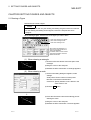
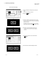
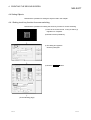
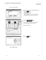
1
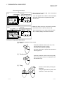
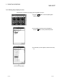
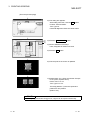
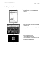
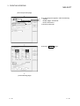
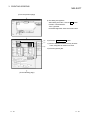
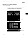
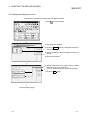
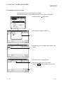
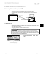
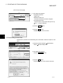
GOT900 Series Operating Manual(Introductory Manual) MITSUBISHI Graphic Operation Terminal • SAFETY PRECAUTIONS • (Always read these instructions before using this equipment.) Before using this product, please read this manual and the relevant manuals introduced in this manual carefully and pay full attention to safety to handle the product correctly. The instructions given in this manual are concerned with this product. For the safety instructions of the programmable controller system, please read the CPU module user's manual. In this manual, the safety instructions are ranked as "WARNING" and "CAUTION". WARNING Indicates that incorrect handling may cause hazardous conditions, resulting in death or severe injury. CAUTION Indicates that incorrect handling may cause hazardous conditions, resulting in medium or slight personal injury or physical damage. Note that the ! CAUTION level may lead to a serious consequence according to the circumstances. Always follow the instructions of both levels because they are important to personal safety. Please save this manual to make it accessible when required and always forward it to the end user. [Test Operation Precautions] ! WARNING • Before performing test operation (bit device on/off, word device's present value changing, timer/counter's set value and present value changing, buffer memory's present value changing) for a user-created monitor screen, read the manual carefully to fully understand how to operate the equipment. During test operation, never change the data of the devices which are used to perform significant operation for the system. False output or malfunction can cause an accident. A-1 A-1 REVISIONS The manual number is given on the bottom left of the back cover. Print Date Aug., 2000 Jun., 2004 Manual Number SH (NA) 080116-A SH (NA) 080116-B Partial corrections Revision SAFETY PRECAUTIONS, About Manuals MODEL CODE change Changed from 13JU07 to 1DM141 Japanese Manual Version SH-080111-B This manual confers no industrial property rights or any rights of any other kind, nor does it confer any patent licenses. Mitsubishi Electric Corporation cannot be held responsible for any problems involving industrial property rights which may occur as a result of using the contents noted in this manual. 2000 MITSUBISHI ELECTRIC CORPORATION A-2 A-2 INTRODUCTION Thank you for choosing the Mitsubishi Graphic Operation Terminal. Before using the equipment, please read this manual carefully to use the equipment to its optimum. CONTENTS About manuals ...............................................................................................................................................A- 8 Abbreviations and generic terms in this manual ...........................................................................................A- 9 CHAPTER1 FUNDAMENTAL KNOWLEDGE 1- 1 to 1- 4 1.1 About GOT ............................................................................................................................................... 11.2 About GOT Operations ............................................................................................................................ 11.3 Mouse Usage and Operations................................................................................................................. 11.4 System Configuration Used in the Manual.............................................................................................. 11.5 Procedures for Use of GOT ..................................................................................................................... 1CHAPTER2 SETTING FIGURES AND OBJECTS 1 2 3 4 4 2- 1 to 2- 2 2.1 Drawing a Figure...................................................................................................................................... 2- 1 2.2 Editing a Figure or Object ........................................................................................................................ 2- 2 CHAPTER3 CREATING SCREENS 3- 1 to 3-15 3.1 Creating a Screen like This...................................................................................................................... 3- 1 3.2 Common Setting before Drawing ............................................................................................................ 3- 2 3.2.1 Selecting GOT/PLC type................................................................................................................... 3- 2 3.2.2 Setting screen switching device........................................................................................................ 3- 3 3.3 Creating the First Screen......................................................................................................................... 3- 4 3.4 Setting Objects ......................................................................................................................................... 3- 5 3.4.1 Setting numerical display function .................................................................................................... 3- 5 3.4.2 Setting numerical input function........................................................................................................ 3- 7 3.4.3 Setting lamp display function ............................................................................................................ 3- 8 3.4.4 Setting touch key function................................................................................................................. 3-11 CHAPTER4 CREATING THE SECOND SCREEN 4- 1 to 4-14 4.1 Creating a Screen like This...................................................................................................................... 4- 1 4.2 Creating the Second Screen.................................................................................................................... 4- 2 4.3 Creating Comments ................................................................................................................................. 4- 3 4.4 Setting Objects ......................................................................................................................................... 4- 4 4.4.1 Setting touch key function for screen switching ............................................................................... 4- 4 4.4.2 Setting level display function............................................................................................................. 4- 7 4.4.3 Setting panelmeter display function.................................................................................................. 4- 9 4.4.4 Setting alarm list display function ..................................................................................................... 4-11 4.5 Saving Created Screen Data................................................................................................................... 4-13 4.6 Reading Saved Screen Data ................................................................................................................... 4-14 A-3 A-3 CHAPTER5 STARTING GOT FOR CHECKING 5- 1 to 5- 6 5.1 Connecting the Personal Computer and GOT........................................................................................ 55.2 Installing the OS....................................................................................................................................... 55.3 Downloading Screen Data ....................................................................................................................... 55.4 Connecting to PLC CPU .......................................................................................................................... 55.5 Executing Monitoring ............................................................................................................................... 55.6 Upload ...................................................................................................................................................... 55.7 Sequence Program Used in the Manual ................................................................................................. 5INDEX A-4 1 1 2 3 4 5 6 Index- 1 A-4 About Manuals The following manuals related to this product are available. Obtain the manuals as required the according to this table. • Related manual Manual name Manual number (Model code) GT Works Version5/GT Designer Version5 Operating Manual (Start up Manual) Describes how to install GT Works Version5/GT Designer Version5 into a personal computer and how to browse the online manuals. IB-0800143 (1DM183) (Found in the packing of the GT Works Version5/GT Designer Version5) GT Works Version5/GT Designer Version5 Reference Manual Deals with the system configuration of GT Works Version5/GT Designer Version5, the screen makeup of the GT Designer, the general description of various monitoring functions, the procedure for displaying the monitor screen on the GOT, and how to use the help function. SH-080117 (1DM187) (Available as option) GT Simulator Version5 Operating Manual Explains the system configuration, screen makeup and using methods of GT Simulator. (Available as option) GOT-A900 Series User’s Manual (GT Works Version5/GT Designer Version5 compatible Connection System Manual) Gives the specifications, system configuration, setting method and connection diagram of each connection form available for the GOT-A900 series. SH-080120 (1DM191) SH-080119 (1DM189) (Available as option) A985GOT/A975GOT/A970GOT/A960GOT User’s Manual Explains the specifications, general system configuration, component devices, part names, option unit loading methods, installation and wiring methods, maintenance and inspection methods, and error codes of A985GOT/A975GOT/A970GOT/A960GOT unit. SH-4005 (1DM099) (Available as option) A950GOT/A951GOT/A953GOT/A956GOT User’s Manual Explains the specifications, general system configuration, component devices, part names, option unit loading methods, installation and wiring methods, maintenance and inspection methods, and error codes of A950GOT/A951GOT/A953GOT/A956GOT unit. SH-080018 (1DM103) (Available as option) GOT-A900 Series Operating Manual (GT Works Version5/GT Designer Version5 compatible Extended • Option Functions Manual) Provides the specifications of the utility, system monitoring, ladder monitoring, special function unit monitoring, network monitoring functions and list editor functions available for the GOT-A900 series and how to operate the dedicated monitor screen. SH-080118 (1DM185) (Available as option) A-5 A-5 Abbreviations and generic terms in this manual Abbreviations and generic terms used in this manual are described as follows: Abbreviations and generic terms A985GOT A975GOT A970GOT A97 GOT A960GOT A956GOT GOT A953GOT A951GOT A951GOT-Q A950GOT A950 handy GOT A95 GOT CommunicaBus connection board tion board GT Works Version5 GT Designer Version5 Software CPU Others A-6 GT Designer GT Simulator GT Converter GT Debugger GT Manager AnUCPU AnACPU AnNCPU ACPU (Large Type) A2US(H)CPU AnS(H)CPU A1SJ(H)CPU ACPU (Small Type) Memory OS Object Personal Computer Description Generic term of A985GOT-TBA, A985GOT-TBD and A985GOT-TBA-EU Generic term of A975GOT-TBA-B, A975GOT-TBD-B, A975GOT-TBA, A975GOT-TBD and A975GOT-TBA-EU Generic term of A970GOT-TBA-B A970GOT-TBD-B, A970GOT-TBA, A970GOT-TBD, A970GOT-SBA, A970GOT-SBD, A970GOT-LBA, A970GOT-LBD, A970GOT-TBA-EU and A970GOT-SBA-EU Generic term of A975GOT and A970GOT Generic term of A960GOT-EBA, A960GOT-EBD and A960GOT-EBA-EU Generic term of A956GOT-TBD, A956GOT-SBD, A956GOT-LBD, A956GOT-TBD-M3, A956GOT-SBD-M3 and A956GOT-LBD-M3 Generic term of A953GOT-TBD, A953GOT-SBD, A953GOT-LBD, A953GOT-TBD-M3, A953GOT-SBD-M3 and A953GOT-LBD-M3 Generic term of A951GOT-TBD, A951GOT-SBD, A951GOT-LBD, A951GOT-TBD-M3, A951GOT-SBD-M3 and A951GOT-LBD-M3 Generic term of A951GOT-QTBD, A951GOT-QSBD, A951GOT-QLBD, A951GOT-QTBD-M3, A951GOT-QSBD-M3 and A951GOT-QLBD-M3 Generic term of A950GOT-TBD, A950GOT-SBD, A950GOT-LBD, A950GOT-TBD-M3, A950GOT-SBD-M3 and A950GOT-LBD-M3 Generic term of A953GOT-SBD-M3-H and A953GOT-LBD-M3-H Generic term of A956GOT, A953GOT, A951GOT, A951GOT-Q, A950GOT and A950 handy GOT Generic term of A9GT-QBUSS, A9GT-QBUS2S, A9GT-BUSS and A9GT-BUS2S SW5D5C-GTWORKS-E software package Generic term of SW5D5C-GOTR-PACKE software package and SW5D5C-GOTR-PACKEV software package Abbreviation of image creation software GT Designer for GOT900 Abbreviation of GT Simulator screen simulator GOT900 Abbreviation of data conversion software GT Converter for GOT900 Abbreviation of debugging software GT Debugger Abbreviation of GT Manager data editing software for GOT900 Generic term of A2UCPU, A2UCPU-S1, A3UCPU and A4UCPU CPU units Generic term of A2ACPU, A2ACPU-S1 and A3ACPU CPU units Generic term of A1NCPU, A2NCPU, A2NCPU-S1 and A3NCPU CPU units Generic term of AnUCPU, AnACPU and AnNCPU CPU units Generic term of A2USCPU, A2USCPU-S1 and A2USHCPU-S1 CPU units Generic term of A1SCPU, A1SHCPU, A2SCPU and A2SHCPU CPU units Generic term of A1SJCPU-S3 and A1SJHCPU CPU units Generic term of A2US(H)CPU, AnS(H)CPU and A1SJ(H)CPU CPU units abbreviation of mmory (flash memory) in the GOT Abreviation of GOT system software Setting data for dynamic image Personal computer where the corresponding software package is installed A-6 1 FUNDAMENTAL KNOWLEDGE MELSOFT CHAPTER1 FUNDAMENTAL KNOWLEDGE 1 This manual describes procedures for creating a simple screen and monitoring with the GOT for learning basic operations. If using the GOT for the first time, read this manual to become familiar with operation of the GOT and the GT Designer. POINT The screen data and sequence programs created in Chapters 3 and 4 of this manual are packed with GT Designer. Use them as required to check settings, for example. 1.1 About GOT (1) What is the GOT? The GOT can be used as an electronic operator panel which has achieved on its monitor screen the switch operation, lamp indication, data display, message display and other operations which were previously performed on an operator panel. Space saving Cost reduction (2) About monitor screen data to be displayed on the GOT The monitor screen data to be displayed on the GOT are created on a personal computer using the dedicated software (GT Designer). You can perform the corresponding functions of the GOT by pasting display frame figures called switch figure, lamp figure, numerical display and other objects to create screens on GT Designer, and setting PLC CPU device memory (bit, word) driven operating functions to the pasted objects. The monitor screen data created are transferred to the GOT through an RS-232C cable or PC card (memory card). PC card RS-232C cable Any of various connection cables Screen data transfer Connection PLC CPU Personal computer GOT 1-1 1-1 1 FUNDAMENTAL KNOWLEDGE MELSOFT 1.2 About GOT Operations This section briefly explains what operations the GOT will perform when it is connected with the PLC CPU. (1) System example PLC CPU Sequence program M0 M1 Y10 Y10 <GOT settings made to figures> Y10 MOV K123 D10 Bus connection cable GOT Touch key setting Bit momentary Write device: M0 Touch key setting Bit momentary Write device: M1 Run Stop Run lamp Lamp display setting Bit Read device: Y10 Data 1 123 Numerical display setting Read device: D10, unsigned BIN Indication: Unsigned decimal (2) Operation explanation (GOT) 1) While the "Run" touch key of the GOT is touched, the bit device "M0" is ON. (PLC CPU) Touch. Turns ON. M0 Run Run lamp Stop M1 Y10 Y10 Y10 MOV K123 D10 Data 0 (PLC CPU) (GOT) Turns ON. Turns ON. M0 Run Run lamp Stop M1 Y10 Y10 2) When the bit device "M0" turns ON, the bit device "Y10" turns ON. An ON figure also appears as the GOT's lamp display where the monitor device is preset to the bit device "Y10". Y10 MOV K123 D10 Data 0 (To the following page) 1-2 1-2 1 1 FUNDAMENTAL KNOWLEDGE MELSOFT (From the previous page) 3) Since the bit device "M0" is ON, "123" is stored into the word device "D10". "123" is stored into D10. (PLC CPU) (GOT) "123" appears. M0 Run Stop Y10 M1 Y10 Run lamp "123" also appears as the GOT's numerical display where the monitor device is preset to the word device "D10". Y10 MOV K123 D10 Data 123 4) While the "Stop" touch key of the GOT is touched, the bit device "M1" of the PLC CPU is ON. M1 turns ON. Y10 turns OFF. (PLC CPU) (GOT) Touch. M0 Run Stop M1 Y10 Since the bit device "Y10" of the PLC CPU turns OFF, the lamp display of the GOT turns OFF. Y10 Run lamp Y10 Display turns OFF. Data MOV K123 D10 123 1.3 Mouse Usage and Operations Describes basic operations of the mouse. (1) Click Press the left button of the mouse once, then release without moving the mouse. This is the most common operation. Using the right button to perform this operation is called "right-click". ck Cli (2) Double click ck Cli ck Cli Press the left button of the mouse twice quickly without moving the mouse. This operation is for the left button only. (3) Drag e us mo n he butto t ve e Mo ile th ed. h w ress p is 1-3 Move the mouse while pressing the left button. Using the right button to perform this operation is called "right-drag". 1-3 1 FUNDAMENTAL KNOWLEDGE MELSOFT 1.4 System Configuration Used in the Manual GT Works Version5 or GT Designer Version5 Install A975GOT Bus connection Data transfer PLC CPU (ACPU) Personal computer 1.5 Procedures for Use of GOT Describes the procedures from installation of the GT Designer to monitoring with the GOT. Start Install the GT Designer. GT Works Version5/GT Designer Version5 Operating Manual (Start up Manual) Start the GT Designer. Carry out common setting. Refer to 3.1 Prepare the user screen data. Refer to Chapter 3 and Chapter 4 Connect the GOT and the personal computer with RS-232C, and turn ON the GOT. Refer to 5.1 Using the GOT for the first time? No Yes Install the OS and the communication driver. Refer to 5.2 Transfer the user screen data. Refer to 5.3 Connect to the PLC, and start monitoring. (Turn OFF the GOT, then turn it ON again.) Refer to 5.4 and 5.5 End 1-4 1-4 2 SETTING FIGURES AND OBJECTS MELSOFT CAHPTER2 SETTING FIGURES AND OBJECTS 2.1 Drawing a Figure Describes how to draw a figure. POINT 2 This chapter deals with only the drawing and editing of figures used in this manual. For the drawing and editing of other figures, refer to the help function of GT Designer. When drawing a figure, click the icon of the figure you want to draw. Click when drawing a rectangle. Click when drawing a scale. Click when entering a text. When setting the attributes of a figure or text, click the list box to choose the attributes. For details, refer to the GT Works Version5/GT Designer Version5 Reference Manual. (1) When drawing a rectangle 1) Click the left mouse button at the start point of the rectangle. 1) 2) 2) Drag the cursor to the end point. 3) 3) Release the left mouse button. A rectangle appears. (2) When drawing a scale 1) As the scale setting dialog box appears, make settings. Scale points: Set the number of scale points. Direction: Choose the scale direction. Center line: Specify whether a line is drawn in the scale center or not. 2) Click the OK button. 3) Press the left mouse button at the starting point of drawing the scale. 3) 4) 5) 4) Drag the cursor to the end point. 5) Release the left mouse button. The scale appears. 2-1 2-1 2 SETTING FIGURES AND OBJECTS MELSOFT (3) When entering a text 1) As the text/figure setting dialog box appears, enter a text. 2) Click the OK button. 2 3) A frame of display range appears at the upper-left of the screen. Move the frame to the desired position. 3) 4) Click the mouse button. The character string appears. 4) 2.2 Editing a Figure or Object (1) Resizing a figure or object The following example enlarges a figure. 1) Select the figure to enlarge. 2) 3) 2) Press the left mouse button at the handle of the selected figure or object ( ) in the direction to enlarge, then drag it. 3) Release the left mouse button. The figure or object is resized. • Holding down the Shift key and changing the size resizes the figure at equal ratios. • Holding down the Ctrl key and changing the size resizes the figure relative to the center. (2) Copying a figure or object The following example copies a figure. 1) Choose the figure to be copied. 2) 3) 2) Hold down the "Ctrl" button of the keyboard and drag the figure. 3) Release the left button of the mouse at the position you want to copy. This copies the figure. 2-2 2-2 3 CREATING SCREENS MELSOFT CHAPTER3 CREATING SCREENS 3.1 Creating a Screen like This In this chapter, a screen as shown below is created. Numerical display function Numerical input function 3 Touch key function Lamp display function 3-1 3-1 3 CREATING SCREENS MELSOFT 3.2 Common Setting before Drawing Describes the operations for common setting before drawing. 3.2.1 Selecting GOT/PLC type Describes the operations for selecting the type of the GOT and the PLC to use. 1) Starting GT Designer displays the project selection dialog box. Click New . 3 2) The dialog box appears. 3) 4) 3) Click the list box and set the type of the GOT and the PLC. Here, set as follows: GOT type: A97 GOT(640 480) PLC type: MELSEC-A 4) Click the OK button. The GOT/PLC types are set. POINT The GOT/PLC type setting dialog box is also displayed by choosing the [Common][GOT/PLC Type] menu. 3-2 3-2 3 CREATING SCREENS MELSOFT 3.2.2 Setting screen switching device Describes the operations for setting the screen switching device for switching screens. Here, only the screen switching device of the base screen is set to "D999" because only the base screens are switched in the manual. 1) Click the [Common] – [Switching Screen] menu. 3) 2) The dialog box appears. 3) Click the Device button on the base screen to set the screen switching device of the base screen. 5) 6) 4) The dialog box appears. 7) 5) Click the list box to set to "D". 6) Click button 9 three times. 7) After setting is completed, click the OK button. (To the following page) 3-3 3-3 3 CREATING SCREENS MELSOFT (From the previous page) 8) Check that value is set to "D999". 8) 9) 9) Click the OK button. The screen switching device is set. POINTS • Screen switching device The screen switching device is required for switching screens. Devices designated as the screen switching devices must be used only as such. Word devices "D" or "W are mainly used as the screen switching device, but device "GD" for the GOT is also available. • Device "GD" Device "GD" is a word device of the GOT. In device GD, 1024 points from GD0 to GD1023 are available. There is a bit device GB, in which 1024 points from GB0 to GB1023 are also available. 3.3 Creating the First Screen Refer to Chapter 2 and create a screen as follows: Use a rectangle to create this. 3-4 Use characters to create these. 3-4 3 CREATING SCREENS MELSOFT 3.4 Setting Objects Describes the operations for setting objects used in this chapter. 3.4.1 Setting numerical display function Describes the operations for setting numerical display function. 1) Click 3) on the tool palette. 2) The dialog box appears. 3) Click the Device button and set the device. Device: Set to D12. 4) 5) 6) 4) Check the check box and click the Shape button to designate the background figure. 5) The dialog box appears. Click the figure to be used as the background. (Here, select figure 21.) 6) Click the OK button. (To the following page) 3-5 3-5 3 CREATING SCREENS MELSOFT (From the previous page) 7) 8) 7) Set the attributes of the figure and numerical value. Here, set as shown on the left. 8) Click the OK button. 9) A frame of display range appears at the upperleft of the screen. Move the frame to the desired position and click. Change the size of the outer figure or the inner object frame with the handle ( ). (Refer to 2.2.) 10) Copy the numerical display function and double-click the copied numerical display function. 11) Change the device to "D13" and click the OK button. 12) This sets two numerical display functions. 3-6 3-6 3 CREATING SCREENS MELSOFT 3.4.2 Setting numerical input function Describes the operations for setting numerical input function. 1) Click 2) 3) 4) on the tool palette. 2) As the dialog box appears, refer to the numerical display function settings and make the following settings. Device: Set to D10. Shape: Use No. 21. 3) Set the attributes of the figure and numerical value. Here set as shown on the left. 4) After setting, click the OK button and place the display range frame of the numerical input function. 5) Copy the numerical input function and change the device of the second numerical input function to "D11". 6) This sets two numerical input functions. POINT In this manual, make setting to display the key window as soon as you touch the part where the numerical input object is set. To make this setting, choose the [Common]-[Auxiliary Setting]-[Project] menu and turn on the "When touch input is detected, open key window at the same time" check box. 3-7 3-7 3 CREATING SCREENS MELSOFT 3.4.3 Setting lamp display function Describes the operations for setting the lamp display function. 1) Click the List button on the template (parts display area). 2) The template (directory tree) is displayed. Click the + button of the parts library folder. 3) As the library names appear, double-click Lamp (1). (To the following page) 3-8 3-8 3 CREATING SCREENS MELSOFT (From the previous page) 4) Parts in the library are displayed on the template (part display area). 5) Click a lamp on the template (part display area). (Here, use No. 1). 6) Move the cursor to the screen. A frame of display range appears. Move the frame to the desired position and click. 7) Double-click the pasted lamp. 8) The dialog box appears. 9) 9) Click the Device button and set the device. Device: Set to Y0. 10) 10) After setting the device, click the Case (Bit) tab. 11) Click the Text button. (To the following page) 3-9 3-9 3 CREATING SCREENS MELSOFT (From the previous page) 12) The dialog box appears. After setting each item, click the OK button. Position: Choose Bottom. Text: Type Y0. Horizontal alignment: Click the center button. 13) 14) 15) 13) Click the Copy from ON button. 14) Set the attributes of the lamp. Here, designate as shown on the left. 15) Click the OK button. 16) The lamp set on the screen is updated. 17) Repeat steps 7) to 16) for the number of lamps to set. (Here, repeat 3 times.) Device: Set Y1 to Y3. Text: Type Y1 to Y3. The lamp pasted in 7) must be copied and pasted to a new position. (Refer to 2.2.) POINT With the [Edit]-[Consecutive Copy] menu, a figure can be copied continuously. 3 - 10 3 - 10 3 CREATING SCREENS MELSOFT 3.4.4 Setting touch key function Describes the operations for setting touch key function. 1) Double-click Switch (1) on Template (directory tree) only. Refer to Section 3.4.3 for the way to display Template (directory tree). 2) Parts in the library are displayed on the template (part display area). 3) Click a lamp on the template (part display area). Here, use No.16. 4) Move the cursor to the screen. A frame of display range appears. Move the frame to the desired position and click. 5) Double-click the pasted touch key. (To the following page) 3 - 11 3 - 11 3 CREATING SCREENS MELSOFT (From the previous page) 6) 7) 6) As the dialog box appears, make the following settings. Display trigger: Choose Bit. Device: Set to M70. 7) Click the [Case] tab. 8) Click the ON Text button. (To the following page) 3 - 12 3 - 12 3 CREATING SCREENS MELSOFT (From the previous page) 9) The dialog box appears. After setting each item, click the OK button. Position: Choose Bottom. Text: Type M70. Horizontal alignment: Click the center button. 10) 11) 12) 10) Click the Copy from ON button. 11) Set the attributes of the touch key and text. Here, designate as shown on the left. 12) Click the [Action] tab. (To the following page) 3 - 13 3 - 13 3 CREATING SCREENS MELSOFT (From the previous page) 13) Click the Bit button. 14) 15) 16) 14) The dialog box appears. Select "Alternate". 15) Click the Device button and set the device to "M70". 16) Click the OK button. (To the following page) 3 - 14 3 - 14 3 CREATING SCREENS MELSOFT (From the previous page) 17) Click the OK button. 18) The touch key set on the screen is updated. 19) Repeat steps 5) to 18) for the number of touch keys to set. (Here, repeat 3 times.) Device: Set M71 to M73. Text: Type M71 to M73. The key pasted before step 5) must be copied and pasted to a new position. (Refer to 2.2.) POINT With the [Edit]-[Continuous Copy] menu, a figure can be copied continuously. 3 - 15 3 - 15 4 CREATING THE SECOND SCREEN MELSOFT CHAPTER4 CREATING THE SECOND SCREEN 4.1 Creating a Screen like This In this chapter, the following screen is created as the second screen of the screen created in Chapter 3 (the first screen). The switching button to the second screen is added to the first screen. (1) Adding the screen switching button to the first screen The screen switching button to the second screen must be set on the first screen. Set a touch key at the lower right corner of the first screen. 4 Touch key function (2) Creating the second screen Level display function Parameter display function Alarm list display function Touch key function 4-1 4-1 4 CREATING THE SECOND SCREEN MELSOFT 4.2 Creating the Second Screen Describes the operations for creating the second screen. 1) Click on tool bar 1. 2) Click the spin box and set the screen number to "2". 2) 3) 3) Click the OK button. The second screen is created. 4 First, create a screen as follows by referring to Chapter 2. Use rectangles to create these. Use scales to create these. 4-2 4-2 4 CREATING THE SECOND SCREEN MELSOFT 4.3 Creating Comments Describes the operations for creating comments that are used in the alarm list function. Register comments as follows: Comment No. Device Comment 1 Y0 A-line supply conveyer stopped. Check the power source. 2 Y1 Emergency stop limit switch operated. Check the product. 3 Y2 4 Y3 Product limit switch does not operate. Check for presence/absence of the product. Hydraulic pressure of finishing machine 1 is low. Supply hydraulic oil. 1) Click the [Draw]-[Comment] menu. 2) As the dialog box appears, type a comment from the keyboard. 3) After comment creation, click the Enter button to register the No. 1 comment. 2) 3) 4) 5) 4) Create remaining No. 2 to No. 4 comments. 5) After setting is completed, click the OK button. The dialog box disappears. 4-3 4-3 4 CREATING THE SECOND SCREEN MELSOFT 4.4 Setting Objects Describes the operation for setting the objects used in this chapter. 4.4.1 Setting touch key function for screen switching Describes the operations for setting the touch key function for screen switching. 1) Paste to the screen the No. 15 key of Switch (1) registered on Template. 2) Double-click the pasted key. 3) The dialog box appears. Click the [Case] tab. 4) Click the ON Text button. (To the following page) 4-4 4-4 4 CREATING THE SECOND SCREEN MELSOFT (From the previous page) 5) The dialog box appears. After setting each item, click the OK button. Position: Select Center. Text: Input Screen 1. Horizontal alignment: Click the center button. Vertical alignment: Click the center button. 6) 7) 6) Click the Copy from ON button. 7) Set the attributes of the touch key and text. Here, designate as shown on the left. 8) 8) Click the [Action] tab. 9) Click the Base button. (To the following page) 4-5 4-5 4 CREATING THE SECOND SCREEN MELSOFT (From the previous page) 10) 11) 10) The dialog box appears. Designate the destination to "Fixed". 12) 11) Click the spin box and input "Screen 2" for the touch key set on the first screen and "Screen 1" for the touch key set on the second screen. 12) Click the OK button. 13) Click the OK button. 14) The touch key set on the screen is updated. 15) Change the key size with the handle ( ). (Refer to 2.2.) POINT When setting the screen changing switch on the first screen, choose [Screen]-[B-1 No title] to display the first screen, and set the screen changing switch in the above procedure. Displays the base screen 1. Displays the base screen 2. 4-6 4-6 4 CREATING THE SECOND SCREEN MELSOFT 4.4.2 Setting level display function Describes the operations for setting the level display function. 1) Click on the tool pallet. 2) The dialog box appears. 3) 3) Click the Device button to designate the device. Device: Set to D12. 4) 4) Set the attributes of the level display as shown on the left. 5) 5) Click the [Form] tab. 6) Set the Fixed value of the Upper value to "10000" and that of the Lower value to "0". (You can type them directly from the keyboard.) 7) 6) 7) Click the OK button. (To the following page) 4-7 4-7 4 CREATING THE SECOND SCREEN MELSOFT (From the previous page) 8) A frame of display range appears at the upper-left of the screen. Move the frame to the desired position, then click. 9) Change the key size with the handle ( ). (Refer to 2.2.) 11) Copy the level display function and set the device of the second level display function to "D13". 12) This sets two level display functions. 4-8 4-8 4 CREATING THE SECOND SCREEN MELSOFT 4.4.3 Setting panelmeter display function Describes the operations for setting the panelmeter display function. 1) Click on the tool palette. 2) As the dialog box appears, refer to the level display function settings and make the following settings. Device: Set to D12. Shape: Use No. 39. 2) 3) Set the attributes of the panelmeter. Make settings as shown on the left. 3) 4) 4) Click the [Form] tab. 5) Make the [Form] tab settings as indicated below. Type: Top 1/2 5) Upper: Fixed, 10000 Lower: Fixed, 0 6) 6) After setting, click the Extended>> button. (To the following page) 4-9 4-9 4 CREATING THE SECOND SCREEN MELSOFT (From the previous page) 7) Click the [Graph] tab. 8) Make the [Graph] tab settings as indicated below. Upper: Fixed, 100 8) Lower: Fixed, 0 9) 9) Click the OK button. 10) A frame of display range appears at the upper-left of the screen. Move the frame to the desired position, then click. 11) Using the handles ( ), set the size. (Refer to 2.2.) 12) Copy the panelmeter display function and change the device of the second panelmeter display function to "D13". 13) This sets two panelmeter display functions. 4 - 10 4 - 10 4 CREATING THE SECOND SCREEN MELSOFT 4.4.4 Setting alarm list display function Describes the operations for setting the alarm list display function. 1) Click on the tool palette. 2) The dialog box appears. 3) Check the check box and click the Shape button to designate the background figure. (Here, select figure 39.) 3) 4) 5) 4) Set the attributes of the figure. Make settings as shown on the left. 5) Click the [Form] tab. 6) Click the spin box and set the device value to "4". 6) 7) Click the Device button. 7) (To the following page) 4 - 11 4 - 11 4 CREATING THE SECOND SCREEN MELSOFT (From the previous page) 8) 9) 10) 8) The dialog box appears. Click the Edit button to set the device. Device: Set Y0. 9) Select "Continuous". 10) Click the OK button. 11) 11) Set the number of comments to display to "Single". 12) Click the OK button. 12) 13) A frame of display range appears at the upper-left of the screen. Move the frame to the desired position, then click. 14) Change the size with the handle ( ). (Refer to 2.2.) 4 - 12 4 - 12 4 CREATING THE SECOND SCREEN MELSOFT 4.5 Saving Created Screen Data Describes the operations for saving created screen data. Here, the data is saved on a personal computer's hard disk (drive C) as an example. 1) Click [Project] [Save As]. 2) The dialog box appears. Click the list box and click "(C:)". 2) 3) 3) Click the folder creation button to create a new folder. 4) Designate a project name to the new folder. (Here, input "Got".) 5) After designating the name, double-click "Got" and display the contents of the folder. 6) Check that "Got" is displayed here. 6) 7) Click the Save button to save the screen data. 7) POINT When saving screen data, create a folder for each project. Note that since the file name of GT Designer is fixed, the project of GT Designer already existing in the folder where a new project will be saved will be overwritten by the new project. 4 - 13 4 - 13 4 CREATING THE SECOND SCREEN MELSOFT 4.6 Reading Saved Screen Data Describes the operations for reading the saved data. Here,the data saved in 4.5 (the data saved in drive C) is read as an example. 1) Click the [Project] [Open] menu. 2) The dialog box appears. Click "(C:)". 2) 3) Double-click "Got" and display the contents of the folder. 3) 4) Check that "Got" is displayed here. 4) 5) Check that "a9gotp.got" is in the folder. Click the Open button to read the screen data. 5) 4 - 14 4 - 14 5 STARTING GOT FOR CHECKING MELSOFT CHAPTER5 STARTING GOT FOR CHECKING 5.1 Connecting the Personal Computer and GOT Connect the personal computer and the GOT with an RS-232C cable. For further details, refer to GT Works Version5/GT Designer Version5 Reference Manual. RS-232C interface COM port RS-232C cable A975GOT Personal computer 5.2 Installing the OS Describes the operations for installing the OS program and the communication driver on the GOT before monitoring. This chapter describes a specific installation example. POINT The GOT does not have the OS program for monitoring or the communication driver. Therefore, these programs must be installed on the GOT before monitoring. Once the programs are installed, you do not need to install again unless the version of OS or the communication method changes. 1) Click the [Communication] menu. [Install] [OS] (To the following page) 5-1 5-1 5 5 STARTING GOT FOR CHECKING MELSOFT (From the previous page) 2) 3) 2) The dialog box appears. Designate each item. Target: GOT Standard monitor OS: Check the checkbox and select "English". Communication driver: Click the list box, then select "Bus [Ver 8.0.0]. [Ver *.*.*] may be different. 3) Click the Install button. 4) Click the Yes button. Installation of the OS is executed. 5 5.3 Downloading Screen Data Describes the operations for downloading the screen data created in Chapter 4 to the GOT. 1) Click the [Communication] [Download (to GOT)] [Monitor Data] menu. 2) The dialog box appears. Click the Download button. 3) Click the OK button. Downloading of the screen data is executed. 5-2 5-2 5 STARTING GOT FOR CHECKING MELSOFT 5.4 Connecting to PLC CPU Here, the bus connection is used to connect the GOT and the PLC CPU. For details of the bus connection board and the bus connection cable, refer to GOT-A900 Series User′s Manual (GT Works Version5/GT Designer Version5 compatible Connection System Manual). Bus communication board Set the extension number switch to 1. Set the I/O slot switch to 0. A975GOT Bus communication cable PLC CPU (ACPU) POINT Be sure to turn OFF the whole system before connecting the GOT and the PLC CPU. 5-3 5-3 5 STARTING GOT FOR CHECKING MELSOFT 5.5 Executing Monitoring Displays numerical values for D12 and D13. Input values to D10 and D11 from the ten-key window. When the external input Y0 to Y3 are turned ON, the lamp lights accordingly. Press the touch key. The corresponding external output M70 to M73 is turned ON/OFF. Press the touch key. The second screen appears. Carries out level display of values D12 and D13. Carries out panel meter display of values D12 and D13. Turning ON of Y0 to Y3 displays the designated alarm comments. Press the touch key. The first screen appears. 5-4 5-4 5 STARTING GOT FOR CHECKING MELSOFT 5.6 Upload When you want to make correction to the screen data installed into the GOT, use GT Designer and read the screen data from the GOT to the personal computer. The read screen data can be re-edited and then re-transferred (downloaded) to the GOT. This section describes the operation to upload data from the GOT to the personal computer. 1) Click the [Communication] GOT)] menu. [Upload (from 2) As the dialog box appears, specify "Upload destination path:" (drive or folder) and click the Upload button. 3) Click the Yes button. Uploading of the screen data is executed. 5-5 5-5 5 STARTING GOT FOR CHECKING MELSOFT 5.7 Sequence Program Used in the Manual 5-6 5-6 INDEX Ind [A] About GOT ..................................................... 1- 1 Alarm list display function.............................. 4-11 [C] Click ................................................................ 1- 3 Comment ........................................................ 4- 3 Common ......................................................... 3- 2 Communication driver .................................... 5- 2 Connecting the personal computer and GOT ........................................................................ 5- 1 Connecting to PLC CPU ................................ 5- 3 Consecutive copy.......................................... 3-10 Copy................................................................ 2- 2 [D] Double click .................................................... 1- 3 Download........................................................ 5- 2 Drag ................................................................ 1- 3 Drawing figures .............................................. 2- 1 [N] Numerical display function..............................3- 5 Numerical input function .................................3- 7 [O] Open...............................................................4-14 [P] Panelmeter display function ...........................4- 9 Procedures for use of GOT ............................1- 4 [R] Rectangle ........................................................2- 1 Resizing...........................................................2- 2 [S] Save ...............................................................4-13 Scale................................................................2- 1 Screen switching device .................................3- 3 [T] [E] Editing figures................................................. 2- 2 Editing objects ................................................ 2- 2 [G] GOT operations.............................................. 1- 2 GOT/PLC Type............................................... 3- 2 Text..................................................................2- 2 Touch key function for screen switching ........4- 4 Touch key function.........................................3-11 [U] Upload .............................................................5- 5 [H] Handle ............................................................ 2- 2 [I] Installing the OS ............................................. 5- 1 [L] Lamp display function .................................... 3- 8 Level display function..................................... 4- 7 [M] Mouse ............................................................. 1- 3 Index - 1 Index - 1 WARRANTY Please confirm the following product warranty details before starting use. 1. Gratis Warranty Term and Gratis Warranty Range If any faults or defects (hereinafter "Failure") found to be the responsibility of Mitsubishi occurs during use of the product within the gratis warranty term, the product shall be repaired at no cost via the dealer or Mitsubishi Service Company. Note that if repairs are required at a site overseas, on a detached island or remote place, expenses to dispatch an engineer shall be charged for. [Gratis Warranty Term] The gratis warranty term of the product shall be for one year after the date of purchase or delivery to a designated place. Note that after manufacture and shipment from Mitsubishi, the maximum distribution period shall be six (6) months, and the longest gratis warranty term after manufacturing shall be eighteen (18) months. The gratis warranty term of repair parts shall not exceed the gratis warranty term before repairs. [Gratis Warranty Range] (1) The range shall be limited to normal use within the usage state, usage methods and usage environment, etc., which follow the conditions and precautions, etc., given in the instruction manual, user's manual and caution labels on the product. (2) Even within the gratis warranty term, repairs shall be charged for in the following cases. 1. Failure occurring from inappropriate storage or handling, carelessness or negligence by the user. Failure caused by the user's hardware or software design. 2. Failure caused by unapproved modifications, etc., to the product by the user. 3. When the Mitsubishi product is assembled into a user's device, Failure that could have been avoided if functions or structures, judged as necessary in the legal safety measures the user's device is subject to or as necessary by industry standards, had been provided. 4. Failure that could have been avoided if consumable parts (battery, backlight, fuse, etc.) designated in the instruction manual had been correctly serviced or replaced. 5. Failure caused by external irresistible forces such as fires or abnormal voltages, and Failure caused by force majeure such as earthquakes, lightning, wind and water damage. 6. Failure caused by reasons unpredictable by scientific technology standards at time of shipment from Mitsubishi. 7. Any other failure found not to be the responsibility of Mitsubishi or the user. 2. Onerous repair term after discontinuation of production (1) Mitsubishi shall accept onerous product repairs for seven (7) years after production of the product is discontinued. Discontinuation of production shall be notified with Mitsubishi Technical Bulletins, etc. (2) Product supply (including repair parts) is not possible after production is discontinued. 3. Overseas service Overseas, repairs shall be accepted by Mitsubishi's local overseas FA Center. Note that the repair conditions at each FA Center may differ. 4. Exclusion of chance loss and secondary loss from warranty liability Regardless of the gratis warranty term, Mitsubishi shall not be liable for compensation to damages caused by any cause found not to be the responsibility of Mitsubishi, chance losses, lost profits incurred to the user by Failures of Mitsubishi products, damages and secondary damages caused from special reasons regardless of Mitsubishi's expectations, compensation for accidents, and compensation for damages to products other than Mitsubishi products and other duties. 5. Changes in product specifications The specifications given in the catalogs, manuals or technical documents are subject to change without prior notice. 6. Product application (1) In using the Mitsubishi MELSEC programmable logic controller, the usage conditions shall be that the application will not lead to a major accident even if any problem or fault should occur in the programmable logic controller device, and that backup and fail-safe functions are systematically provided outside of the device for any problem or fault. (2) The Mitsubishi general-purpose programmable logic controller has been designed and manufactured for applications in general industries, etc. Thus, applications in which the public could be affected such as in nuclear power plants and other power plants operated by respective power companies, and applications in which a special quality assurance system is required, such as for Railway companies or National Defense purposes shall be excluded from the programmable logic controller applications. Note that even with these applications, if the user approves that the application is to be limited and a special quality is not required, application shall be possible. When considering use in aircraft, medical applications, railways, incineration and fuel devices, manned transport devices, equipment for recreation and amusement, and safety devices, in which human life or assets could be greatly affected and for which a particularly high reliability is required in terms of safety and control system, please consult with Mitsubishi and discuss the required specifications. GOT900 Series GOT900 Series Operating Manual(Introductory Manual) Operating Manual(Introductory Manual) MODEL GOT900-O(NYU)-E MODEL CODE 1DM141 SH(NA)-080116-B(0406)MEE HEAD OFFICE : 1-8-12, OFFICE TOWER Z 14F HARUMI CHUO-KU 104-6212,JAPAN NAGOYA WORKS : 1-14 , YADA-MINAMI 5-CHOME , HIGASHI-KU, NAGOYA , JAPAN When exported from Japan, this manual does not require application to the Ministry of Economy, Trade and Industry for service transaction permission. Specifications subject to change without notice. MITSUBISHI Graphic Operation Terminal