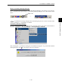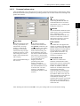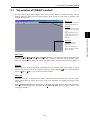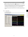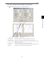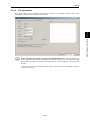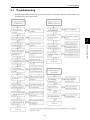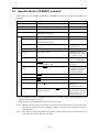
1
Inverter Support Software FRENIC Loader2 Instruction Manual INR-SI47-1185-E Copyright © 2007 Fuji Electric FA Components & Systems Co., Ltd. No part of this publication may be reproduced or copied without prior written permission from Fuji Electric FA Components & Systems Co., Ltd. All products and company names mentioned in this manual are trademarks or registered trademarks of their respective holders. The information contained herein is subject to change without prior notice for improvement. Preface Thank you for using FRENIC Loader2 This manual provides all the information you will need on Fuji’s inverter support utility tool, FRENIC Loader2 and the related communication protocols and devices supporting its operations. Read this manual carefully for correct use of Loader. This manual, however, does not contain information on the RS-485 communications card (option for FRENIC-Mini) or the FRENIC-Mini/Eco/Multi series of inverters. For details on these products, refer to the publications listed below. The table below lists other material related to the use of the FRENIC-Mini/Eco/Multi. Read them in conjunction with technical documents related to Fuji's inverters. User’s Manuals and Instruction Manuals RS-485 Communication User’s Manual FRENIC-Mini User’s Manual FRENIC-Mini Instruction Manual RS-485 Communications Card "OPC-C1-RS" Installation Manual FRENIC-Eco USER’S MANUAL FRENIC-Eco Instruction Manual FRENIC-Multi USER’S MANUAL FRENIC-Multi Instruction Manual MEH448 MEH446 INR-S147-0791-E INR-SI47-0773 MEH456 INR-S147-0882-E MEH457 INR-SI47-1094-E Safety Precautions Read this manual thoroughly before proceeding with installation, connections (wiring), or operation. Ensure you have sound knowledge of the device and software and have familiarized yourself with all safety information and precautions before proceeding to operate the inverter via FRENIC Loader2. Safety precautions are classified into the following two categories in this manual. Failure to heed the information indicated by this symbol may result in death or serious injury. Failure to heed the information indicated by this symbol may result in minor or light injury and/or substantial property damage. Wiring and Connection of Cables • Be sure to perform all wiring and cable connections after turning off the power to the inverters and all related devices. Risk of electric shock if this warning is not heeded. • Do not connect an RS-485 communications cable to the RS232C serial COM port without using an RS232C-RS-485 communications level converter. An accident could occur if this warning is not heeded. • If you connect an RS-485 communications cable to the RS-485 ports, ensure the pin assignment of device port has been performed correctly. For details, refer to Chapter 1, Section 1.2 "Connecting inverters to a PC." An accident or mechanical failure could occur if this warning is not heeded. Operation • If you have reset the alarm while any run commands is turned on, the inverter may cause the motor to run unexpectedly. An accident or injury could occur if this warning is not heeded. i Summary of Contents Preface .....................................................................................................................................i Safety Precautions ..............................................................................................................i Summary of Contents ............................................................................................................ii Chapter 1 Before Using FRENIC Loader2 ........................................................................1-1 1.1 Overview....................................................................................................................................................... 1-1 1.1.1 Features................................................................................................................................................ 1-1 1.1.2 Loader functions ................................................................................................................................... 1-1 1.1.3 Warranty ............................................................................................................................................... 1-2 1.2 Connecting inverters to a PC........................................................................................................................ 1-2 1.2.1 Configuring an RS-485 communications network ................................................................................. 1-2 1.2.2 Example of networking ......................................................................................................................... 1-3 1.2.3 Pin assignment for RS-485 communications port ................................................................................. 1-4 1.2.4 Communications support devices ......................................................................................................... 1-5 [ 1 ] Communications level converter................................................................................................. 1-5 [ 2 ] Requirements for the cable......................................................................................................... 1-6 [ 3 ] Multi-drop adapter....................................................................................................................... 1-6 [ 4 ] RS-485 communications card (Option for FRENIC-Mini)............................................................ 1-6 1.2.5 Noise suppression ................................................................................................................................ 1-6 1.3 Installation of FRENIC Loader2 .................................................................................................................... 1-7 1.3.1 Installation............................................................................................................................................. 1-7 1.3.2 Uninstalling Loader ............................................................................................................................. 1-12 1.4 Settings Before Starting FRENIC Loader2 ................................................................................................. 1-14 1.4.1 Function codes setup in the inverter ................................................................................................... 1-14 1.4.2 Checking the COM port in the PC....................................................................................................... 1-14 1.4.3 Settings on Loader.............................................................................................................................. 1-16 1.4.3.1 Communications setup ............................................................................................................... 1-17 1.4.3.2 Connection setup ........................................................................................................................ 1-18 Chapter 2 Functions of FRENIC Loader2.........................................................................2-1 2.1 Top window of FRENIC Loader2 .................................................................................................................. 2-1 2.2 File................................................................................................................................................................ 2-2 2.2.1 New ...................................................................................................................................................... 2-2 2.2.2 Open ..................................................................................................................................................... 2-2 2.2.3 Print Setup ............................................................................................................................................ 2-3 2.2.4 Exit........................................................................................................................................................ 2-3 2.3 Menu............................................................................................................................................................. 2-4 2.3.1 Real-time trace—Displaying running status of an inverter in waveforms .............................................. 2-4 2.3.1.1 Sub-windows ................................................................................................................................ 2-5 [ 1 ] Measuring monitor ...................................................................................................................... 2-5 [ 2 ] Positioning graphs ...................................................................................................................... 2-6 2.3.1.2 Channel configuration ................................................................................................................... 2-6 2.3.1.3 Real-time trace—Advanced setup of analog channels ................................................................. 2-7 2.3.1.4 Real-time trace—Advanced setup of digital channels................................................................... 2-8 2.3.1.5 Real-time trace—Advanced setup of reconfirming the channel setup......................................... 2-10 2.3.1.6 Real-time trace—Other advanced settings ................................................................................. 2-10 2.3.2 Multi-monitor ....................................................................................................................................... 2-11 [ 1 ] Adding/deleting the listed items .................................................................................................2-11 2.3.3 Operation monitor ............................................................................................................................... 2-13 2.3.3.1 I/O monitor—Monitor for control input/output signal status of the inverter .................................. 2-13 2.3.3.2 System monitor ........................................................................................................................... 2-13 2.3.3.3 Alarm monitor.............................................................................................................................. 2-14 2.3.3.4 Meter display .............................................................................................................................. 2-15 [ 1 ] How to setup information to be monitored ................................................................................ 2-16 [ 2 ] How to setup the advanced settings for analog meters ............................................................ 2-17 ii Chapter 3 Reference Information......................................................................................3-1 3.1 Troubleshooting ............................................................................................................................................ 3-1 3.2 Specifications of FRENIC Loader2 ............................................................................................................... 3-2 iii Chap. 1 Chap. 2 Chap. 3 2.3.4 Setting function code data .................................................................................................................. 2-18 2.3.4.1 Function code edit....................................................................................................................... 2-19 [ 1 ] Read function code data stored in the inverter ......................................................................... 2-20 [ 2 ] How to change the function code data...................................................................................... 2-22 [ 3 ] Writing the function code data into the inverter from Loader..................................................... 2-23 [ 4 ] Writing function codes in to inverters whose rated power inputs or capacities are different each other…...................................................................................................................................... 2-23 [ 5 ] Saving function code data in the PC......................................................................................... 2-24 [ 6 ] Initializing the function code data stored in an inverter ............................................................. 2-24 [ 7 ] Printing the function code data list ............................................................................................ 2-25 2.3.4.2 Auto-tuning motor parameters .................................................................................................... 2-26 2.3.4.3 Comparing the function codes .................................................................................................... 2-27 2.3.4.4 Searching a function code by a character string ......................................................................... 2-28 2.3.4.5 File information ........................................................................................................................... 2-29 2.3.5 Test-running........................................................................................................................................ 2-30 2.3.5.1 How to setup the inverter and run the motor using Loader ......................................................... 2-31 2.3.5.2 How to recover Loader whose test-run window cannot monitor inverter status .......................... 2-33 2.3.6 Quick access menu ............................................................................................................................ 2-35 2.3.7 Option ................................................................................................................................................. 2-35 2.4 View............................................................................................................................................................ 2-36 2.4.1 Toolbar................................................................................................................................................ 2-36 2.4.2 Status bar ........................................................................................................................................... 2-36 2.5 Window....................................................................................................................................................... 2-37 2.5.1 Cascade windows............................................................................................................................... 2-37 2.5.2 Tile windows ....................................................................................................................................... 2-37 2.5.3 Tile vertically windows ........................................................................................................................ 2-38 2.5.4 Arrange icons...................................................................................................................................... 2-38 2.6 Help ............................................................................................................................................................ 2-39 2.6.1 About FRENIC Loader2 ...................................................................................................................... 2-39 Chapter 1 Before Using FRENIC Loader2 This chapter gives you an overview of the inverter support loader software, FRENIC Loader2, and provisions for its installation and operation. Contents 1.1 Overview....................................................................................................................................................... 1-1 1.1.1 Features................................................................................................................................................ 1-1 1.1.2 Loader functions ................................................................................................................................... 1-1 1.1.3 Warranty ............................................................................................................................................... 1-2 1.2 Connecting inverters to a PC........................................................................................................................ 1-2 1.2.1 Configuring an RS-485 communications network ................................................................................. 1-2 1.2.2 Example of networking ......................................................................................................................... 1-3 1.2.3 Pin assignment for RS-485 communications port ................................................................................. 1-4 1.2.4 Communications support devices ......................................................................................................... 1-5 [ 1 ] Communications level converter................................................................................................. 1-5 [ 2 ] Requirements for the cable......................................................................................................... 1-6 [ 3 ] Multi-drop adapter....................................................................................................................... 1-6 [ 4 ] RS-485 communications card (Option for FRENIC-Mini)............................................................ 1-6 1.2.5 Noise suppression ................................................................................................................................ 1-6 1.3 Installation of FRENIC Loader2 .................................................................................................................... 1-7 1.3.1 Installation............................................................................................................................................. 1-7 1.3.2 Uninstalling Loader ............................................................................................................................. 1-12 1.4 Settings Before Starting FRENIC Loader2 ................................................................................................. 1-14 1.4.1 Function codes setup in the inverter ................................................................................................... 1-14 1.4.2 Checking the COM port in the PC....................................................................................................... 1-14 1.4.3 Settings on Loader.............................................................................................................................. 1-16 1.4.3.1 Communications setup ............................................................................................................... 1-17 1.4.3.2 Connection setup ........................................................................................................................ 1-18 1.1 Features 1.1 Overview 1.1.1 Features • Loader functions The table below provides an overview of FRENIC Loader2 functions. Function Overview Shows operation status of inverters real-time in graph chart format with data lists. Multi-monitor Lists the operation status of inverter(s). Operation Status Monitor Real-time trace I/O monitor Indicates the I/O terminal status of the selected inverter. System monitor Indicates the inverter ROM version, maintenance information and etc. Alarm monitor Indicates the inverter status during alarm mode. Meter display Indicates the inverter running status in analog meter format. Allows you to edit, compare or set the function code data and edit the file information while viewing a list of them. The function code files listed and edited in the Function code edit window are one of the following: - Newly created. - Read data set in the inverter. - Read data stored in the PC. Function code settings Function code edit Displaying Function codes Shows the function codes by category--all, in groups (F, E, C or etc.), those whose data settings differ from factory defaults, those selected by the user to show, communications codes, results of comparison, or searching result of the function codes. Writing the changed data Edits the function code data read from the inverter and overwrites new function code data to the inverter. Writing data changed from factory defaults Overwrites only the function code data changed from those set in the inverter as factory defaults. Writing all Overwrites all data to the inverter unconditionally. Help (information on function codes) Shows the meaning of function code data for each code. Saving data Saves the function code data currently listed in the file. Printing data Prints the list of function codes. Initialization Initializes all function code data set in the inverter(s) managed by Loader or currently being edited by Loader. Auto-tuning motors Obtains motor parameters (%R, %X, no load current I0 and Rated slip) and save them in the inverter. Comparison Compares the editing code data with those saved in the selected file or set in the selected inverter. File information Displays and sets information such as model and comments related to the file used to save the function code data. Test run Enables the user to run/stop the inverter or set the frequency command and the terminal assignment, and shows the output frequency, drive current and status of programmable I/O terminals. 1-1 Before Using FRENIC Loader 1.1.2 Chap. 1 FRENIC-Loader2 enables a PC to support remote operation of inverters either individually or together via the RS-485 communications port on the inverter. • Simplified operation of Loader allows you to easily run/stop the motor, monitor operation status of the inverter, and to manage and set the function code data for the inverter. • Real-time trace allows you to monitor operation status of the inverters real-time in a graph chart format with data lists, and to save the monitored result in a file that is useful to analyze operation of a system configured with inverters. 1.1.3 Warranty Limited Warranty In no event will FUJI Electric be held liable for any damage (including, but not limited to lost profit, suspension or interruption of operations, loss of operational data or other monetary loss) whatsoever resulting from the use of the software or malfunction of the same or from information contained in this document. 1.2 Connecting inverters to a PC 1.2.1 Configuring an RS-485 communications network To configure a network connecting inverters and a PC to run FRENIC Loader2, the inverters require the optional RS-485 communications card and the PC equipped with an RS232C-RS-485 converter or a USB-RS-485 converter. • Be sure to perform all wiring and cable connections after turning off the power to the inverters and all related devices. Risk of electric shock if this warning is not heeded. • Do not connect an RS-485 communications cable to the RS232C serial COM port without using an RS232C-RS-485 communications level converter. An accident could occur if this warning is not heeded. • If you connect an RS-485 communications cable to the RS-485 ports, ensure the pin assignment of device port has been performed correctly. For details, refer to Section 1.2.3 "Pin assignment for RS-485 communications port." An accident or mechanical failure could occur if this warning is not heeded. 1) To minimize the effects of noise separate the signal lines from the power lines. Refer to Subsection 1.2.5 "Noise suppression." 2) You cannot use FRENIC Loader2 and other hosting equipment such as a PLC or an additional PC concurrently. To use Loader, disconnect the cables of any such equipment from the RS-485 port on the inverter. 3) Assign different station addresses to each of the inverters connected. 1-2 1.2 Connecting inverters to a PC 1.2.2 Example of networking The block diagram shown below is of a configuration example for FRENIC Loader2 using a multi-drop adapter and RS-485 communications network. Multi-drop network using RJ-45 connectors Chap. 1 FRENIC-Multi Figure 1.1 RS-485 Multi-drop Network using RJ-45 Connectors • RJ-45 connectors mounted in the inverter and on the RS-485 communications card, have pins assigned for feeding power to the keypad used for remote operations. Do not use these pins for any other purposes such as for connection of any equipment other than the keypad. (See Figure 1.2 and Figure 1.3 on the next page.) • Before preparing parts or devices, to protect parts on the printed circuit board(s) of inverters from damages due to lightening shock, or to keep the network in high noise immunity level, carefully read through the descriptions in Section 1.2.4 "Communications support devices." • The maximum cable length on the RS-485 communications network is 500m. • Termination resistors of stations at ends of the network should be turned on and ones of others off. 1-3 Before Using FRENIC Loader2 FRENIC Loader2 1.2.3 Pin assignment for RS-485 communications port For ease of connection to a standard RS232C-RS-485 communications converter FRENIC-Mini/Eco/Multi is designed to be compliant with the standard 4 pairs signal line pin assignment for the RJ-45 connector, where a pair of signal lines DX- and DX+ are assigned to No. 4 and 5 pins as shown in Figure 1.2. The power feed lines to the keypad occupy No. 1, 2, 7 and 8 pins. Do not use these pins to connect equipment other than the keypad through this connector, especially be careful for No. 1 and 7 pins. Figure 1.2 Standard RS-485 Port and RJ-45 Connector Pin Assignment (FRENIC-Eco/Multi) Figure 1.3 Optional RS-485 Port and RJ-45 Connector Pin Assignment (FRENIC-Mini) Table 1.1 RJ-45 Pin Assignments for FRENIC- Mini/Eco/ Multi Pins Assignment for FRENIC- Mini/Eco/ Multi 1 Vcc (+5 V) 2 GND 3 NC 4 DX- 5 DX+ 6 NC 7 GND 8 Vcc (+5 V) Remarks Using these pins will cause a short-circuit between the Vcc and GND lines. A pair of RS-485 communications lines Using these pins will cause a short-circuit between the Vcc and GND lines. 1-4 1.2 Connecting inverters to a PC 1.2.4 Communications support devices Described below are the devices used to support RS-485 communications for FRENIC Loader2 and precautions for using them. [ 1 ] Communications level converter Requirements for the recommended communications level converter Send/receive switching: Auto-switching by monitoring of send/receive data status at the PC (RS-232C) Electric isolation: Electrically isolated with the RS-485 port Fail-safe: Fail-safe facility* Other requirements: Superior noise immunity * The fail-safe facility refers to a feature that ensures the output circuit of RS-485 receiver "High" (logical value = 0) even if the receiver input circuit of RS-485 is opened or short-circuited, or all the driver circuits of RS-485 are inactive. Refer to the circuit diagram shown below. Recommended converters KS-485PTI (RS232C-RS-485 communications level converter) USB-485I RJ45-T4P (USB-RS-485 interface converter) Supplied by SYSTEM SACOM Corporation. Send/receive switching system The RS-485 communications system of FRENIC-Mini/ Eco/Multi acts in half-duplex mode (2-wire) so the converter must feature a send/receive switching circuitry. Generally, the switching system may be either one of the following. (1) Auto-switching by monitoring of send/receive data (2) Switching by RS-232C control signal of RTS or DTR (hardware flow control system) RS-485 communications port (FRENIC-Mini/Eco/Multi inverter [2-wire]) Figure 1.4 Communications Level Conversion 1-5 Before Using FRENIC Loader2 *The USB-RS-485 converter should be a product that is compatible with the conventional COM port by emulation of a virtual COM port device driver. Chap. 1 Personal computers (PC) are not normally equipped with RS-485 communications port but with RS232C ports. To connect inverters to a PC, you will need to use an RS232C-RS-485 communications level converter or a USB-RS-485 communications converter*. For correct running of the communications facility to support FRENIC-Mini series of inverters, ensure that the converter to be used satisfies the requirements listed below. [ 2 ] Requirements for the cable Use a standard LAN cable (US ANSI/TIA/EIA-568A category 5 compliant, straight type) with connection of only the 4 and 5 pins. Do not connect other pins. [ 3 ] Multi-drop adapter RS-485 communications networks for the FRENIC-Mini/Eco/Multi inverters utilize 2-wire 10BASE-T LAN cables fitted with an RJ-45 connector at both ends. To connect the inverters to the network in multi-drop basis, use multi-drop adapter for the inverters. Refer to the RS-485 Communication User's Manual (MEH448) for details. Recommended multi-drop adapter Model MS8-BA-JJJ made by SK KOHKI Co., Ltd. [ 4 ] RS-485 communications card (Option for FRENIC-Mini) Using FRENIC Loader2 for an RS-485 communications network of FRENIC-Mini requires an RS-485 communications card option mentioned below, while no such an option needed for FRENIC-Eco/Multi. RS-485 communication card option OPC-C1-RS 1.2.5 Noise suppression Depending on the operating environment, Loader may malfunction due to high frequency noise emitted by the inverters. As a countermeasure, route the RS-485 communications cable separately so that it is isolated from that of inverter power lines, use a shielded cable, isolate the power lines from signal lines, and/or add an inductance component as shown in the figure below. Refer to the RS-485 Communication User's Manual (MEH448), Chapter 2, Section 2.2.4 "Noise suppression" for details. Adding inductance components To suppress or eliminate noise for keeping the network in high noise immunity level, insert inductance components such as choke coils in the signal lines, or pass the RS-485 communications cable through a ferrite core ring or wind it around by 2 or 3 turns to keep the impedance of the signal lines high. Figure 1.5 Adding an inductance component 1-6 1.3 Installation of FRENIC Loader2 1.3 Installation of FRENIC Loader2 1.3.1 Installation Getting started Ensure the operating environment meets the following conditions before installing FRENIC Loader2. Check item Description Free space on the hard disk 5 MB or more free space should be available on your hard disk. Terminating other applications Exit all the running applications before installation of Loader. Uninstalling previous versions If a previous version of Loader has been installed on your PC, you will need to uninstall it. You should quit the message manager prior to uninstalling any previous version of Loader. If any previous version of Loader is running, the program of Message manager (the icon shown below) may also be running. To quit message manager, right click on its icon in the task tray. If you are unable to quit message manager by right clicking the icon, you will need to shut down or log off Windows. You can easily identify whether message manager is running or not by checking whether its icon is displayed in the task tray as shown here. Message manager icon If you uninstall a previous version of Loader while message manager is running and install the new version of Loader, it may not run properly, that is, it may no longer be able to recognize the inverters. If this happens, first remove the folder (including its contents) named FUJI Electric Shared in the file path as shown below, and then reinstall Loader. C:\Program Files\Common Files\Fuji Electric Shared (In the file path shown above, "C" represents the drive letter of the partition or hard disk where Windows is installed. If Windows is installed on a different drive in your system, replace "C" with the letter corresponding to that drive.) 1-7 Before Using FRENIC Loader2 FRENIC Loader2 runs on Microsoft Windows 2000 or XP. Chap. 1 Windows operating system Installation Both Message Manager and Loader Software should be installed in you computer system before using Loader software. Message Manager Installation First, copy self-extractable MsgMgr Setup_E.exe in your appropriate folder (e.g. Desktop) from the media such as CD-ROM, or by downloading from the Fuji Electric FA Components & Systems website. To start the message manager installation, click the MsgMgr Setup_E.exe icon. Click Next to proceed. Select the installation folder. A default folder has appeared. To select a different folder, click Browse…. Click Next to proceed. 1-8 1.3 Installation of FRENIC Loader2 Select the start menu folder that the shortcut to Massage Manager is to be added to. Select from an existing folder in the list or create new one. Once done, click Next to proceed. Chap. 1 The screen confirming your selection appears. If you want to change the selection, click Back to return to the previous screen. Before Using FRENIC Loader2 Confirm your selection. If OK, click Next to proceed. To abort the installation click Cancel. The installation progress bar appears. To abort the installation click Cancel. After the installation is complete, the screen at left will appear. To exit the installation wizard, click Finish. 1-9 Loader software Installation First, copy self-extractable FRENIC Loader2 4302AE Setup.exe in your appropriate folder (e.g. Desktop) from the media such as CD-ROM, or by downloading from the Fuji Electric FA Components & Systems website. To start the loader software installation, click the FRENIC Loader2 4302AE Setup.exe icon. To continue, click Next.. Carefully read the license agreement. Scroll up/down the screen using the Page Up/Down keys or the scroll bar as necessary to view the entire contents of the agreement. If you agree, click Yes to proceed. Enter User name and Company name. Once done, click Next to proceed. 1-10 1.3 Installation of FRENIC Loader2 Select the installation folder. A default folder has appeared. To select a different folder, click Browse…. Once done, click Next to proceed. The screen confirming your selection appears. If you want to change the selection, click Back to return to the previous screen. Confirm your selection. If OK, click Next to proceed. To abort the installation click Cancel. The installation progress bar appears. To abort the installation click Cancel. 1-11 Before Using FRENIC Loader2 Select the start menu folder that the shortcut to FRENIC Loader2 is to be added to. Select from an existing folder in the list or create new one. Chap. 1 Click Next to proceed. After the installation is complete, the screen at left will appear. To exit the installation wizard, click Finish. 1.3.2 Uninstalling Loader Before uninstalling FRENIC Loader2 Before uninstalling Loader, ensure that Loader is not running. If it is running, exit it completely before proceeding. You should exit message manager before uninstalling the previous version of Loader. Refer to Section 1.3.1 "Installation" for details. Uninstalling FRENIC Loader2 To call the FRENIC Loader2 Uninstall program, proceed as follows: Start menu on the task bar of Windows → Program → FRENIC Loader2 → FRENIC Loader2 Uninstall. Once clicking here, a confirmation dialog for un-installation will appear. To go ahead and uninstall FRENIC Loader2, click Yes. The program will run to uninstall it. 1-12 1.3 Installation of FRENIC Loader2 Before uninstalling Message Manager Before uninstalling Massage Manager, ensure that Massage Manager is not running. If it is running, exit it completely before proceeding by right-clicking Massage Manager icon on the task bar shown below. Right-click → To call the Message Manager Uninstall program, proceed as follows: Start menu on the task bar of Windows → Program → Message Manager → MessageManager Uninstall. Once clicking here, a confirmation dialog for un-installation will appear. To go ahead and uninstall Message Manager, click Yes. The program will run to uninstall it. 1-13 Before Using FRENIC Loader2 Uninstalling Message Manager Chap. 1 You should exit message manager before uninstalling the previous version of Loader. Refer to Section 1.3.1 "Installation" for details. 1.4 Settings Before Starting FRENIC Loader2 1.4.1 Function codes setup in the inverter Listed below shows function codes of the inverter in conjunction with operation of FRENIC-Loader2. Complete settings of data for the codes, before networking the inverter with Loader. Function code y01 Names Setting range Factory default Station address 1 to 255 1 y04 Baud rate 0: 2400 bps 1: 4800 bps 2: 9600 bps 3: 19200 bps 4: 38400 bps (only for Eco/Multi) 3 y10 Protocol 0: Modbus RTU 1: Loader 2: Fuji general-purpose inverter 1 Briefing for the codes y01: Station address Set the station address of the inverter as same as the value defined in Connection setup in Loader. y04: Baud rate Set the Baud rate of the inverter as same as the value defined in Communications setup in Loader. y10: Protocol Set the data to "1: Loader." 1.4.2 Checking the COM port in the PC Before starting Loader check what COM port in the PC is assigned to the RS232C-RS-485 communication level converter. When you use an RS-485-USB interface converter, a free COM port will be automatically assigned to the converter. What follows shows you how to check it in Windows 2000. Follow Start → Settings → Control Panel and click here to open Windows 2000 Control Panel shown in left. Double-click the System icon in the control panel. 1-14 1.4 Settings Before Starting FRENIC Loader2 System Properties screen appears. Click the Hardware tab. (You can also call up this screen by right-clicking the My Computer icon on your desktop and clicking Properties.) Chap. 1 Before Using FRENIC Loader2 Click Device Manager… to check the device status. Click + to show details of Ports (COM & LPT). Check the numeric n in (COMn). An example at left shows you that COM3 is assigned to the USB Serial Port, and the port is working properly. 1-15 1.4.3 Settings on Loader You cannot run Loader unless the installation procedure detailed in Section 1.3.1 has been successfully completed. If it is successfully installed you can find FRENIC Loader2 in Program of the Start menu on the task bar of Windows. Use the following path to locate Loader: Start → Program → FRENIC Loader2. Click FRENIC Loader2 Start in the FRENIC Loader2 menu to start Loader. If Loader starts successfully, the Quick access Menu as shown below appears first. This menu contains the 9 quick-start icons for the programs contained in FRENIC Loader2. To start a program, simply click its icon. Details of the programs are shown described in Chapter 2. When using Loader for the first time or after having changed the supporting inverter or the model, you will need to configure the operating environment as follows. To initiate operating environment configuration, click icon either the Com. set. or Connect icon on the quick access menu shown above to open the Communication setting dialog or Device connection list window, respectively. Configures RS-485 communications. Configures the connection with inverters. When the quick access menu is not opened, click the icon on the toolbar at the bottom of the main window and contains icons of the programs used in Loader, to open the menu. See the illustration below. 1-16 1.4 Settings Before Starting FRENIC Loader2 1.4.3.1 Communications setup Click the Com. set. icon on the quick access menu to open the Communication setting dialog. Select the desired communications parameters by clicking the down arrow of the combo-box, referring to the guides shown below. Port Baud rate Retry times Timeout Select the number of times for retry upon failure of a transmission. If a large number is selected, the feasibility of successful transmission may be high. Note that, however, it may take a long time to show failure of the transmission after retrying. If no inverter responds within the time selected in the Timeout combo-box, the communications error dialog automatically opens. The shorter timeout setting, the faster the dialog will open. Too short a timeout selection may result in a transmission error even if the transmission is successful due to too lengthy an internal processing time of the inverter. If Loader is managing a single inverter, the recommended timeout is 2 seconds. For 2 or more inverters, it should be 2 multiplied by number of the inverters. The recommended setting is one or more. Flow control As Loader does not support flow control, no setting is required. Flow control refers to a system using the RS232C hardware control signal to switch send/receive of RS-485 signals. Refer to Section 1.2.4, "[ 1 ] Communications level converter" for details. Connected check This refers to a feature that monitors communication status between the inverters registered by the Device connection list and Loader. To enable it, click the check box. If enabled, the inverter automatically checks the communications and displays the status on the status bar of Loader top window. When even only one of the registered inverters does not communicate normally, the response time becomes very long if this function is enabled. Remove any such inverter from the Device connection list. After finishing the selection click OK to save your settings and exit Communication setting. 1-17 Before Using FRENIC Loader2 The rate should be identical to that of the inverter. The recommended rate is 19200 bps. If the transmission between the PC and inverter is erratic due to noise or other factors, however, you will need to slow down the rate. Chap. 1 Select the PC's serial port connecting the RS232C-RS-485 communications level converter. (See Section 1.4.2 " Checking the COM port in the PC.") 1.4.3.2 Connection setup Click the Connect icon on the left row of the Quick access Menu. The Device connection list window pops up as shown below. Or, click Setup on the menu bar to display the pull-down menu. In this pull-down menu, click Connection Setup… to open the Device connection list window shown below. The window lists the inverters available for the RS-485 communications network in the Equipment name column and its station address in the RS-485 address column, row by row. Click to select the row listing the inverter you want to modify or add to the network and click Advanced…, or double-click the row. Then, the Advanced dialog shown below will appear. Selection of inverters to be monitored To make an inverter enable to be monitored put a 9 mark in the box located at the left end column of the list. Following buttons allow you to perform advanced settings. Browse Use this to check whether a link between Loader and the inverter is established. The result will be listed in the communications Status column. Delete Use this to disable the inverter listed in the table for being monitored. This allows you to hide the inverter beyond Loader monitoring. For doing so click the inverter to select and click Delete. Advanced… Another way to make inverters enabled to be monitored by Loader as follows. Click a row of the list to register an inverter, and click Advanced…. Then, the Advanced dialog at right pops up. Fill the Equipment name and RS485 address boxes in the dialog and click OK. To cancel your entry or selection click Cancel. After finishing the selection, click the OK button to save the setting and exit connection setup. 1-18 Chapter 2 Functions of FRENIC Loader2 This chapter contains descriptions of typical functions of FRENIC Loader2. Contents 2.1 Top window of FRENIC Loader2 .................................................................................................................. 2-1 2.2 File................................................................................................................................................................ 2-2 2.2.1 New ...................................................................................................................................................... 2-2 2.2.2 Open ..................................................................................................................................................... 2-2 2.2.3 Print Setup ............................................................................................................................................ 2-3 2.2.4 Exit........................................................................................................................................................ 2-3 2.3 Menu............................................................................................................................................................. 2-4 2.3.1 Real-time trace—Displaying running status of an inverter in waveforms .............................................. 2-4 2.3.1.1 Sub-windows ................................................................................................................................ 2-5 [ 1 ] Measuring monitor ...................................................................................................................... 2-5 [ 2 ] Positioning graphs ...................................................................................................................... 2-6 2.3.1.2 Channel configuration ................................................................................................................... 2-6 2.3.1.3 Real-time trace—Advanced setup of analog channels ................................................................. 2-7 2.3.1.4 Real-time trace—Advanced setup of digital channels................................................................... 2-8 2.3.1.5 Real-time trace—Advanced setup of reconfirming the channel setup......................................... 2-10 2.3.1.6 Real-time trace—Other advanced settings ................................................................................. 2-10 2.3.2 Multi-monitor ....................................................................................................................................... 2-11 [ 1 ] Adding/deleting the listed items .................................................................................................2-11 2.3.3 Operation monitor ............................................................................................................................... 2-13 2.3.3.1 I/O monitor—Monitor for control input/output signal status of the inverter .................................. 2-13 2.3.3.2 System monitor ........................................................................................................................... 2-13 2.3.3.3 Alarm monitor.............................................................................................................................. 2-14 2.3.3.4 Meter display .............................................................................................................................. 2-15 [ 1 ] How to setup information to be monitored ................................................................................ 2-16 [ 2 ] How to setup the advanced settings for analog meters ............................................................ 2-17 2.3.4 Setting function code data .................................................................................................................. 2-18 2.3.4.1 Function code edit....................................................................................................................... 2-19 [ 1 ] Read function code data stored in the inverter ......................................................................... 2-20 [ 2 ] How to change the function code data...................................................................................... 2-22 [ 3 ] Writing the function code data into the inverter from Loader..................................................... 2-23 [ 4 ] Writing function codes in to inverters whose rated power inputs or capacities are different each other…...................................................................................................................................... 2-23 [ 5 ] Saving function code data in the PC......................................................................................... 2-24 [ 6 ] Initializing the function code data stored in an inverter ............................................................. 2-24 [ 7 ] Printing the function code data list ............................................................................................ 2-25 2.3.4.2 Auto-tuning motor parameters .................................................................................................... 2-26 2.3.4.3 Comparing the function codes .................................................................................................... 2-27 2.3.4.4 Searching a function code by a character string ......................................................................... 2-28 2.3.4.5 File information ........................................................................................................................... 2-29 2.3.5 Test-running........................................................................................................................................ 2-30 2.3.5.1 How to setup the inverter and run the motor using Loader ......................................................... 2-31 2.3.5.2 How to recover Loader whose test-run window cannot monitor inverter status .......................... 2-33 2.3.6 Quick access menu ............................................................................................................................ 2-35 2.3.7 Option ................................................................................................................................................. 2-35 2.4 View............................................................................................................................................................ 2-36 2.4.1 Toolbar................................................................................................................................................ 2-36 2.4.2 Status bar ........................................................................................................................................... 2-36 2.5 Window....................................................................................................................................................... 2-37 2.5.1 Cascade windows............................................................................................................................... 2-37 2.5.2 Tile windows ....................................................................................................................................... 2-37 2.5.3 Tile vertically windows ........................................................................................................................ 2-38 2.5.4 Arrange icons...................................................................................................................................... 2-38 2.6 Help ............................................................................................................................................................ 2-39 2.6.1 About FRENIC Loader2 ...................................................................................................................... 2-39 2.1 Top windows of FRENIC Loader2 2.1 Top window of FRENIC Loader2 The top window shown below appears first when you start FRENIC Loader2. Normally, the top window contains a quick access menu that appears when it starts up. (The menu is omitted in the example shown below.) Main menu Allows you to access all of the Loader functions. Main menu Five menus–File, Menu, Setup, View and Help--are active even if there is nothing displayed in the window and only Window will be active only if any window is opened in the top window. These menus are equipped with various sub-menus as explained in the succeeding Sections 2.2 through 2.6. Tool bar The tool bar is for enabling frequently used functions to be easily accessed. For example, to open a icon as opposed to the 2 function code file stored in the PC from the toolbar just single-click the actions--Menu → Open--if you use the main menu instead. Status bar Status bar shows the running status of Loader at all times. Also, to find out what an icon or menu means, simply place the mouse cursor over it and a text explaining it will popup in left part of the status bar. When Connected check is selected, the box at the right end of the status bar shows the connection status with inverters at all times. (For details about Connected check, refer to Chapter 1, Section 1.4.3 "Settings on Loader.") 2-1 Functions of FRENIC Loader2 Status bar Shows details of the function you have accessed. Shows the connection status with the inverter in the box at right. Chap. 2 Tool bar Allows you to access the major functions at a single click. Mouse-pointing an icon on the Tool bar calls up a popup text to show its function. 2.2 File Contents of the pull-down menu of File are given below. 2.2.1 New Creates a new file of function code data. Selection tab for the inverter model Shows the model number(s) of available inverters. Icon for a file to be created Shows the icon for the new function code data file. OK Executes selection (becomes active if any file is selected.). You can open a function code data file that Loader has by default in the function code edit list format. This feature allows you to edit function codes even if the communications link between the inverter and Loader. 2.2.2 Open Opens existing function code data files saved in the PC and a window to edit the file. Look in Selects folder location of the file. File name Shows the name of selected file. You can also type a new file name. Open Click to open the file Files of type Selects the type (extension) of file. To show all the files, select ALL PC loader files. Extension of files *.FNC: Function code data file *.RTM: Real-time trace data file 2-2 2.2 File 2.2.3 Print Setup Specifies the available printer, paper size, print orientation and other features needed to print the data. Name Selects the available printer. Properties… Opens the detailed settings dialog of the printer. Network… Selects a network printer. Functions of FRENIC Loader2 2.2.4 Chap. 2 OK Completes your printer setup. Exit Exits Loader. 2-3 2.3 Menu This menu allows you to select the functions of real time trace, multi-monitor, operation status monitor, setting function code data, test-running, quick access menu, and options. Details are given below. 2.3.1 Real-time trace—Displaying running status of an inverter in waveforms This function allows you to simultaneously monitor the inverter running status in seamless waveform format whose sampling time is fixed at 200 ms, and tracing capability is expandable up to 4 channels of analog data, or 8 channels of digital data. Waveform capturing capability: 15,360 samples/channel max. Sub-screens Setup the monitor Position graph START/STOP the real-time trace. Status of monitoring Monitoring items of the channels Cursor position Save Data Advanced setting of the channels Hardcopy the monitor Scope scroll slide Cursor Cursor scroll slide Blinks during the real-time trace running Monitor window During the trace in progress you cannot: • Change the RS-485 station address or, • Change the advanced waveform settings. Resizing the real-time trace window automatically changes the monitor window size. 2-4 2.3 Menu The real-time trace data is saved as a *.RTM file into the PC. This file opened by following File → Open on the Loader top window (see Section 2.2.2 “Open”) allows you to analyze behavior of the inverter at any sampling time by using the screen scroll bar and the cursor. For doing so, move the opened real-time trace screen to the sampling time frame to be analyzed, and click a point on the trace line to place the cursor here. The cursor will move to the sampling point (time) nearest to the clicked point. Data on all the real-time trace lines will be indicated in the corresponding boxes on the Measuring monitor pane. (See 2.3.1.1 “[ 1 ] Measuring monitor.”) You can also move the cursor by mouse-dragging of the cursor scroll slide or the cursor itself. Note that, however, you cannot scroll the real-time trace screen and move the cursor during the real-time trace being working. At that time, the cursor is on the latest sampling point while it disappears. Chap. 2 2.3.1.1 Sub-windows Each box in this pane shows the measured data in numeric format at the point where the cursor is, on the waveform-traced channel. 2-5 Functions of FRENIC Loader2 [ 1 ] Measuring monitor [ 2 ] Positioning graphs Use the function in this pane to position the graph in each real-time monitor channel. Select Channel Select the channel, to position the graph at the place you want. Position Position the graph at the place you want for the selected channel. Amplitude Set a multiplier to magnify the waveform amplitude on the selected channel. Scale Specify the measuring scale for the selected monitor channel. Full scale is at 1000. This feature is only applicable to the analog channel. Reset Graph Position Restore the settings in Position, Amplitude and Scale for the factory defaults. Style line… Specify the trace line style on the selected channel. Timeframe per window Specify the timeframe per waveform monitor window in seconds. Background Color Select the background color of the waveform monitor. 2.3.1.2 Channel configuration This feature allows you to configure the real-time monitor window for the analog and digital channels. Refer to Section 2.3.1.3 or related subsequent sections for the advanced setup for trace channels. 2-6 2.3 Menu 2.3.1.3 Real-time trace—Advanced setup of analog channels This window is for advanced setup of the analog monitor channels, Channel 1 to Channel 4. Details follow. Chap. 2 Functions of FRENIC Loader2 Select signal block Listed below shows information that can be real-time traced for the FRENIC-Mini/Eco/Multi series of inverters. For FRENIC-Mini inverters For FRENIC-Eco inverters Frequency command Y Y Y Output frequency (before slip compensation) Y Y Y Output frequency (after slip compensation) Y N Y Output current Y Y Y Output voltage Y Y Y Motor speed (Rotation speed) N Y Y Inverter information For FRENIC-Multi inverters Load shaft speed (Load rotation speed) Y Y Y Line speed Y N Y PID process command Y Y Y PID feedback value Y Y Y PID output value N Y Y Output torque N Y Y Input power Y Y Y Motor output power N Y Y Load factor N Y Y DC link circuit voltage Y Y Y Temperature inside inverter N Y N Heat sink temperature Y Y Y Terminal 12 input voltage Y Y Y Terminal C1 input voltage Y Y Y Terminal V2 input voltage N Y Y Y: Applicable, N: Not applicable 2-7 Styling trace lines The dialogs below allow you to style each trace line on the selected channel in color, dash style and line style. To call up the line color dialog, click the Color box. button in the Type of To style the line in Dash or Line, click the line or Thickness combo-box respectively. Color a trace line. Style a trace line. Style a trace line. 2.3.1.4 Real-time trace—Advanced setup of digital channels This window is for advanced setup of the digital monitor channels, Channel 1 to Channel 8. Details follow. 2-8 2.3 Menu Select signal block—digital control signal input terminals Listed below shows information that can be real-time traced for the FRENIC-Mini/Eco/Multi series of inverters. Signal input terminals For FRENIC-Mini For FRENIC-Eco For FRENIC-Eco X1 X2 X3 X4 X5 FWD REV Y Y Y N N Y Y Y Y Y Y Y Y Y Y Y Y Y Y Y Y Chap. 2 Y: Applicable, N: Not applicable Select signal block—digital signal output terminals Signal output terminals Y1 Y2 Y3 Y5A/C Relay 30A/B/C Relay For FRENIC-Mini Y N N N Y For FRENIC-Eco Y Y Y Y Y For FRENIC-Multi Y Y N N Y Y: Applicable, N: Not applicable Styling trace lines You can style the digital signal trace line for the selected channel as well as that for the analog ones. For details refer to Section 2.3.1.3 "Real-time trace—Advanced settings for analog channels." 2-9 Functions of FRENIC Loader2 Listed below shows information that can be real-time traced for the FRENIC-Mini/Eco/Multi series of inverters. 2.3.1.5 Real-time trace—Advanced setup of reconfirming the channel setup The window below allows you to reconfirm your real-time trace channel setup. To make your setting effective, press OK, to cancel it, press Cancel. 2.3.1.6 Real-time trace—Other advanced settings The window below allows you to customize your real-time trace waveform configuration in details. Other functions except for “Grid lines Style” are not supported and are reserved for future use. Specify “Grid line style”. Refer to Styling_trace_lines in 2.3.1.3 for styling method. 2-10 2.3 Menu 2.3.2 Multi-monitor This allows you to monitor the running status of the inverter(s). Monitoring all inverters on the network at glance in list format is also available. Status monitoring items Items whose status is to be monitored for the inverter listed in the equipment name column. Chap. 2 [ 1 ] Adding/deleting the listed items To add/delete the listed items on this table, open the dialog shown below by clicking Selection…. To add an item to be listed in the table, place a 9 mark in the box to the left of the item in the list. Click the box again to remove the 9 mark. If your selection is complete, click OK. Note that any items without a 9 mark will not be listed in the table. 2-11 Functions of FRENIC Loader2 Selection… Add/modify status monitoring items. Inverter information displayable is listed below. For FRENIC-Mini inverters For FRENIC-Eco inverters For FRENIC-Multi inverters Equipment name Y Y Y RS-485 address Y Y Y Capacity Y Y Y Operation status Y Y Y State of breaking N Y Y Inverter model name Y Y Y Frequency command Y Y Y Output frequency (before slip compensation) Y Y Y Output frequency (after slip compensation) Y N Y Output current Y Y Y Output voltage Y Y Y Motor speed N Y Y Load shaft speed Y Y Y Line speed Y N Y PID process command Y Y Y PID feedback value Y Y Y PID output value Y Y Y Output torque N Y Y Torque current N N N Torque current reference N N N DC link circuit voltage Y Y Y Input power Y Y Y Inverter information Y: Applicable, N: Not applicable 2-12 2.3 Menu 2.3.3 Operation monitor This feature allows you to monitor information of the inverters in running, in the list format. 2.3.3.1 I/O monitor—Monitor for control input/output signal status of the inverter This feature monitors the ON/OFF status of the programmable input terminals and the transistor and mechanical relay contact outputs of the selected inverter. Chap. 2 Functions of FRENIC Loader2 Selected inverter Select the inverter to be monitored. 2.3.3.2 System monitor This allows you to check the inverter ROM version, model name, currently setup information, and maintenance information of the selected inverter. Selected inverter Select the inverter to be monitored. 2-13 2.3.3.3 Alarm monitor The alarm monitor shows the alarm status of the selected inverter. In this window you can check the details of the alarm currently occurs and related information. Select the alarm record to be shown Select the alarm record for the latest 4 alarms of the inverter in this combo-box. Alarm reset… Resets the alarm currently occurs. ALM history initialization… Initializes the alarm history for the selected inverter. Print… Quick-prints data related to the alarm. Save as… Saves the alarm information in CSV format. Selected inverter Select the inverter to be monitored. 2-14 2.3 Menu 2.3.3.4 Meter display This display shows data such as output frequency of the inverter on the illustrated analog meters. The hollow pointers indicate the peak values if the Peak-hold is checked. Chap. 2 Monitor START/STOP Starts or stops monitoring the inverters. 2-15 Functions of FRENIC Loader2 Select data to be shown The combo-boxes to select the data to be shown on the analog meters. Advanced… Sets details of the data format to be shown in the metes for maximum, minimum, decimal points and etc [ 1 ] How to setup information to be monitored Click the button of the combo-box at the bottom of meter panes, select an item listed there. Information you can display on the analog meter is listed below. Inverter information Frequency command Frequency (before slip compensation) Frequency (after slip compensation) Output current Output voltage Motor speed (Rotation speed) Load shaft speed (Load rotation speed) Line speed PID process command PID feedback value PID output value Output torque Input power Motor output power Load factor DC link circuit voltage Temperature inside inverter Heat sink temperature Input terminal voltage [12] Input terminal current [C1] Input terminal voltage [V2] Analog input display For FRENIC-Mini Y Y Y Y Y N Y Y Y Y N N Y N N Y N Y Y Y N N For FRENIC-Eco Y Y N Y Y Y Y N Y Y Y Y Y Y Y Y Y Y Y Y Y Y For FRENIC-Multi Y Y Y Y Y Y Y Y Y Y Y Y Y Y Y Y N Y Y Y Y Y Y: Applicable, N: Not applicable 2-16 2.3 Menu [ 2 ] How to setup the advanced settings for analog meters Click Advanced in the analog meter pane to call up the dialog below. Chap. 2 Minimum value Current value Red zone Maximum value • Minimum value: Specify the minimum value at the low end point of the meter scale. • Maximum value: Specify the maximum value at the high end point of the meter scale. • Decimal in numeric: Specify No. of decimal places for the current and peak-hold display. (Digital display precision) • Meter scale index: Specify No. of decimal places for the analog meter index. • Peak-hold: Enable/disable the peak-hold that makes the meter hold the measured peak value. • Red zone: Specify the red colored scale ratio to the meter full scale. 2-17 Functions of FRENIC Loader2 Peak-hold 2.3.4 Setting function code data Select one from Function code edit, Comparison and File information. Within these facilities, you can select any of the following 3 items. (1) Creating a new function code file, (2) Function code file saved in the PC or (3) Function code data set in the inverter. When your selection is complete, click OK. The Function code edit window shown in the succeeding section will be opened. New Creates a new function code data file. Property Fles Select Property File corresponding to inverter ROM version when creating a new function code data file. Model When creating a new file, specify the series or model of inverter here. Read from the file Opens a function code data file saved in the PC. Function code property… Selects the function code group(s) read from the inverter. Read from the INV Reads the function code data set in the inverter. Selected inverter Select the inverter from which the function code is to be read. When you have selected New, you can open the function code data file that is stored in Loader by default in the function code edit format. (See Section 2.3.4.1) This feature allows you to edit the function code data even if the communications link between an inverter and Loader is not established. 2-18 2.3 Menu 2.3.4.1 Function code edit In this window you can list and edit the function codes while showing their data range and other attributes allowable to be set. Descriptions for button and combo-box functions in the window are given below. Setting data Select function code data listed in the dropdown menu. Chap. 2 Code group: Lists the function codes by group. Changed from Factory setting: Lists the codes whose default data settings have been changed. (Except communications related codes) Edited function codes (in red): Lists edited function codes not yet written into an inverter. User definition: Lists the codes selected by the user to list. Comparison result: Lists only comparison results with the function codes stored in the inverter or saved in Loader. Search result: Lists only results searched by the keyword in conjunction with the function code name. Functions of FRENIC Loader2 Read: Write: Factory defaults: Function code data: Function code information…: Initialization: Advanced: Print setting…: Reread the data from the inverter selected at Select inverter. Writes data saved in Loader into the inverter selected at Select inverter. Reset the selected function code to the factory default. Show data set in the selected function code in the window. Show information of the selected function code in the window. Initialize the data set in the inverter selected at Select inverter. Calls up the Advanced setting dialog for Display items…, Function code attribute, and Print setting…. Select the page setup or easy-print format. Select: inverter: Close: 2-19 Select the inverter to which the data is to be sent. Close the Function code edit window. [ 1 ] Read function code data stored in the inverter How to read out the function code from an inverter first time after Loader started Click the Func. Code icon on Quick access Menu to call up the Editing data dialog below. Select Read from the Inverter and click OK in the dialog. How to update the function code data already read from the inverter Clicking the Read… button on the function code edit list window calls up the dialog below. Clicking OK starts rereading the function code data from the inverter. 2-20 2.3 Menu How to read out the function code with its attribute If you place the 9 mark in the head-box of Read also function code attributes in the dialog above, Loader reads the function code data altogether its default setting, minimum value, maximum value and other attributes from the inverter. To specify what is the function code group you want to read the function code attributes, first call up the Advanced… dialog shown below by clicking Advanced… at the bottom of the function code edit list window. Then click Func. code attributes… in the dialog to open the Function code property dialog below next. Place the 9 mark(s) in the head-box(es) of the function code(s) you want to read the code(s) with its attribute(s). To do so for all function codes, place the 9 mark in the head-box of All function codes. Chap. 2 Functions of FRENIC Loader2 2-21 [ 2 ] How to change the function code data To change the function code data you need to manipulate it in one of two different ways depending on the property of the code, as shown below. (1) For function codes whose data is a numeric value such as frequency, time, or voltage, double-click the Range of setting column of the listed function code. The Range of setting dialog will appear. Enter a numeric value directly or select it by clicking the list box handles in the dialog. (2) For function codes whose data specifies the inverter function -- for example, F00 (1: Protect data)/01 (1: Frequency setting by voltage input)/02 (0: Run/stop by keypad), click the Setting value column of the listed function code. A combo-box will appear. Click to show the data you can select in the dropdown menu. (3) In the Function code edit window, clicking the Func. Code info. button, or double-clicking the function code name on the function code row calls up a popup text below, which gives you more detail information of the function code. Furthermore, just clicking another row switches contents of the text for the new function code while this text is shown. Selected data that has not been written into the inverter is shown in blue on the list. If the selected data differs from the factory default, it will be marked with an asterisk (*) in the first column of the list. 2-22 2.3 Menu [ 3 ] Writing the function code data into the inverter from Loader To write function code data in to the inverter, click Write at the bottom left of the Function code edit list window. Chap. 2 It is impossible for the inverters whose rated power inputs are different each other to write the identical data of function code with the data-copy attribute of "1." Further, also impossible for the inverters whose rated power inputs or capacities are different each other to write the identical data of function code with the data-copy attribute is "2." For function codes with the data-copy attribute is "0" the identical data set is written into any inverters unconditionally. Data copy attributes Numeric in Data Copy column Description 0 Writes the copied data into the inverter unconditionally. 1 Does not write the data into the inverter whose rated input differs from original one’s. 2 Does not write the data into the inverter whose rated input or rated capacity differs from original one’s. Example: 2-23 Functions of FRENIC Loader2 [ 4 ] Writing function codes in to inverters whose rated power inputs or capacities are different each other… [ 5 ] Saving function code data in the PC To save the function code data listed on the Loader window or dialog in the PC’s file, click Save, or Save As… in File. When you are attempting to save data first time, if you click Save, Loader calls up Save As… dialog shown below. Select a folder at Save In: and type a filename at File name:, then click the Save button. [ 6 ] Initializing the function code data stored in an inverter To initialize the function code data setup in the inverter currently selected, click the Initialization… in the Function code button on the Function code edit window. A dialog below will popup. Click combo-box and select either one, and click OK. Note that: (1) “H03 = 1 Initialization [factory setting value]” initializes F, E, C, P, H, J, y, and o codes by the factory defaults. (2) “H03 = 2 Initialization of motor parameter” initializes P codes except P02 (: Motor capacity) and P99 (: Select motor) by the factory defaults. 2-24 2.3 Menu [ 7 ] Printing the function code data list Click Function or Code group in the hierarchy tree on the left pane of the Function code edit tab to show function code/code group of F, E, C, P, H, J, y, o, S, M, W, X, or Z. To print a function code list, click Print… in File on the main menu of Loader top window or click the Print button at the bottom of the Function code edit window. The Print dialog shown below will appear. Specify the printer, print range and number of copies, and then click OK. To check or reconfigure the printer shown in the Name combo-box, click Properties…. Chap. 2 On the items listed in the Function code edit window you can quick-print only 3 columns: the ID number (F NO.), name, and currently set data of the function codes. To do so, click Print setting… which is located at the bottom of Function code edit window. The Print setting dialog will appear. Place the 9 mark at Print in simplified way and click OK. Note that this action only specifies a print format and does not to start printing. Print preview To preview what you are going to print on your desktop before you actually print it, click Print preview in File on the Loader main menu. 2-25 Functions of FRENIC Loader2 How to quick-print 2.3.4.2 Auto-tuning motor parameters This feature automatically measures parameters of the motor, and saves them as data of the function codes P06(A20), P07(A21), P08(A22), P12(A26). This is very similar to the function code P04 or A18(: Motor auto-tuning.) Auto-tuning is available for FENIC-Eco/Multi. Specifying Motor selection M1/M2 Select the motor M1/M2 to be auto-tuned. (For Eco, Only M1 is available.) Specifying the auto-tuning Select the motor parameter to be auto-tuned. Processing status Shows current status of auto-tuning in progress. Motor parameters Displays the motor parameters stored in the target inverter. Auto-tuning control Start/stop the auto-tuning. Output frequency Shows current output frequency of the inverter. Rotational direction Select rotational direction of the motor. Selected inverter Select the inverter to auto-tune the motor. To specify auto-tuning you can select: 0: Disabled 1: Tune %R1 and %X while the motor stops. 2: Tune %R1, %X and Rated slip while the motor stops and No-load current while the motor runs. To determine rotational direction of the motor you can select: Follow the local command: Follows the terminal command inputs (FWD/REV terminals.) This is effective only if setting of the function code F02 is "1: External command." FWD: Run the motor forward. (This is effective only if Loader is enabled to run the inverter.) REV: Run the motor reverse. (This is effective only if Loader is enabled to run the inverter.) ‧ Selecting FWD or REV forces you to choose "2" or "3" for the frequency/run command in Test-running. (See Section 2.3.5 "Test-running.") ‧ Auto-tuning tab is not displayed with FRENIC-Mini. 2-26 2.3 Menu 2.3.4.3 Comparing the function codes To compare the function code data currently being edited with those set in the inverter, click the Comparison tab in the Function code edit window. Compared with inverter Compares the function code data in editing on Loader with ones stored in the inverter. Go Run the comparing program. Chap. 2 Compares with file Functions of FRENIC Loader2 Compares the function code data in editing on Loader with ones stored in the file of the PC. Browse… Browses the directory of the file. of the Select inverter combo-box at the bottom of the Function Before stating comparison, click code edit window to show all inverters available in the dropdown menu, and select one. Loader lists the comparison result, which includes only those function code data that differ each other, in the Comparison window shown below. How to edit the function code data listed on the Comparison window Click the Comparison result row on the left pane of the Function code edit window to show the function code listed on the Comparison window. To reedit them follow the regular procedure for editing code data. To update the data to be compared while this window is active, click Re-compare. To exit this window, click Close. 2-27 2.3.4.4 Searching a function code by a character string Click Search in Edit on the main menu of the Loader top window while the Function code edit window is active. The Search dialog shown below will appear. Enter the function code you want to search by a character string in the Input the character string to search box, “current” in an example at left, and click OK. If the function code including the string is found, Loader automatically opens the Function code edit tab, whose hierarchy tree including the searched function code in its left pane points the Search result that is shown in the right pane. If you enter an invalid character string, nothing is shown in the right pane as Search result. 2-28 2.3 Menu 2.3.4.5 File information This feature allows you to document out contents of the file to be stored in the PC and to edit descriptions to identify the file in the Comment box. Chap. 2 Functions of FRENIC Loader2 If the code data file content currently documented/edited differs from the stored one, Loader probably cannot show the function code stored in the inverter on the Function code edit window, or write the function code data into the inverter while it is shown on the window. In this case, first write the data file stored in the PC into an inverter and reread it from the inverter for recovery. 2-29 2.3.5 Test-running This feature allows you to test-run the motor in "Run forward" or "Run reverse" while monitoring the running status of the selected inverter. Select monitor item Select what is to be displayed here from frequency command, current, etc. Setting frequency command Enter or select the set frequency command to write it into the inverter. Click Apply to make it effective. I/O terminal status Shows status of the programmable I/O terminals of the inverter. Indicating Operation status Shows FWD, REV, STOP and Alarm codes. Operation buttons* Selecting monitor item Select the operation status information to be monitored real-time. Update the inverter info for the latest ones Click this Update button to update running status of the inverter on Loader. Loader will become to show the latest inverter status. Switching frequency and operation command sources Select the frequency and operation command sources and apply them by clicking Apply. * Refer to the table shown below for details of the operation buttons. The indented appearance of the FWD button as shown in the figure above indicates that it is active for running the motor forward, while that of the REV button is same for running reverse. Button Description STOP Stops the motor. FWD Run the motor forward. REV Run the motor reverse. RESET Resets all alarm information saved in the selected inverter. To proceed test-running, select an inverter by clicking the mark in the Select inverter combo-box. At that time Test-running window is first opened, the contents of Switch of freq. command, Ope. command is set at "0: Freq. = Inverter, Ope. = Inverter", so that you cannot run the inverter per Loader. That is, the buttons of RUN/REV/STOP and of Assign an input signal for [X1], [X2], [X3], [X4], [X5], [FWD], and [REV] are disabled. These buttons become active only if the setting " Ope. = Loader" is here. Monitors on this window display the running status of the selected inverter. Changing the selected inverter, first, stops the old inverter and starts running new one for safety. Because of this, to test-run some inverters concurrently, open Test-run windows that can be occupied per inverter. 2-30 2.3 Menu 2.3.5.1 How to setup the inverter and run the motor using Loader According to the commands you want to issue from Loader, select either [1: Freq. = Loader, Ope. = of Inverter], [2: Freq. = Inverter, Ope. = Loader] or [3: Freq. = Loader, Ope. = Loader] by clicking the Switch of freq. command, Ope. command combo-box. Refer to the table below for details. Frequency command from Loader Run buttons STOP, FWD and REV on Loader Equivalent terminal command buttons X1, X2, X3, X4, X5, FWD and REV on Loader None [0: Freq. = Inverter, Ope. = Inverter] (Factory defaults) Disabled Disabled Disabled Freq. command [1: Freq. = Loader, Ope. = Inverter] Enabled Disabled Disabled Ope. command [2: Freq. = Inverter, Ope. = Loader] Disabled Enabled Enabled Freq. command and Ope. command [3: Freq. = Loader, Ope. = Loader] Enabled Enabled Enabled When the function code H30 (Link function) data is not 0, the inverter specifies its command source following the setting of H30 even if Loader selects the inverter as the source. For example, when H30 = 3, the command source remains at 3 even if Loader selects [0: Freq. = Inverter. Ope. = Inverter]. 2-31 Functions of FRENIC Loader2 Switching frequency and operation command sources Chap. 2 Type of command issued from Loader How to issue the frequency and run commands using Loader Select [3: Freq. = Loader, Ope. = Loader] in the Switch of freq. command and Ope. command combo-box and click Apply. All items in the Frequency command combo-box, drive commands STOP, FWD and REV, and terminal commands X1, X2, X3, X4, X5, FWD and REV will become active. (The terminals X4 and X5 are not applicable to FRENIC-Mini series of inverters.) To run the motor from Loader, enter or select the frequency in the Frequency command combo-box and click Apply. To run the motor forward, click FWD. To run it reverse, click REV. To stop the motor, click STOP. Loader always monitors running status of the inverter(s) in the Test-run window. The monitoring items that can be listed in the dropdown menu of the Select monitor item combo-box in the Monitor mark in the combo-box, which are shown in table below. pane are selectable by clicking the Furthermore for important items, Loader displays the monitoring data in the enlarged format on the display box above the running status monitor box. In the table below the letter Y in the right columns indicates items that can be listed, while N indicates those that cannot. For FRENIC-Mini inverters For FRENIC-Eco inverters For FRENIC-Multi inverters Frequency command Y Y Y Output frequency (before slip compensation) Y Y Y Inverter information Output frequency (after slip compensation) Y N Y Output current Y Y Y Output voltage Y Y Y Motor speed (Rotation speed) N Y Y Load shaft speed (Load rotation speed) Y Y Y Line speed Y N Y PID process command Y Y Y PID feedback value Y Y Y PID output value N Y Y Output torque N Y Y Input power Y Y Y DC link circuit voltage Y Y Y Analog input display N Y Y Operation status Y Y Y Y: Applicable, N: Not applicable 2-32 2.3 Menu 2.3.5.2 How to recover Loader whose test-run window cannot monitor inverter status Loader cannot automatically relink inverters when the following event occurs: • Communications error between Loader and any inverter, and the communication error dialog popped up, and • The Cancel button is clicked to cancel the error, and • Loader has been recovered from the error state. In this case, to recover Loader operation, first, open Device connection list and click Browse, and check the current communications state. Chap. 2 Functions of FRENIC Loader2 Click Browse. If the communications is alive, for example as shown in the No. 1 row of the figure below, Loader is able to relink the inverter (INV1) and restart monitoring the inverter, to reflect its running status on the Monitor boxes in the Test-run window. Check that the communication link is alive (Connected). 2-33 While operating the inverter from the Test run window, if Loader or OS freezes or is forced to quit, the inverter(s) cannot be stopped. In such case, stop the inverter operation by doing one of the following: 1) Prepare a separate emergency stop switch and use it to stop the inverter. 2) Turn the power off to the inverter. 3) Turn off the external run commands of the inverter, and switch the command source from communications to the inverter by doing one of the following: - Turn off the terminal assigned to the LE command. - Set function code y99 (Link support function) to "0 "using the keypad. - Set function code H30 (Link function) to "0" using the keypad. IMPORTANT!! Even after stopping the inverter by one of the methods described above, the inverter will still be holding the data of the function codes related to communications, S05 (frequency command), S06 (run command) and y99 (link support). If you attempt to run it again in this state, the inverter may run the motor unexpectedly. For your safety, reset the data of the function codes (S05, S06, and y99) to "0" following the procedure below before restarting operation. 1) Turn the power to the inverter off and then on again to clear the data set inside the inverter. 2) First, set data of the function code y99 to "0" using the keypad on the inverter, and then restart Loader. Display the Function code edit window and set the data of function codes S05 and S06 to "0". 2-34 2.3 Menu 2.3.6 Quick access menu The Quick access Menu allows you to access the 9 most frequently used functions (programs) at a single click of the icon. Chap. 2 icon on the toolbar to call it Historical trace is not supported by FRENIC-Mini/Eco/Multi. 2.3.7 Option Using this option you can open a file or program related or unrelated to Loader. Name Enter or find name of an object (a file or program) to be opened. Browse… Open the dialog to browse for the location containing the file or program you want to open. If you have typed in or chosen a file or a program name in the Name combo-box, click OK to open it. 2-35 Functions of FRENIC Loader2 When the Quick access Menu has not appeared, click the up. 2.4 View Specifies how to configure the Loader top window features with show/hide of the Toolbar and Status bar. 2.4.1 Toolbar Toolbar is a line usually located the top of the Loader window, which contains programs in cons, and allows you to access the function (program) by single click. Main Toolbar Mouse-pointing any icons on the tool and status bars will call up a popup text to explain its function Status bar Historical tracing “HT” is not supported by FRENIC-Mini/Eco/Multi. 2.4.2 Status bar Status bar is a line to show information related to Loader, and usually located at the bottom of the Loader window. (See above figure.) 2-36 2.5 Window 2.5 Window Specifies how to display the Loader windows on the Loader top window. This facility becomes active only if any window is opened on the top window. 2.5.1 Cascade windows Cascades the windows opened on the Loader top window. You can call an inactive window up by clicking its title bar. Chap. 2 Functions of FRENIC Loader2 2.5.2 Tile windows Tiles the windows opened on the Loader top window. 2-37 2.5.3 Tile vertically windows Tiles vertically the windows opened on the Loader top window. 2.5.4 Arrange icons Arranges icons of the active windows or programs on the bottom part of the Loader top window. 2-38 2.6 Help 2.6 Help 2.6.1 About FRENIC Loader2 Indicates information relating to the FRENIC Loader2 version, copyright, and license information as shown in the example below. Chap. 2 Functions of FRENIC Loader2 2-39 Chapter 3 Reference Information This chapter contains information concerning use of FRENIC Loader2 to be referred to as necessary. Contents 3.1 Troubleshooting ............................................................................................................................................ 3-1 3.2 Specifications of FRENIC Loader2 ............................................................................................................... 3-2 3.1 Troubleshooting 3.1 Troubleshooting If Loader malfunctions or there are any other problems in its operations, follow the steps listed in the troubleshooting chart shown below. Chap. 3 Reference Information 3-1 3.2 Specifications of FRENIC Loader2 Listed below are the standard specifications of FRENIC Loader2 at the time this manual was published. Item Specification FRENIC Loader2 Supported inverter FRENIC-Mini/Eco/Multi series No. of supported inverters Up to 31 Recommended cable 10BASE-T cable with RJ-45 connectors compliant with EIA568 Transmission requirements Operating environment Name of software CPU Intel Pentium 200MHz with MMX or later OS Microsoft Windows 2000 Remarks Note 1 Note 2 Microsoft Windows XP Memory 32 MB or more RAM 64 MB or more is recommended Hard disk 5 MB or more free space COM port RS-232C or USB Conversion to RS-485 communications required to connect inverters Monitor resolution 800 × 600 or higher XGA (1024 × 768)/16 bit color is recommended COM port** COM1, COM2, COM3, COM4, COM5, COM6, COM7, COM8 PC COM ports assigned to Loader* Transmission rates** 38400, 19200, 9600, 4800 and 2400 bps 19200 bps or more is recommended. Less than 19200 bps is possible with FRENIC-Minis. Character length** 8 bits Prefixed Stop bit length** 1 bit Prefixed Parity** Even Prefixed No. of retries** None or 1 to 10 No. of retry times before detecting communications error Timeout setting** (100 ms, 300 ms, 500 ms), (1.0s, 2.0 to 9.0 s) or (10.0 to 60.0 s) This setting should be longer than the response interval time set for the function code y99. * To use FRENIC Loader2 for FRENIC-Mini series of inverters, an RS-485 communications card (Option: OPC-C1S-RS) is required. ** White writing on black background indicates the factory default. Note 1 FRENIC Loader2 cannot be used with inverters that do not support SX protocol (loader protocol). With special order-made inverters, FRENIC Loader2 may not be able to display some function codes normally. Note 2 Use a PC with as high a performance as possible as some slower PCs may not refresh correctly the Operation status monitor and Test run window. 3-2 Inverter Support Software FRENIC Loader2 Instruction Manual First Edition, January 2007 Fuji Electric FA Components & Systems Co., Ltd The purpose of this manual is to provide an operation guide to FRENIC Loader2 for the FRENIC-Mini/Eco/Multi series of inverters. Please feel free to send your comments regarding any errors or omissions you may have found, or any suggestions you may have for generally improving the manual. In no event will Fuji Electric FA Components & Systems Co., Ltd be held liable for any direct or indirect damage resulting from the application of the information in this manual.