Download ASG Torque Tester User Manual - Forward Precision Tools +
Transcript
ASG DTT TORQUE METER
OPERATION MANUAL
READ ME FIRST
ASG Div. Jergens Inc.
15700 S. Waterloo Rd.
Cleveland Ohio 44110-3898
Phone: 216-486-6163
Fax: 216-481-4519
E-mail: [email protected]
Web: www.asg-jergens.com
November 2006 DTT Version 4F
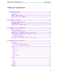
TABLE OF CONTENTS
PAGE
Introduction
3
Standard Equipment
3
Charging the Battery and Preparing the UNIT for Use
3-4
Operation of the DTT Meter with the Factory Defaults
4-5
Overload Capacity
5
Procedure for Manual Torque Drivers
6
Procedure for Power Screwdrivers
6
Instructions for using the Driver Adapter
7-8
Parts and Accessories
8
Calibration
9
Service and Warranty
9
System Overview
10
DTT Meter Specifications Sheet
11
Torque Conversion Factors
12
NOTE!
The Programming and Calibration Manual contains the password to enter the
calibration menu. To prevent tampering or unauthorized access, separate the Operation
Manual from the unit and store it away from the meter. You may also change the default
password to prevent unauthorized entry into the calibration program. However, if you change
the password and lose it, or forget it, the meter must be returned to ASG to restore the
default password.
2
1)
INTRODUCTION
Thank you for purchasing an ASG DTT Torque Meter. We know you have a choice and
all of us here at ASG are pleased that you chose our meter. Please feel free to contact
us with any comments regarding this, or any other ASG product at the phone number,
fax number or e-mail address provided on the first and last page of this guide. Normal
working hours are from 8:00 AM to 5:00 PM Eastern Standard Time.
This User Guide is designed to explain the physical operation of your new meter.
Please read this thoroughly to familiarize your self with this operating procedure. Refer
to the ASG DTT PROGRAMING and CALIBRATION MANUAL for instructions on the
various features available in the ASG DTT Meter.
You can determine the features you wish to have available to the operator by
programming them into the meter and saving the set up. Those features will then be
part of the systems default setting and are activated each time the meter is turned on.
Each ASG-DTT meter is designed to give convenient and accurate torque
measurement as a portable unit.
The unit can be used with most torque setting devices including Hand torque
screwdrivers, Electric torque screwdrivers, and pneumatic screwdrivers.
Do not use this unit with impact tools. The purpose of the unit is for setting the
torque level of fastening tools for consistent fastening torque. The proper fastening
torque will prevent breaking fasteners or loosening of the fastener after installation.
2)
STANDARD EQUIPMENT
All DTT meters are supplied with the following standard items:
Plastic carrying case
RS-232 Communication cable
ASG Memloader download software
110 VAC battery charger
Certificate of Calibration
Operation Manual
Programming and Calibration Manual
66620 .25 to 2 lbf.in driver adapter standard with DTT-5 and DTT-10
66612 driver adapter with 66614 yellow spring 1.3 to 5 lbf.in standard with DTT-5,
DTT-10, DTT-100, DTT-200
66616 black spring for use with 66612 allows 4.3 to 26 lbf.in standard with DTT-10,
DTT-100, and DTT-200
66618 25 to 90 lbf.in driver adapter standard with DTT-100, DTT-200
3)
CHARGING THE BATTTERY AND PREPARING THE UNIT FOR USE
CAUTION
If the battery overheats during charging a thermal fuse will open. The unit
will not operate until the fuse resets. Allow the DTT meter to sit for up to 30
minutes with the charger disconnected then turn the unit back on.
Before using the DTT-100 make sure the batteries have been charged for at least 4
hrs. If the batteries are low, the LCD may not function. A “Low battery” warning may
also be displayed on the LCD when the unit is turned on. The words “battery empty”
will be displayed briefly before the unit automatically shuts down.
3
If the battery is dead and you wish to use the meter, it is acceptable to occasionally
use the unit with the battery charger plugged in while the battery is charging. If the
battery dies during use, the on/off switch will need to be cycled to use the unit after
the charger is connected. Allow the battery to fully charge then detach the charger.
The battery will be fully charged after up to 3 hrs of charging.
Only use the charger supplied with the DTT meter. The supplied charger is a battery
charger only. It is not to be used as an AC adapter to power the DTT meter in
place of using the batteries in normal operation.
To use, place the unit on a smooth, flat, level surface. Clamp the unit using the
optional calibration / mounting bracket if higher torques are to be used.
To attach the bracket, remove the screws holding the 4 rubber feet found on each
corner of the unit. The back plate is held in place by 2 more mounting screws. DO
NOT REMOVE THESE SCREWS, OR REMOVE THE BACK PLATE OR THE
WARRANRY IS VOIDED. The bracket may be mounted with the clamping knobs at
the top of the unit, or at the bottom of the unit. Replace the screws and rubber feet to
retain the bracket. Do not over tighten and distort the rubber feet
Select the proper torque units. The unit will default to lbf.in when you turn it on. You
can use the “UNIT” button to scroll through the available units until you find the one
you want.
If the unit is not at 0 press the “RESET / ESC” button. The unit will default to the PEAK
setting when turned on. Use the “MODE” button to change to the TRACK or FIRST
PEAK setting if desired.
4)
OPERATION OF THE DTT METER WITH THE FACTORY DEFAULTS
The meter comes from the factory ready for normal operations. The POWER SWITCH,
BATTERY CHARGER CONNECTOR, and RS-232 SOCKET are on the left side of the
meter. The SERIAL NUMBER is on the back of the meter.
There are 4 buttons located on the front of the meter near the bottom. The buttons
perform various tasks depending on whether the meter is set to do normal operations
or if you are programming the meter.
Following are the functions of the buttons when in normal operating mode.
Button # 1
MENU
RESET/ESCAPE
Button # 2
DOWN
MODE
Button # 3
UP
UNIT
Button # 4
MEMORY
ENTER
Button #1: RESET
In normal operation, pressing the RESET button resets the torque readings to zero in
either the PEAK or FIRST PEAK mode.
4
Note! In TRACK MODE pressing the RESET button will take you into the MAIN MENU.
Press the button again to ESCAPE back to the previous screen and press the MODE
button to return to PEAK or FIRST PEAK Mode.
Button #2: MODE
In normal operation, the MODE button is used to change the MODE setting of the DTT
meter. Each time the button is pressed the mode will change from TRACK mode to
PEAK, or from PEAK to FIRST PEAK, or from FIRST PEAK to TRACK.
Button #3: UNIT
In normal operation, this button changes the torque units of the meter. Pressing the
button will scroll through the 9 choices. Kgf-cm, gf-cm, Kgf-m, mN-m, cN-m, N-m,
ozf-in, lbf-in, lbf-ft, in this order. Do not attempt to back up by pressing the DOWN
button; you will only change the mode.
Button #4: MEM (Memory)
In normal operation, pressing the MEM button enters the torque reading into the DTT
memory.
During normal operation, the LCD display will show: The Measurement Mode in the
upper left-hand corner of the LCD. The Measurement Units in the upper right hand
corner of the LCD. The Torque Reading in the center of the LCD, The Current Time in
the lower left hand corner of the LCD and the circle (or CW / CCW arrow) showing the
direction the torque was applied. This will be referred to as the operating display.
5)
OVERLOAD CAPACITY
CAUTION!
Do not deliberately exceed the capacity of the unit. The maximum capacity of
the DTT meter can be found on the spacer ring surrounding the transducer where it
says "MAX CAPACITY XXXlbf.in
The overload capacity of a DTT meter is 200% of its maximum load capacity. If the
meter is taken over capacity; a warning tone will sound, the word “OVERLOAD” will
flash on the LCD and the unit will LOCK until the RESET button is pressed.
Immediately stop applying torque when the overload warnings are observed.
A unit subjected to overload, or subjected to harsh conditions such as use with an
impact tool will not be covered under warranty.
5
6)
PROCEDURE FOR MANUAL TORQUE DRIVERS
Attach a proper adapter to connect the driver to the 3/8” female square. Use of one of
the driver adapters supplied with the meter is NOT RECCOMENDED
Select FIRST PEAK mode using the “MODE” button. Press the “RESET / ESC”
button if the display is not at 0.
Turn the driver or wrench clockwise or counterclockwise until the “break” point is
reached. In FIRST PEAK no other reading can then be displayed until the reset button
is pressed.
The LCD display will show the torque that the driver or wrench is set at. Note the
reading or write It down. To enter it into the DTT memory press the “MEM / ENTER”
button. If you are testing several tools note the memory numbers of the readings for
the various tools. This number is in the bottom right hand corner of the LCD. The unit
can save up to 200 readings. After that no further readings can be entered until the
memory is cleared. See the operating manual for instructions on downloading and
clearing the readings in the memory.
If the torque is not correct, adjust the tool. Repeat the test. When the reading is
proper perform the test several times to be sure the readings are stable. The proper
reading may be an average of several readings.
7)
PROCEDURE FOR POWER SCREWDRIVERS
Put the driver adapter into the unit’s female 3/8” square socket. This is also called a
joint simulator. It allows the power tool to reach its working speed before tightening
up and causing the clutch to operate. Select the adaptor that has a higher
reading that the capacity of the tool being tested.
Run the tool in reverse to make sure the adapter is unwound. Take care not to
disassemble the driver adapter.
Make sure the unit is in PEAK mode. If it is not use the “MODE” button to select Peak
mode. Press the “RESET / ESC” button to be sure the display is at 0Run the tool
forward until it shuts off. The reading on the display will be the torque setting of the
tool’s clutch. Note the reading or write it down. To enter it into the units memory
press the “MEM / ENTER” button. If you are testing several tools note the memory
numbers of the readings for the various tools. This number is in the bottom right hand
corner of the LCD. The unit can save up to 200 readings. After that no further readings
can be entered until the memory is cleared. See the operating manual for instructions
on downloading and clearing the readings in the memory.
If the torque is not correct, adjust the clutch. Repeat the test. When the reading is
proper perform the test several times to be sure the readings are stable. The proper
reading may be an average of several readings.
6
8)
INSTRUCTIONS FOR USING THE DRIVER ADAPTER
Use an adapter that has a higher capacity than the tool you are using. Before
using the adapter, make sure the thread is unwound but engaged. Turn the shaft by
hand to make sure the thread is turning smoothly and the bearing is also turning
smoothly.
When using hand torque drivers a hex to square adapter rather than the
power tool adaptor
Refer to the pictures below to identify the various driver adapters and springs to
determine the proper set up to obtain the correct match for measuring torque
A note about the various springs used in the driver adapters for the DTT meters. The spring
for #66620 adapter is black but is smaller than any of the other springs. It is also shorter than
any of the other springs.
There have been 2 versions of the #66618 adapter supplied with the DTT-100. The spring
supplied with the current version is black and larger than any of the other springs.
Spring #66614 which is gold, or yellow, and spring #66616 which is black, have similar inside
diameters. Spring #66616 will be a larger wire diameter but may be shorter than the gold
(yellow) spring.
7
It is normal for the adapter to occasionally become unscrewed or disassembled during
use. Refer to the drawing below for proper assembly rather then relying on the
creativity of individuals. All ASG DTT driver adapters using springs, regardless of
torque range or size, have similar parts and will be assembled in the same order.
It may be possible to extend the life of the bearing set (#2) After a groove appears on
the two races they may be turned over to provide a fresh surface. If the balls or rollers
in the center section are damaged replace the whole assembly
Lubricate #1, #2 & #5 as needed
with molybdenum grease
Inspect the thread on #1 and #5
periodically. Make sure the thread
turns smoothly. After 2500 cycles
check for wear and replace if
needed.
Clean, inspect and lubricate #2
After 2500 cycles. Replace if
bearing is not turning smoothly.
Replace #4 after 100,000 cycles
Never leave the spring compressed after use
If the adapter is disassembled refer to the diagram for re-assembly.
9)
PARTS AND ACCESSORIES
66620 Replacement Driver Adapter 4mm drive, .25 to 2 lbf.in, 3/8” square base
66612 Replacement Driver Adapter ¼” hex drive 3/8” square base, includes
66614 spring and 66616 spring
66614 Replacement Gold (Yellow) Spring for 66612, 1.3 to 5 lbf.in
66616 Replacement Black Spring for 66612, 4.3 to 26 lbf.in
66618 Replacement Driver Adapter ¼” hex drive 25 to 90 lbf.in. (New "one piece" unit
replaces earlier "2 piece" unit)
66610 Replacement 110 VAC battery charger
66622 Replacement RS-232 communication cable
66624 Optional Calibration/ Mounting bracket
66628 Optional Aluminum Briefcase
66630 Optional 220-240 VAC battery charger
8
10)
CALIBRATION
ASG recommends that qualified personnel calibrate the DTT meter once a year.
The Meter may be easily checked to insure it is in calibration. Calibration, or
calibration check must be performed only with the unit operating on battery power.
Do not perform a calibration, or calibration check while the battery charger is
attached.
Attach the optional calibration- mounting bracket and clamp the meter to a level
surface. Attach the proper calibration wheel, or arm and hang calibration weights.
The accuracy of the DTT meter is better than + - .2% of full scale. This means that on
a DTT-100 the reading should be with in +- .2 lbf.in of the actual torque.
Example: Using a 10” arm and 1 lb. the meter should read 10 lbf.in. A reading over
9.8 lbf.in or under 10.2 lbf.in would be within calibration. If the reading is over 10.2
lbf.in or under 9.8 lbf.in the meter would need re-calibration. The unit may be
returned to ASG for calibration. Simply contact ASG, or your local distributor, for a
repair number before returning the unit to ASG. ASG may refuse items returned
without a repair or return number.
11)
SERVICE & WARRANTY
ASG warrants to the original purchaser buying the ASG DTT meter with the intention
of use rather than resale, for a period of 1 year.
ASG will replace those items found to be defective or otherwise fail to conform or at
ASG’s option repay the price paid for the item. The Buyer’s remedies with respect to
any item found to be defective or otherwise not conforming shall be limited
EXCLUSIVELY to the right of replacement or repayment. In no event shall ASG be
liable for any incidental special or consequential damages or for damages n the nature
of penalties.
Disclaimer: Seller makes no other warranty whatever, expressed or implied, and all
implied warranties of merchantability and fitness for a particular purpose are
disclaimed and excluded from this transaction and shall not apply to the goods sold
hereunder.
The ASG DTT meter is an electronic instrument and should be treated with the same
care given any sensitive electronic instrument. Avoid dropping the unit or dropping
items on the unit. Avoid high shock loads to the transducer. Use the proper driver
adapter when using clutch type power tools.
9
SYSTEM OVERVIEW
ASG DIGITAL TORQUE TESTER
MODEL:
DTT-5 / DTT-10 / DTT-100
Physical:
Size:
7-1/8” x 4-3/8” x 2” (110x181x50 mm.)
Weight:
Electronics
Display:
4 LB (1.8 kgs.)
Graphics LCD display size 128 x 64 dots
Battery:
12 Hours (NiMH 7.2V rechargeable)
Battery charger:
110-120 VAC 60 Hz 12W input
12 VDC 500mA output
Optional 220-240 VAC input available
ADC:
24 bits
CPU:
8 bits
Communication:
RS232C
Key button:
4 Buttons
Unit of measure:
9 User Selectable Torque Units
Mode of Measure:
3 Modes
Display Digits:
6 Digits maximum
Special Function:
Auto Reset, Auto Memory, Auto Zero, Go – No Go,
Real Time Clock
Memory:
200 readings with alarm when full
10
D T T
M E T E R
MEASUREMENT RANGE
S P E C I F I C A T I O N S
S H E E T
MODEL
kgf-cm
lbf.in
N-m
DTT-5
.025 - 5.00
.025 – 5.00
.005 – .500
DTT-10
.050 – 10.00
.050 – 10.00
.005 – 1.000
DTT-100
.500- 100.00
.500 – 100.00
.500 – 11.300
MEASUREMENT UNIT
Kgf.cm , gf.cm , kgf.m , mN.m , cN.m , N.m, ozf.in , lbf.in , lbf.ft
ACCURACY
Better than +- 0.2 % of full scale
MEASUREMENT MODE
TRACK , PEAK , FIRST PEAK
DIMENSIONS in. (mm)
4.33” X 7.12” X 1.96” (110 X 181 X 50 mm.)
WEIGHT lb. (Kg.)
4 lb. (1.8 Kg)
BATTERY CHARGER
AC.120 VAC INPUT, DC 12 V. 500 mA OUTPUT
OPTIONAL 220-240 VAC unit AVAILABLE
RECHARGEABLE BATTERY
7.2 V. NIMH CELL 1200 mA. x 6
RECHAGING TIME
UP TO 4 HOURS
CONTINUOUS USE AT FULL
CHARGE
12 HOURS
OUTPUT
RS232C (serial port)
OVER LOAD
200 % of full scale
11
TORQUE CONVERSION FACTORS
ozf.in = inch ounces
lbf.in = inch pounds
lbf.ft = foot pounds
Units to be
Converted
gmf.cm = gram centimeters
mNm = mili Newton meters
kgf.cm = kilogram centimeters cN.m = centi Newton meters
kgf.m = kilogram meters
N.m = Newton Meters
Imperial
Metric
ozf.in
lbf.in
lbf.ft
International
gf.cm
kgf.cm
kgf.m
mN.m
cN.m
N.m
1 ozf.in
=
1.0
0.0625
0.005
72.0
0.072
0.0007
7.062
0.706
0.007
1 lbf.in
=
16.0
1.0
0.083
1152.1
1.152
0.0115
113.0
11.3
0.113
1 lbf.ft
=
192.0
12.0
1.0
13826.0
13.83
0.138
1356.0
135.6
1.356
1 gf.cm
=
0.014
0.0009
0.00007
1.0
0.001
0.0001
0.098
0.01
0.0001
1 kgf.cm =
13.890
0.868
0.072
1000.0
1.0
0.01
98.07
9.807
0.098
1 kgf.m
1389.0
86.8
7.232
100000.0
100.00
1.0
9807.0
980.7
9.807
1 mN.m =
0.142
0.009
0.0007
10.2
0.01
0.0001
1.0
0.1
0.001
1 cN.m
=
1.146
0.088
0.007
102.0
0.102
0.001
10.0
1.0
0.01
1 N.m
=
141.6
8.851
0.738
10197.0
10.20
0.102
1000.0
100.0
1.0
=
Multiply the units to be converted by the number under the units you want.
Example 20 kgf.cm = ? lbf.in
1 kgf.cm = .868 lbf.in, therefore 20 kgf.cm = 20 x .868 or 17.36 lbf.in
12


