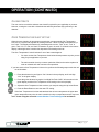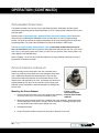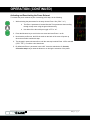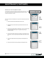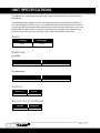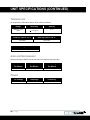
1
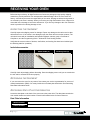
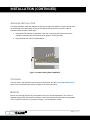
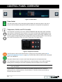
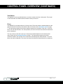
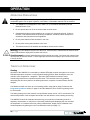
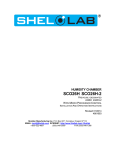
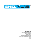
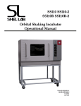
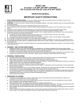
Sheldon High-Performance Oven 230 Voltage Installation and Operation Manual SMO5HP-2 Previously designated as HF4-2 Sheldon Manufacturing Oven High Performance 230 Voltage Installation and Operation Manual Part Number (Manual): 4861706 Revision: July 28, 2014 Purge Valve The SMO5HP-2 can be built with a purge valve located on the back of the unit. The valve can be connected to a cylinder of nitrogen (N2) or other neutral gas to purge the oven chamber. This option must be ordered prior to the construction of the oven. These units are forced air ovens for professional, industrial, or educational use where the preparation or testing of materials is done at approximately atmospheric pressure and no flammable, volatile, or combustible materials are being heated. These units are compliant with the following standards: CAN/CSA C22.2 No. 61010-1:2012 CAN/CSA C22.2 No. 61010-2-010 + R:2009 UL 61010A-2-010:2002 UL 61010-1:2012 EN 61010-1:2010 EN 61010-2-010:2003 2|Page TABLE OF CONTENTS General Safety Considerations ................................................................................................................. 4 Engineering Improvements ....................................................................................................................... 5 Contacting Assistance ............................................................................................................................... 5 RECEIVING YOUR OVEN ............................................................................................................................ 6 Inspecting the Shipment ............................................................................................................................ 6 Returning the Shipment ............................................................................................................................ 6 Recording Data Plate Information ............................................................................................................. 6 Orientation ................................................................................................................................................. 7 GRAPHIC SYMBOLS ................................................................................................................................... 8 INSTALLATION ............................................................................................................................................ 9 Ambient Conditions ................................................................................................................................... 9 Location ..................................................................................................................................................... 9 Lifting and Handling .................................................................................................................................. 9 Leveling ................................................................................................................................................... 10 Power Source .......................................................................................................................................... 10 Shelving Installation ................................................................................................................................ 11 Cleaning .................................................................................................................................................. 11 Burn In ..................................................................................................................................................... 11 CONTROL PANEL OVERVIEW ................................................................................................................. 12 OPERATION ............................................................................................................................................... 14 Operating Precautions ............................................................................................................................ 14 Theory of Operations .............................................................................................................................. 14 Setting up the Oven ................................................................................................................................ 15 Set the Over Temperature Limit .............................................................................................................. 16 Set the Temperature Controller Set Point ............................................................................................... 16 First Use Burn In ..................................................................................................................................... 17 Calibrating the Unit .................................................................................................................................. 17 Closed Vents ........................................................................................................................................... 19 Over Temperature Limit Active ............................................................................................................... 19 Positive Venting of Exhaust .................................................................................................................... 20 USER MAINTENANCE ............................................................................................................................... 22 Cleaning .................................................................................................................................................. 22 Disinfecting .............................................................................................................................................. 22 Door Latch and Electronics ..................................................................................................................... 23 Door Gaskets .......................................................................................................................................... 23 Removing the Chamber Liner ................................................................................................................. 24 UNIT SPECIFICATIONS............................................................................................................................. 25 Weight ..................................................................................................................................................... 25 Dimensions .............................................................................................................................................. 25 Capacity .................................................................................................................................................. 25 Shelf Capacity by Weight ........................................................................................................................ 25 Temperature ............................................................................................................................................ 26 Airflow Performance ................................................................................................................................ 26 Power ...................................................................................................................................................... 26 REPLACEMENT PARTS............................................................................................................................ 27 Ordering Parts and Consumables ........................................................................................................... 27 3|Page INTRODUCTION Thank you for purchasing a Sheldon Manufacturing High Performance Oven. We know that in today’s competitive marketplace, customers have many choices when it comes to constant temperature equipment. We appreciate you choosing ours. Our continued reputation as a leading laboratory product manufacturer rests with your satisfaction. Sheldon Manufacturing, Inc. stands behind our products, and we will be here if you need us. These ovens are intended for professional, industrial, and educational applications requiring horizontal shelf space airflows. The ovens are not designed for use at hazardous or household locations. Before you use your oven read this entire manual carefully to understand how to install, operate, and maintain the oven in a safe manner. Keep this manual available for use by all oven operators. Ensure that all operators are given appropriate training before the oven begins service. GENERAL SAFETY CONSIDERATIONS Note: Failure to follow the guidelines and instructions in this manual may create a protection impairment by disabling or interfering with the unit’s safety features. This can result in injury or death. Your oven and its recommended accessories have been designed and tested to meet strict safety requirements. For continued safe operation of your oven, always follow basic safety precautions including: Follow all local or regional ordinances in your area regarding the use of this unit. If you have any questions about local regulations, please contact the appropriate agency. Use only approved accessories. Do not modify system components. Any alterations or modifications to your oven may be dangerous and will void your warranty. Always hardwire the unit’s power feed to an earth grounded electrical source that conforms to national and local electrical codes. If the unit is not grounded, parts such as, knobs and controls may conduct electricity and cause serious injury. Avoid damaging the power feed. Do not bend it excessively, step on it, place heavy objects on it. A damaged power feed can easily become a shock or fire hazard. Never use a power feed after it has been damaged. Do not position the equipment in such a manner as to make it difficult to disconnect or uncouple the power feed. Do not attempt to move the unit while in operation or before the unit has cooled. 4|Page INTRODUCTION (CONTINUED) ENGINEERING IMPROVEMENTS Sheldon Manufacturing continually improves all of its products. As a result, engineering changes and improvements are made from time to time. Therefore, some changes, modifications, and improvements may not be covered in this manual. If your unit’s operating characteristics or appearance differs from those described in this manual, please contact your Shel Lab dealer or customer service representative for assistance. CONTACTING ASSISTANCE If you are unable to resolve a technical issue with the oven, please contact Sheldon Technical Support. Phone hours for Sheldon Technical Support are 6am – 4:30pm Pacific Coast Time (west coast of the United States, UTC -8). Please have the following information ready when calling or emailing Technical Support: the model number and the serial number. These will be found on the unit’s data plate, which is located on the back of the unit at the top right, next to the power supply as mandated by regulatory requirement. EMAIL: [email protected] PHONE: 1-800-322-4897 extension 2, or (503) 640-3000 FAX: (503) 640-1366 5|Page RECEIVING YOUR OVEN Before leaving our factory, all High Performance Ovens are packaged in high-quality shipping materials to provide protection from transportation-related damage. When an oven leaves our factory, safe delivery becomes the responsibility of the carrier. Damage sustained during transit is not covered by the oven’s warranty. When you receive your High Performance Oven, inspect it for concealed loss or damage to its interior and exterior. If you find any damage to the oven follow the carrier’s procedure for claiming damage or loss. INSPECTING THE SHIPMENT Carefully inspect the shipping carton for damage. Report any damage to the carrier service that delivered the oven. If the carton is not damaged, open the carton and remove the contents. The unit should come with an Installation and Operation Manual, warranty card, a Certificate of Compliance, and the Programming Guide – Watlow EZ-Zone Heating Profiles. Verify that the correct number of shelves, shelf slides, and leveling feet have been included (see the following table for quantities). Included accessories Shelves (2) Shelf Slides (4) Leveling Feet (4) Carefully check all packaging before discarding. Save the shipping carton until you are certain that the unit and its accessories function properly. RETURNING THE SHIPMENT If you must return the oven for any reason, first contact your service representative for a return of material authorization (RMA). You must provide the unit’s data plate information. See Recording Data Plate Information below. RECORDING DATA PLATE INFORMATION Locate the data plate on the back of the oven next to the power inlet. The data plate contains the oven model number and serial number. Enter this information below for future reference. Date Plate Information Model Number Serial Number 6|Page RECEIVING (CONTINUED) ORIENTATION Permanent Connect Wire Braid 14 gauge, 6 inches (15 cm) Back Panel Fuse Holders External Power Outlet Nitrogen Gas Inlet (Optional Order Item) Note: The external power outlet type varies by country and voltage. Intake Vent Control Panel Exhaust Vent Exhaust Vent Valve Control Power Switch Intake Vent Valve Control Chamber Ceiling Liner Door Latch Outer Door Gasket Left Wall Chamber Liner Right Wall Chamber Liner Chamber Gasket Door Latch Figure 1: Orientation Photo 7|Page GRAPHIC SYMBOLS The oven is provided with multiple graphic symbols on its external and internal surfaces. The symbols identify hazards and the functions of the adjustable components, as well as important notes found in the user manual. Symbol Definition Indicates that you should consult your service manual for further instructions. Indique que l'opérateur doit consulter le manuel d'utilisation pour y trouver les instructions complémentaires. Indicates Adjustable Temperature Indique température réglable Indicates AC Power Repère le courant alternative Indicates I/ON and O/OFF I repère de la position MARCHE de l'interrupteur d'alimentation O repère de la position ARRÊT de l'interrupteur d'alimentation Indicates protective earth ground Repère terre électrique Indicates UP and DOWN respectively Touches de déplacements respectifs vers le HAUT et le BA Indicates a Potential Shock Hazard Signale danger électrique WEEE Directive compliant logo Indicates the unit should be recycled (Not disposed of in land-fill) Indique l’appareil doit être recyclé (Ne pas jeter dans une décharge) Indicates: Caution hot surface Indique: Avertissement symbole de surface chaude 8|Page INSTALLATION Installation of an SMO5HP-2 requires permanent connect wiring (commonly known as hardwiring), and must be performed by a qualified electrical technician. All other installation steps can be performed by the end user. AMBIENT CONDITIONS This oven is intended for use indoors, at room temperatures between 15C and 40C (59F and 104F), at no greater than 80% Relative Humidity (at 25C / 77F). Allow a minimum of 12 inches (30cm) between the oven and any walls or partitions, and 24 inches (60cm) of vertical headspace clearance above the top of the oven for unobstructed airflow and cooling. If the oven’s exhaust will be vented from the workspace through a duct or other channeling, 12 inches (30cm) of vertical clearance will suffice. Make sure the intake and exhaust vent remain unobstructed. Do not place objects on top of oven, aside from the power exhaust accessory described in the manual. Operating the unit outside these conditions may adversely affect the oven’s temperature range, uniformity, and stability. For conditions outside of those listed above, please contact your distributor or Shel Lab Sales to explore other ovens suited to your production of laboratory environment. LOCATION When selecting a location to install the oven, consider all conditions that can affect temperature performance. For example: Ovens, autoclaves, and any device that produces significant radiant heat Heating and cooling ducts, or other sources of fast moving air currents High-traffic areas Direct sunlight LIFTING AND HANDLING The oven is heavy. Use appropriate lifting devices that are sufficiently rated for these loads. Follow these guidelines when lifting the oven: Lift the oven only from its bottom surface. Doors, handles, and knobs are not adequate for lifting or stabilization. Restrain the oven completely while lifting or transporting so it cannot tip. Remove all moving parts, such as shelves and trays, and secure the door in the closed position during transfers to prevent shifting and damage. 9|Page INSTALLATION (CONTINUED) LEVELING The oven must be level and stable for safe operation. Each high performance oven ships with four leveling feet. Insert one leveling foot into each of the four holes in the bottom corners of the oven. Stand the oven upright. Then, adjust the foot at each corner until the oven stands level and solid without rocking. To raise a foot, turn it in a counterclockwise direction; to lower a foot, turn it in a clockwise direction. Note: To prevent damage when moving the oven, turn each of the four leveling feet completely clockwise. POWER SOURCE The oven is intended for 230 volt, 50/60 Hz applications at 12 Amps. Check the oven’s data plate to verify voltage and ampere requirements before wiring to a power source. The oven’s power feed must be wired into an earth grounded source. The oven comes provided with an integral 6 inch (15 cm) wire braid of two 14 gauge high-temperature (300°C) hot wires and a 14 gauge earth ground. See the Orientation figure on page 7. The power source for the oven must conform to all national and local electrical codes Supplied voltage must not vary more than 10% from the data plate rating. Damage to the oven may result if supplied voltage varies more than 10%. Before energizing the oven it must be earth grounded using the protective conductor terminal (green with yellow stripe wire. Do not remove the protective conductor (earth connection). Removing the protective conductor will negate the oven’s protections against potentially dangerous electric shocks and create a possible fire hazard. A separate circuit is recommended to prevent possible loss of product due to overloading or failure of other equipment on the same circuit. A switch or circuit-breaker must be used in the building installation. The required circuit-breaker is 20 Amps. The wires for power source connection should be in accordance with the following for all units: Green/Yellow – Earth; Black – Hot; Red – Hot. The power feed Disconnect must be in close proximity to the equipment and within easy reach of the operator. The power feed Disconnect must be marked as the disconnecting device for the equipment. 10 | P a g e INSTALLATION (CONTINUED) SHELVING INSTALLATION The horizontal airflow within the chamber moves from the right-wall chamber duct to the large holes on the left side. Place the shelves so they do not obstruct the duct holes on the left in order to maximize airflow across the shelf space. 1. Install shelf slide hangers on opposites of the oven by inserting the slider’s tabs into the chamber’s mounting slots, then pushing down gently to secure the slider. 2. Hang the shelf from the two installed sliders. Figure 2: Installed Sliding Shelf, SMO5HP-2 CLEANING The oven interior was cleaned at the factory but not sterilized. See the Cleaning and Disinfection topics in the User Maintenance section on page 22 for more information. BURN IN Run the oven through the Burn In process before using it for normal applications. This is done to eliminate smoking from the protective coatings on the oven’s heating elements when running above 150°C. Please see the Burn-In procedure on page 17 of the Operation section. 11 | P a g e CONTROL PANEL OVERVIEW Figure 3: Control Panel Power Switch The main power switch on the control panel (green lighted I/O) controls all power to the oven. It must be in the illuminated I (ON) position before any systems or components are operational. Temperature, Profile, and OTL Controller The temperature controller for the oven is labeled TEMPERATURE AND HIGH LIMIT CONTROL and consists of a Watlow EZ-Zone Controller. The control is provided with a digital display and up and down arrow keys for adjusting the oven’s temperature set point, performing a calibration, and choosing pages and adjusting parameter settings while setting up heating profiles. The arrow keys also control the operations of the oven’s Over Temperature Limit system (OTL). Figure 4: Temperature Controller The EZ1 button is used to quick launch Profile 1 or abort any running heating profile (see the Programmed Operations section on page 20). The EZ2 button does not have function associated with it in the SMO5HP-2. The green advance button is used to scroll forward through menus and parameters lists. The reset button is used to scroll the display back to a previous page or menu while programing heating profiles. Pressing the reset button repeatedly returns the display to the home page. Note: On some older Watlow Controllers the Reset button may be labeled with an infinite ∞ symbol rather than RESET. A small flashing “2” toward the center bottom of the display indicates when the controller is powering the oven’s heating elements. A small flashing “1” indicates internal communications functions within the controller. 12 | P a g e CONTROL PANEL OVERVIEW (CONTINUED) Vent Valves The SMO5HP-2 comes provided with two vent valve controls on its front control panel. These open or close the intake and exhaust valves located on the top of the unit. Fuses The SMO5HP-2 is provided with two (2) 20 amp fuses. These are located in holders adjacent to the power feed braid on the back power panel of the unit. Please see the Orientation photo on page 7. The fuses protect against overcurrent conditions related to the operation of the oven. If one fuse blows, the oven will shut down. For safe operation, the cause of a blown fuse should be determined prior to replacing it. The oven is also provide with a pair (2) of 2 amp fuses installed adjacent to the external power outlet. Please see the Orientation photo on page 7. The fuses protect against overcurrent conditions related to the operation of the outlet and an attached power exhaust blower. If one fuse blows, the outlet will depower. The cause of a blown fuse should be determined prior to replacing it. 13 | P a g e OPERATION OPERATING PRECAUTIONS Warning: The SMO5HP-2 is not an explosion proof unit! The oven is not designed to safely contain combustible gasses. Do not place explosive, combustible, or flammable materials into the chamber. 1. The SMO5HP-2 not designed for use in Class I, II, or III locations as defined by the US National Electric Code. 2. Do not operate the oven in an environment with noxious fumes. 3. Outgassed byproducts maybe hazardous to or noxious for operating personal. If either is the case, oven exhaust should be positively ventilated to a location outside workspace in accordance with national and local regulations. 4. Do not place sealed or filled containers in the oven. 5. Do not place mercury thermometers in the oven. 6. The bottom surface of the chamber should not be used as a work surface Warning: The vent dampers may be hot to the touch. These areas are marked with Hot Surface labels. Proper PPE should be employed to minimize risk to burn. Avertissement:Les clapets d'aération peuvent être chauds au toucher. Ces zones sont marqués avec des étiquettes de Surface chaude. Les EPI approprié devraient être employée pour réduire au minimum le risque de brûler. THEORY OF OPERATIONS Heating Operation of the SMO5HP-2 is controlled by a Watlow EZ digital controller through the use of userselected temperature set points or user-programed heating profiles. When heating the oven, the controller users Proportional – Integrative – Derivative (PID) feedback functions to avoid overshooting temperature set points and profile levels. The controller does so by gradually decreasing the amount of power to the heating elements in response to measurements and PID analysis. The Watlow controller can store up to four heating profiles, each with ten steps. Please see the Programed Operations section on page 20, and the Watlow EZ-Zone Profile Programing Guide for more details. The heating rates given in this manual’s unit specification section are for a 25°C environment. The ambient temperature of the workspace around the oven will affect the oven’s heating and cooling The SMO5HP-2 should be calibrated as required by your production or laboratory protocol, or regulatory requirements, to verify that it is accurately measuring and displaying the oven chamber air temperature. If a measurement error (offset) is detected the, display can be calibrated to the actual temperature by placing the oven in its calibration mode (see page 17.) 14 | P a g e OPERATION (CONTINUED) Airflow and Applications During normal operations an internal blower fan motor pulls air in through the intake vent. The captured air is blown across heating elements and then forced down through a duct on the right side of the oven chamber. Upon leaving the duct, the heated air blows horizontally across the shelf space, helping to create temperature uniformity and enhance drying. After crossing the shelves, the air enters a duct on the left side of the chamber, and is then pulled back into the heater space above the oven chamber. During each minute of operation some air exits through the open exhaust vent on the top right of the unit. Lost air is replaced through the intake vent. The rate of atmosphere exchange on several variable factors. These include: ambient conditions, position of the vent valves, the volume of material in the oven chamber, and if a power exhaust unit is connected to the exhaust vent. Over Temperature Limit The Watlow controller contains a backup temperature control system with independent circuitry connected to a redundant temperature sensor probe inside the oven chamber. To set up this system for use, the user enters an over temperature limit into the Watlow controller — typically 5°C above the application or process temperature set point. In the event the oven temperature exceeds the over temperature limit, the backup system will depower the heating element. This provides redundant heating control the event of a failure of the primary circuitry or the main temperature sensor probe. Power Exhaust Outlet SMO5HP-2 Ovens come provided with a power outlet that can be used to power an exhaust blower unit attached to the oven’s exhaust vent. The power outlet and attached fan can be activated by the Watlow controller as part of a heating profile. The primary application of the power exhaust fan is to channel or positively vent exhaust out of the workspace around the oven. SETTING UP THE OVEN 1. After the oven has been installed in the location where it will be used, open the oven’s intake and the exhaust vents. 2. Push the Power Switch to the ON position. The Temperature Display will illuminate. 3. Set up the oven for use by carrying out the following procedures found in this manual’s Operation section: Set the Over Temperature Limit (pg. 16) Home Page Set the Temperature Controller Set Point (pg. 16) Temp in Red First Use Burn-In (pg.17) Set Point in Green Calibrating the Unit (pg. 17) 15 | P a g e OPERATION (CONTINUED) SET THE OVER TEMPERATURE LIMIT This procedure sets the Over Temperature Limit backup system. This is typically 5°C above the set point temperature you will be using during your application or process, or 5°C above the hottest temperature of your heating profile. Note: If this is the first use of the oven, set the Over Temperature Limit to 325°C to prepare for the Burn In procedure. This helps ensures the OTL system will not interfere with the Burn In procedure. 1. Press the green Advance button until “Lh.S1” (Limit High Set Point) shows in the greencolored mid-level display. 2. Use the Up and Down arrows to enter a temperature limit in the red top display. 3. After entering the temperature limit, press the Advance button. The red display will show “SAFE”, indicating that the temperature limit has been set. 4. Press the Reset button to scroll the display back to the home page. SET THE TEMPERATURE CONTROLLER SET POINT This procedure sets a new temperature set point for the oven. Note: Set the temperature to the highest operating temperature the oven will be run at. This prepares the oven for the First Use Burn-Ion procedure (see page 17). 1. On the home page, use the Up and Down Arrow keys to adjust the set point in the green display to your baking application or process temperature set point. a. Holding down an arrow key will cause the temperature to advance in increments of ten (10) rather one (1). 2. Release the Arrow Button once you have reached your required set point. There may be a brief pause before the oven starts heating. a. A small flashing 2 in the Watlow display indicates when the temperature controller is calling for heat. Note: Please see the Quick Start – SHEL LAB Vacuum Oven Basic Video at http://www.shellab.com/store/virtual-tour-vac-oven.html for a demonstration of how to enter a temperature set point. The video applies to all ovens with the EZ-Zone Watlow controller. Note: The Reset Button on the controller of your Watlow is referred to as the Infinite Button in the video. End of procedure 16 | P a g e OPERATION (CONTINUED) FIRST USE BURN IN The steps below will help to eliminate smoking from the heating elements’ protective coatings when running above 150°C. Perform the burn-in at the highest temperature the oven will be used at. 1. Open the unit’s intake and exhaust vents. The oven’s exhaust should be positively vented outside of the oven’s workspace during the Burn-In. 2. If you have not already done so, set the Over Temperature Limit to 325°C, and the temperature set point the highest operating temperature the oven will be used at. 3. Run the oven for a minimum of one (1) hour, until smoke from the heating elements dissipates. CALIBRATING THE UNIT The oven should be calibrated at the temperature set point it will be run at. For heating profiles, the oven should be calibrated to the average temperature of the profile. 1. Close the exhaust vent if your application or process calls for the exhaust vent to be closed. Otherwise leave the vent open. The intake vent should always be open. 2. Place the temperature sensor of a certified reference device inside the oven, secured to the center of the center-most shelf. Note: Always use an independently certified temperature reference device that is regularly calibrated to 0.5°C accuracy or better to conduct temperature calibrations or verifications. . For best results, using a remote sensing reference device. 3. If you have not already done so, enter an Over Temperature Limit of 325°C to safeguard against the OTL System interfering with the calibration procedure. 4. If you have not already done so, enter the temperature set point you will use during your application or process. 5. Allow the chamber to heat to up the set point, and then stabilize with no change in temperature for at least a-half hour (30 minutes) prior to performing a temperature calibration. This is to ensure the best possible temperature uniformity and accuracy in the oven chamber. 6. Read the reference temperature device’s display. Compare its reading with the red temperature shown in the Watlow Controller’s Temperature Display. 7. If the reference device’s and the Watlow’s temperature readings are the same or fall within the range of your laboratory or manufacturing protocol, the oven is now calibrated. 8. If there is a temperature difference between reference device and the Watlow, and that difference falls outside your laboratory or manufacturing protocol’s acceptable range, adjust the Watlow to match the reference device’s reading by entering a temperature offset. See the next step. Procedure Continued on Next Page 17 | P a g e OPERATION (CONTINUED) Note: The accuracy of the calibration process is limited by the accuracy of your reference temperature device. The difference between the reference device and oven’s display is called an offset. Examples of offsets: Note: Reference Sensor Reading Watlow Temp. Display Offset Value 152°C 150°C 2 148°C 150°C -2 If the door was opened to check the reference device’s reading, allow the oven temperature ten minutes to stabilize before entering the offset. 9. Enter the temperature offset into the Watlow Controller. To do so, push and hold both the Up and Down Arrow Button simultaneously for three (3) seconds or until “Ai” appears in the Upper Display and “oPEr” appears in the Lower Display. 10. Push the green Advance Button repeatedly unit “i.CA” appears in the green middle display and a number value shows in the red top display. 11. Adjust the number value in the top display using the Up or Down Arrow Buttons to match the offset value. 12. Once the Offset Calibration Number is entered, push the Reset Button repeatedly to exit the calibration, save the set point, and return to the Home Page. 13. Wait for a half hour, then compare the reading of the reference device and the Watlow Controller. Enter an offset if the readings are still different and fall outside your laboratory protocol range. 14. If the temperature readings of the display and the reference device still do not fall close enough to be acceptable by your laboratory protocol after three calibration attempts, contact Sheldon Technical Support for assistance. Note: After calibrating the oven to your process or application temperature, set the Over Temperature Limit to 5°C above the process / application’s set point. If you will be running a programed heating profile, set the Over Temperature Limit to 5°C above the profile’s highest set point. End of Procedure 18 | P a g e OPERATION (CONTINUED) CLOSED VENTS The oven can be run with the exhaust vent closed if required for your application or process. However, running the oven with a closed exhaust will likely decrease drying efficiency in the chamber. OVER TEMPERATURE LIMIT ACTIVE When the oven chamber air temperature exceeds the user-programed Over Temperature Limit, the OTL system will depower the heating elements. This is normally accompanied by a loud “click.” The display will flash two (2) alternating alert screens. “FAiL” in red, “L.st1” in green. Then “Li.h1” in red, and “Attn” for attention in green. A small “4” will show in the bottom display, indicating that the controller has depowered the heating elements. The Over Temperature Limit will activate if one of two events happens. You have set the Over Temperature Limit below the temperature set point you are using for your application or process. The main controller circuitry or sensor probe has failed, and must be replaced in order to maintain safe and accurate oven operations. Alternating OTL Alert Screens If you have set the Over Temperature Limit too low, perform the following steps to take the unit out of shutdown: 1. Press the advance key until Ignore “i9nr” shows in the top display, and Limit High “Lih1” in the green display. 2. Press the green advance key again. Limit High Set Point “LhS1” will now show in the green display, and the Over Temperature Limit setting in the red top display. 3. Adjust the Over Temperature Limit to above your set point using the Up Arrow Button. 4. Push the Reset Button to save the new OTL setting. If the Over Temperature Limit has activated and the red oven temperature is higher than your green temperature set point, the main controller circuitry or temperature sensor may have failed. Cease using the oven and contact Sheldon Technical Support for assistance. 19 | P a g e OPERATION (CONTINUED) PROGRAMMED OPERATIONS The Watlow controller can hold four (4) ten-step heating profiles. Additionally, profiles may be combined by programing profile steps sequentially to run as a single profile of between two (2) and forty (40) steps. Please see the Programing Guide – Watlow EZ-Zone Controller Heating Profiles document, which comes included with the SMO5HP-2 oven, for instructions on how to program heating profiles. The guide is intended as simplified explanation for all major heating profile functions and programing steps. The guide is also available on the Shel Lab website in PDF format. The How to Program Ramp & Soak Profiles video at http://www.shellab.com/store/virtualtour-vac-oven.html shows how to program a three-step profile that will ramp the oven up to 150°C over a one (1) hour period; then hold (“soak”) at 150°C for four (4) hours; then end the profile. The video applies to the SMOHP family. Refer to Chapter 7 of the “EZ-Zone PM User’s Manual” for highly detailed instructions on how to program the EZ Watlow Controller. POSITIVE VENTING OF EXHAUST Exhaust ducting can be connected to the oven’s exhaust port to channel or positively vent exhaust out of the workspace around the oven. Additionally, Sheldon Manufacturing sells a 230 volt High Performance Power Exhaust that can be mounted directly on the exhaust vent, and powered by the oven. An exhaust duct should not extend straight up from the oven, but should include a steep bend sufficient to stop condensation within the ducting from sliding down into the oven. Mounting the Power Exhaust 1. Remove the screws on the cover of the exhaust vent assembly on the top of the oven, but leave the assembly in place. Figure 5: High Performance Power Exhaust (Part Number 9990741) 2. Mount the power exhaust blower on the exhaust vent cover assembly, aligning the blower and the assembly’s screw holes. The open side of the blower’s mounting body should go over the handle of the exhaust port’s sliding vent cover. 3. Reinstall the screws. 4. Plug in the power exhaust into the 230 volt outlet on the back of the oven. 20 | P a g e OPERATION (CONTINUED) Activating and Deactivating the Power Exhaust To activate the power exhaust as part of a heating profile step, do the following: 1. While selecting the parameters for the step, choose Event 1 On (“Ent1” “on”). a. The Event 1 parameter is located after the Time parameter when scrolling through a step menu using the green Advance Key. b. Use either of the Arrow Keys to toggle “oFF” to “on”. 2. Press the Advance key to scroll to the next event and save Event 1 as On. 3. Next time the profile runs, the 230 volt outlet on the back of the oven will power up when the controller reaches this step. 4. The plugged in power exhaust will run until the next step in which Event 1 Off is selected (“Ent1” “oFF”), or until the oven shuts down. 5. By default the Event 1 parameter is set to Off. It must be switched to On for each successive step that you want the blower to run during the execution of the profile 21 | P a g e USER MAINTENANCE Warning: Prior to any maintenance or service on this unit, disconnect the power feed from the power supply. Avertissement: Avant d'effectuer toute maintenance ou entretien de cet appareil, débrancher le cordon secteur de la source d'alimentation. If a hazardous material/substance has spilled in the oven, immediately initiate your site’s Hazardous Material Spill Containment protocol. Contact your local Site Safety Officer and follow instructions per the site policy and procedures. CLEANING Note: The oven’s chamber should be cleaned and disinfected prior to use. Perform the steps below to clean the oven: 6. Remove the shelves and sliders. 7. Clean the oven with a mild soap and water solution, including all corners. Do not use an abrasive cleaner that will damage stainless steel surfaces. 8. Rinse with distilled water and wipe dry with a soft cloth. Do not use deionized water. 9. Take care not to damage the temperature sensor probes when cleaning. These are located on the right side of the of the oven chamber back wall. Warning: Never clean the oven with alcohol or flammable cleaners. Avertissement: Ne jamais nettoyer l'appareil à l'alcool ou avec des nettoyants inflammables. Note: Do not use spray cleaners or disinfectants that might leak through openings and cracks and get on electrical components, or that contain solvents that will harm coatings. Do not use chlorine-based bleaches or abrasives; they will damage the chamber’s interior surfaces. DISINFECTING Disinfect the oven on a regular basis if required by your production or laboratory protocol, or if mold or fungus is an issue in your region. Perform the below steps to disinfect the oven: 1. Remove the shelves and sliders. 2. Disinfect the oven, including all corners and the access port, a using commercially available disinfectant that is non-corrosive, non-abrasive, and suitable for use on stainless steel surfaces. Contact your local Site Safety Officer for detailed information for the proper disinfectants compatible with your application or process. 3. Take special care when cleaning around sensing heads to prevent damage and around the door gasket so as not to impair the positive seal. 22 | P a g e MAINTENANCE (CONTINUED) DOOR LATCH AND ELECTRONICS Periodically, inspect the door latch, trim, catch, and gasket for signs of deterioration. Failure to maintain the integrity of the door system shortens the life span of the Oven. Electrical components do not require maintenance. If the oven fails to operate as specified, please contact your Shel Lab distributor or Sheldon Manufacturing Technical Support for assistance. DOOR GASKETS The Sheldon High Performance Oven is provided with a high temperature silicon door gasket. See the Parts Section on page 25 for ordering replacement gaskets. 23 | P a g e MAINTENANCE (CONTINUED) REMOVING THE CHAMBER LINER This procedure removes the ceiling liner and the side wall air ducts. The liner and ducts should be removed periodically and cleaned, and the surfaces beneath them cleaned. Note: Door removed in illustrations for clarity. Do not remove the door from the oven. 1, 2, 3) Remove Shelves, Nuts, and Door Gasket 1. Remove all shelves and shelf sliders from the oven. 2. Unscrew the nuts located at the top of the back wall of the oven chamber. 4) Ceiling Liner Removed 3. Remove the chamber gasket so that there is room to pull the ceiling liner out through the door space. The gasket may be fully or partially removed. 4. Remove the chamber ceiling liner by pulling it out through the oven door space. The liner may require some side-to-side motion to free up. 5) Right Air Duct Removed 5. Remove the right wall air duct by pulling it out through the door space. 6. Remove the left wall air duct by pulling it out through the door. 24 | P a g e 6) Left Air Duct Removed UNIT SPECIFICATIONS The SMO5HP-2 is a 230 voltage unit. Please refer to the oven’s data plate for individual electrical specifications. Technical data specified applies to ovens with standard equipment at an ambient temperature of 25°C and a voltage fluctuation of ±10%. The temperatures specified are determined in accordance to factory standard following DIN 12880 respecting the recommended wall clearances of 10% of the height, width, and depth of the inner chamber. All indications are average values, typical for units produced in the series. We reserve the right to alter technical specifications at all times. WEIGHT Shipping Net Weight 425 lbs 325 lbs DIMENSIONS By Inches Exterior W × D × H Interior W × D × H 35 x 30.5 x 37.5 20.5 x 20.7 x 20 By centimeters Exterior W × D × H Interior W × D × H 88.9 x 77.5 x 95.3 52 x 52.7 x 50.8 CAPACITY Cubic Feet Liters 4.9 139 SHELF CAPACITY BY WEIGHT Pounds Kilograms 50 lbs. per shelf 22.8 kg per shelf 25 | P a g e UNIT SPECIFICATIONS (CONTINUED) TEMPERATURE All temperature performance data for 25°C ambient conditions Range Uniformity Stability Ambient + 15 to 300C + 1.7C @ 110 0.1°C Heat Up Time to 110°C Heat Up Time to 180°C* 10 minutes 35 minutes Recovery to 110°C* 4 minutes after closing the door AIRFLOW PERFORMANCE Airflow performance data is for both the intake and exhaust vents fully open. Cubic Feet Per Minute Cubic Liters Per Minute Air Exchanges Per Minute 6.2 175.56 1.6 AC Voltage Amperage Frequency 230 12 50/60 Hz POWER 26 | P a g e REPLACEMENT PARTS Description Parts Number Adjustable Feet SMO5HP-2 2700512 Chamber Gasket Silicone (unit is per foot, requires 8 feet) 3750626 Door Gasket SMO5HP-2 Silicone (unit is per foot, requires 11 feet) 3450587 Fuse 20 Amp 3300538 Shelf Slide SMO5HP-2 5121189 Shelf SMO5HP-2 512195 Power Exhaust Blower Unit 230 Volt 9990741 ORDERING PARTS AND CONSUMABLES If you have the Part Number for an item, you may order it directly from Sheldon Manufacturing by calling 1-800-322-4897 extension 1. If you are uncertain that you have the correct Part Number, or if you need that specific item, please contact Sheldon Technical Support for help at 1-800-322-4897 extension 2 or (503) 640-3000. Please have the model number and serial number of the oven ready, as Tech Support will need this information to match your workstation with its correct part. 27 | P a g e