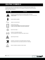
1
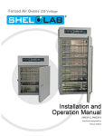
Clean Room Oven 220 – 240 Voltage Installation and Operation Manual SMO5CR-2 Previously designated as CR1-2 SHEL LAB Clean Room Oven 220 - 240 Voltage Installation and Operation Manual Part Number (Manual): 4861580 Revision: November 5, 2015 This oven requires permanent connect wiring (also known as hardwiring. It does not connect to a wall power source using a plug-in power cord. These units are TÜV listed as high performance ovens for professional, industrial, or educational use where the preparation or testing of materials is done at an ambient air pressure range of 22.14 – 31.3 inHg (75 – 106 kPa), with no flammable, volatile, or combustible materials being heated. These units have been tested to the following requirements: CAN/CSA C22.2 No. 61010-1:2012 CAN/CSA C22.2 No. 61010-2-010:2004 Reaffirmed: 2014-07 UL 61010-1:2012-05 UL 61010A-2-010:2002-03 EN 61010-1:2010 EN 61010-2-010:2014 Supplemented by: UL 61010-2-010:2015 2|Page This page left blank 3|Page TABLE OF CONTENTS INTRODUCTION........................................................................................................................................... 6 General Safety Considerations ................................................................................................................. 6 Engineering Improvements ....................................................................................................................... 7 Contacting Assistance ............................................................................................................................... 7 Temperature Reference Sensor Device ................................................................................................... 7 RECEIVING YOUR OVEN ............................................................................................................................ 8 Inspecting the Shipment ............................................................................................................................ 8 Recording Data Plate Information ............................................................................................................. 8 Orientation ................................................................................................................................................. 9 INSTALLATION .......................................................................................................................................... 10 Ambient Conditions ................................................................................................................................. 10 Selecting a Location ................................................................................................................................ 10 Power Source Requirements .................................................................................................................. 11 Power Feed Wiring .................................................................................................................................. 11 Lifting and Handling ................................................................................................................................ 12 Leveling ................................................................................................................................................... 12 Install the Oven ....................................................................................................................................... 12 Initial Cleaning ......................................................................................................................................... 12 Shelving Installation ................................................................................................................................ 13 GRAPHIC SYMBOLS ................................................................................................................................. 14 CONTROL PANEL OVERVIEW ................................................................................................................. 16 OPERATION ............................................................................................................................................... 18 Operating Precautions ............................................................................................................................ 18 Theory of Operations .............................................................................................................................. 20 Preparing the Oven for Use .................................................................................................................... 22 Set the Over Temperature Limit .............................................................................................................. 23 Set the Temperature Controller Set Point ............................................................................................... 23 HEPA Filter Burn-In ................................................................................................................................. 24 Temperature Accuracy Verification ......................................................................................................... 26 Closed Vents ........................................................................................................................................... 28 Over Temperature Limit Active ............................................................................................................... 28 Programmed Operations ......................................................................................................................... 29 Positive Venting of Exhaust .................................................................................................................... 29 USER MAINTENANCE ............................................................................................................................... 32 Cleaning and Disinfecting ....................................................................................................................... 32 Electrical Components ............................................................................................................................ 33 Door Gaskets and Chamber Integrity...................................................................................................... 33 HEPA Filter Lifespan ............................................................................................................................... 33 Replacing the HEPA Filter Assembly ...................................................................................................... 34 Calibrate the Temperature display .......................................................................................................... 36 UNIT SPECIFICATIONS............................................................................................................................. 40 Weight ..................................................................................................................................................... 40 Dimensions .............................................................................................................................................. 40 Capacity .................................................................................................................................................. 40 Shelf Capacity by Weight ........................................................................................................................ 40 Temperature ............................................................................................................................................ 41 Airflow Performance ................................................................................................................................ 41 4|Page Power ...................................................................................................................................................... 41 REPLACEMENT PARTS............................................................................................................................ 42 5|Page INTRODUCTION Thank you for purchasing a Sheldon Manufacturing Clean Room Oven. We know that in today’s competitive marketplace, customers have many choices when it comes to constant temperature equipment. We appreciate you choosing ours. Our continued reputation as a leading laboratory product manufacturer rests with your satisfaction. Sheldon Manufacturing, Inc. stands behind our products, and we will be here if you need us. These ovens are intended for professional, industrial, and educational clean room applications requiring horizontal shelf space airflows. The ovens are not designed for use at hazardous or household locations. Before you use your oven read this entire manual carefully to understand how to install, operate, and maintain the oven in a safe manner. Keep this manual available for use by all oven operators. Ensure that all operators are given appropriate training before the oven begins service. GENERAL SAFETY CONSIDERATIONS Note: Failure to follow the guidelines and instructions in this manual may create a protection impairment by disabling or interfering with the unit’s safety features. This can result in injury or death. Your oven and its recommended accessories have been designed and tested to meet strict safety requirements. For continued safe operation of your oven, always follow basic safety precautions including: Follow all local or regional ordinances in your area regarding the use of this unit. If you have any questions about local regulations, please contact the appropriate agency. Use only approved accessories. Do not modify system components. Any alterations or modifications to your oven may be dangerous and will void your warranty. Always hardwire the unit’s power feed to a single phase, earth grounded electrical source that conforms to national and local electrical codes. If the unit is not grounded, parts such as, knobs and controls may conduct electricity and cause serious injury. Avoid damaging the power feed. Do not bend it excessively, step on it, place heavy objects on it. A damaged power feed can easily become a shock or fire hazard. Never use a power feed after it has been damaged. Do not position the equipment in such a manner as to make it difficult to disconnect or uncouple the power feed. Do not attempt to move the unit while in operation or before the unit has cooled. 6|Page INTRODUCTION (CONTINUED) ENGINEERING IMPROVEMENTS Sheldon Manufacturing continually improves all of its products. As a result, engineering changes and improvements are made from time to time. Therefore, some changes, modifications, and improvements may not be covered in this manual. If your unit’s operating characteristics or appearance differs from those described in this manual, please contact your Shel Lab dealer or customer service representative for assistance. CONTACTING ASSISTANCE If you are unable to resolve a technical issue with the oven, please contact Sheldon Technical Support. Phone hours for Sheldon Technical Support are 6am – 4:30pm Pacific Coast Time (west coast of the United States, UTC -8). Please have the following information ready when calling or emailing Technical Support: the model number and the serial number. These will be found on the unit’s data plate, which is located on the back of the unit at the top right, next to the power supply as mandated by regulatory requirement. EMAIL: [email protected] PHONE: 1-800-322-4897 extension 4, or (503) 640-3000 FAX: (503) 640-1366 Sheldon Manufacturing INC. P.O. Box 627 Cornelius, OR 97113 TEMPERATURE REFERENCE SENSOR DEVICE The oven does not come with a temperature reference device. A reference sensor device must be purchased separately for performing accuracy verifications and calibrations of the oven temperature display. The reference device must be accurate to at least 2°C, and should be regularly calibrated, preferably by a third party. For best results, use a digital device with wired-connected temperature sensing probe. For example: a wire thermocouple probe that can be introduced into the oven chamber, leaving the device outside. Readings taken from outside the unit avoid chamber door openings during verifications and calibrations, and eliminate subsequent waits for the chamber temperature to restabilize before proceeding. Select a probe suitable for the application temperature you will be calibrating or verifying the display accuracy at. Alcohol thermometers are insufficient for conducting accurate verifications and calibrations. Do not use a mercury thermometer. Never place a mercury thermometer in the oven chamber. 7|Page RECEIVING YOUR OVEN Before leaving our factory, all Clean Room Ovens are packaged in high-quality shipping materials to provide protection from transportation-related damage. When an oven leaves our factory, safe delivery becomes the responsibility of the carrier. Damage sustained during transit is not covered by the oven’s warranty. When you receive your High Performance Oven, inspect it for concealed loss or damage to its interior and exterior. If you find any damage to the oven follow the carrier’s procedure for claiming damage or loss. INSPECTING THE SHIPMENT Carefully inspect the shipping carton for damage. Report any damage to the carrier service that delivered the oven. If the carton is not damaged, open the carton and remove the contents. The unit should come with an Installation and Operation Manual, warranty card, a Certificate of Compliance, and the Programming Guide – Watlow EZ-Zone Heating Profiles. Verify that the correct number of shelves, shelf slides, and leveling feet have been included (see the following table for quantities). Included accessories Shelves (2) Shelf Slides (4) Leveling Feet (4) Carefully check all packaging before discarding. Save the shipping carton until you are certain that the unit and its accessories function properly. RECORDING DATA PLATE INFORMATION Locate the data plate on the back of the oven next to the power inlet. The data plate contains the oven model number and serial number. Enter this information below for future reference. Date Plate Information Model Number Serial Number 8|Page 39RECEIVING (CONTINUED) ORIENTATION Permanent Connect Wire Braid 14 gauge, 6 inches (15 cm) Back Panel External Power Outlet Fuse Holders Nitrogen Gas Inlet Note: The external power outlet type varies by country and voltage. Intake Vent Control Panel Exhaust Vent Power Switch Exhaust Vent Valve Control Intake Vent Valve Control Chamber Ceiling Liner Door Latch Left Wall Chamber Liner Outer Door Gasket HEPA Filter Assembly Right Wall Chamber Liner Chamber Gasket Door Latch Figure 1: Orientation Photo 9|Page INSTALLATION Installation of an SMO5CR-2 requires permanent connect wiring (commonly known as hardwiring), and must be performed by a qualified electrical technician. All other installation steps can be performed by the end user. AMBIENT CONDITIONS This oven is intended for use indoors, at room temperatures between 15C and 40C (59F and 104F), at no greater than 80% Relative Humidity (at 25C / 77F). Allow a minimum of 12 inches (30cm) between the oven and any walls or partitions, and 24 inches (60cm) of vertical headspace clearance above the top of the oven for unobstructed airflow and cooling. If the oven exhaust will be vented from the workspace through a duct or other channeling, 12 inches (30cm) of vertical clearance will suffice. Make sure the intake and exhaust vent remain unobstructed. Do not place objects on top of oven, aside from the power exhaust accessory described in the manual. Operating the unit outside of these conditions may adversely affect the oven temperature range and stability. For conditions outside of those listed above, please contact your distributor or Sheldon Sales to explore other ovens suited to your laboratory or production environment. SELECTING A LOCATION When selecting a location to install the oven, consider all conditions that can affect temperature performance. For example: Ovens, autoclaves, and any device that produces significant radiant heat Heating and cooling ducts, or other sources of fast moving air currents High-traffic areas Direct sunlight 10 | P a g e INSTALLATION (CONTINUED) POWER SOURCE REQUIREMENTS When selecting a location for the oven, check that each of the following requirements are satisfied: The oven must be positioned so that all operators have access to the power feed disconnect in case of emergencies. o The Disconnect must be in close proximity to the equipment and within easy reach of the operator. o The Disconnect must be marked as the disconnecting device for the equipment. The power source must be single (1) phase and protective earth grounded. The power source must match the voltage and ampere requirements listed on the oven data plate. This oven is intended for 220 - 240 volt, 50/60 Hz applications at 12 Amps. The power source for the oven must conform to all national and local electrical codes. Supplied voltage must not vary more than 10% from the data plate rating. Damage to the oven may result if supplied voltage varies more than 10%. A separate circuit is recommended to prevent possible loss of product due to overloading or failure of other equipment on the same circuit. A switch or circuit-breaker must be used in the building installation. The required circuit-breaker is 20 Amps Fuses: The oven is provided with (2) two 20 amp fuses. These are located in holders adjacent to the power feed braid on the back power panel of the unit. The fuses protect against overcurrent conditions related to the operation of the oven. If one fuse blows, the oven will shut down. For safe operation, the cause of a blown fuse should be determined prior to replacing it. The oven is also provide with a pair (2) of 2 amp fuses installed adjacent to the external power outlet. Please see the Orientation photo on page 9. The fuses protect against overcurrent conditions related to the operation of the outlet and an attached power exhaust blower. If one fuse blows, the outlet will depower. The cause of a blown fuse should be determined prior to replacing it. POWER FEED WIRING The oven comes provided with an integral 6 inch (15 cm) wire braid of two 14 gauge hightemperature (300°C) hot wires and a 14 gauge earth ground. See the Orientation Picture on page 9. The wires for power source connection should be Green/Yellow – Earth; Black – Hot; Red – Hot. The oven must be earth grounded using the protective conductor terminal (green with yellow stripe wire. Do not remove the protective conductor (earth connection). Removing the protective conductor will negate the oven’s protections against potentially dangerous electric shocks and create a possible fire hazard. 11 | P a g e INSTALLATION (CONTINUED) LIFTING AND HANDLING The oven is heavy. Use appropriate lifting devices that are sufficiently rated for these loads. Follow these guidelines when lifting the oven: Lift the oven only from its bottom surface. Doors, handles, and knobs are not adequate for lifting or stabilization. Restrain the oven completely while lifting or transporting so it cannot tip. Remove all moving parts, such as shelves and trays, and secure the door in the closed position during transfers to prevent shifting and damage. LEVELING The oven must be level and stable for safe operation. Each Clean Room Oven ships with four leveling feet. Insert one leveling foot into each of the four holes in the bottom corners of the oven. Stand the oven upright. Then, adjust the foot at each corner until the oven stands level and solid without rocking. To raise a foot, turn it in a counterclockwise direction; to lower a foot, turn it in a clockwise direction. Note: To prevent damage when moving the oven, turn each of the four leveling feet completely clockwise. INSTALL THE OVEN Install the unit in a workspace location that meets the criteria discussed in the previous entries of the Installation section. After wiring the oven to its power source, only energize the unit for brief periods as necessary to test the wiring power feed and source. INITIAL CLEANING The unit was cleaned at the factory, but not sterilized. Additionally, it may have been exposed to contaminants en route during shipping. See the Cleaning and Disinfecting topic in the User Maintenance section (page 32) for more information on how to clean and disinfect the oven chamber. Remove all wrappings and coverings from shelving prior to cleaning and installation. 12 | P a g e INSTALLATION (CONTINUED) SHELVING INSTALLATION The horizontal airflow within the chamber moves from the HEPA filter housing on the right-hand side of the chamber, to the large holes on the left side. Place the shelves so they do not obstruct the duct holes on the left in order to maximize airflow across the shelf space. 1. Install shelf slide hangers on opposites of the oven by inserting the slider’s tabs into the chamber’s mounting slots, then pushing down gently to secure the slider. 2. Hang the shelf from the two installed sliders. Figure 2: Installed Sliding Shelf 13 | P a g e GRAPHIC SYMBOLS The oven is provided with multiple graphic symbols on its external and internal surfaces. The symbols identify hazards and the functions of the adjustable components, as well as important notes found in the user manual. Symbol Definition Indicates that you should consult your user manual for further instructions. Indique que l'opérateur doit consulter le manuel d'utilisation pour y trouver les instructions complémentaires. Indicates Adjustable Temperature Indique température réglable Indicates AC Power Repère le courant alternative Indicates I/ON and O/OFF I repère de la position MARCHE de l'interrupteur d'alimentation O repère de la position ARRÊT de l'interrupteur d'alimentation Indicates protective earth ground Repère terre électrique Indicates UP and DOWN respectively Touches de déplacements respectifs vers le HAUT et le BA Indicates a Potential Shock Hazard Signale danger électrique Indicates the unit should be recycled (Not disposed of in land-fill) Indique l’appareil doit être recyclé (Ne pas jeter dans une décharge) Indicates: Caution hot surface Indique: Avertissement symbole de surface chaude 14 | P a g e GRAPHIC SYMBOLS (CONTINUED) This page left blank 15 | P a g e CONTROL PANEL OVERVIEW Figure 3: Control Panel Power Switch The green, light up power switch controls all power to the oven. It must be in the illuminated I (ON) position before any systems or components are operational. Temperature, Profile, and OTL Controller The temperature controller for the oven is labeled TEMPERATURE AND HIGH LIMIT CONTROL and consists of a Watlow EZ-Zone Controller. The controlller is provided with a digital display and Up and Down arrow keys. The keys are used to change the oven temperature set point, perform calibrations, and program heating profiles. The arrow keys also control the operations of the Over Temperature Limit system (OTL). Figure 4: Temperature Controller The EZ1 button is used to quick launch Profile 1 or abort any running heating profile (see the Programmed Operations section on page 29). The EZ2 button does not have a function in the SMO5CR-2. The green advance button is used to scroll forward through menus and parameters lists. The reset button is used to scroll the display back to a previous page or menu while programing heating profiles. Pressing the reset button repeatedly returns the display to the home page. Note: On some older Watlow Controllers the Reset button may be labeled with an infinite ∞ symbol rather than RESET. A small flashing “2” toward the center bottom of the display indicates when the controller is powering the oven’s heating elements. A small flashing “1” indicates internal communications functions within the controller. 16 | P a g e CONTROL PANEL OVERVIEW (CONTINUED) Vent Valves The SMO5CR-2 comes provided with two vent valve controls on its front control panel. These open or close the intake and exhaust valves located on the top of the unit. Purge Valve The SMO5CR-2 comes with a purge valve located on the back of the unit. The valve can be connected to a cylinder of nitrogen (N2) or other neutral gas to purge the oven chamber. 17 | P a g e OPERATION OPERATING PRECAUTIONS Warning: This SMO oven is not an explosion-proof unit! Avertissement: Ce sont des fours pas résistants aux explosions. 1. The oven is not designed to safely contain combustible gasses. 2. Do not place explosive, combustible, or flammable materials into the chamber. 3. The bottom surface of the chamber should not be used as a work surface. 4. Do not operate the oven in an environment with noxious fumes. 5. The SMO oven is provided with a dampened exhaust vent. For safe and efficient oven operation follow these precautions: a. In normal heating the damper is closed. b. Outgassed byproducts may be hazardous to or noxious for operating personal. If either is the case, the oven exhaust should be positively ventilated to a location outside workspace in accordance with national and local regulations. 6. Do not place sealed or filled containers in the oven. 7. Do not place mercury thermometers in the oven. 8. The SMO oven is not designed for use in Class I, II, or III locations as defined by the US National Electric Code. Warning: The vent dampers may be hot to the touch. These areas are marked with Hot Surface labels. Proper PPE should be employed to minimize burn risk. Avertissement:Les clapets d'aération peuvent être chauds au toucher. Ces zones sont marqués avec des étiquettes de Surface chaude. Les EPI approprié devraient être employée pour réduire au minimum le risque de brûler. 18 | P a g e OPERATION (CONTINUED) This page left blank 19 | P a g e OPERATION (CONTINUED) THEORY OF OPERATIONS To achieve the oven’s stated operation specs, the vents must be fully closed. Operating the oven with the vents open impacts the oven chamber temperature uniformity and stability. This may or may not speed drying rates, depending on the nature of your samples or product. During normal operations the vents are intended to be opened only while the product or samples are cooling. Running the oven with an active power exhaust blower attached to the exhaust vent will reduce the oven chamber temperature. Heating The oven comes from the factory set to run in its manual mode. When powered and running in manual mode, the SMO oven chamber will heat to and then indefinitely maintain the temperature set point shown on the home page of the controller. This manual mode set point can be adjusted by the end-user using the temperature controls. The oven will not heat if the temperature set point is set below its operational temperature range. When the oven is powered, the chamber air temperature cannot go below the ambient room temperature plus the internal waste heat of the oven. Waste heat is generated primarily by the operation of the air-circulating blower fan motor and the resulting air compression in the duct spaces. In practice the temperature floor is ambient +15°C. The oven heater controller (a Watlow EZ digital controller) stores the user-selected temperature set point, along with any user-programed heating profiles. The controller monitors the oven chamber air temperature using a solid-state probe located in the airstream on the right wall of the chamber. When the processor detects that the chamber temperature has dropped below the current temperature set point, it pulses power to a heating element in a recirculation air duct located above the oven chamber. SMO ovens rely on natural heat radiation for cooling. The oven depends on the operation of its blower fan to circulate air and maintain temperature uniformity and stability in the chamber. The controller employs proportional-integral-derivative analytical feedback-loop functions when measuring and controlling the chamber air temperature levels. PID-controlled heating pulse intensities and lengths are proportional to the difference between the measured chamber temperature and the current set point. The frequency of pulses are derived from the rate of change in the difference. The integral function slows the rate of pulses when the temperature nears the set point to avoid overshooting. The heating rates given in unit specification section of this manual are for a 25°C environment. The ambient temperature of the workspace around the oven will affect heating and cooling. 20 | P a g e OPERATION (CONTINUED) Heating Profiles The Watlow controller can store up to four heating profiles, each with ten steps. Please see the Programed Operations section on page 29, and the Watlow EZ-Zone Profile Programing Guide for more details. A profile can be launched whenever the unit is running in manual mode. Heating profiles should allow adequate time for the oven chamber to heat to the first temperature in the profile, prior to continuing to the second step of the profile. Airflow and Applications During normal operations an internal blower fan motor pulls air out of the oven chamber through perforations on the left chamber wall. The captured air is pulled up and blown across a heating element in the recirculation duct immediately above the chamber, then forced down through a duct on the right side of the chamber. The air exits the duct through the HEPA filter mounted on the right chamber wall. Upon leaving the filter, the heated air blows horizontally across the shelf space, helping to create temperature uniformity and enhance drying. After crossing the shelves, the air enters a duct on the left side of the chamber, and is then pulled back into the heater space above the oven chamber. If either or both the intake and exhaust vents are opened, air will exit through the open exhaust vent on the top right of the unit. Lost air will be replaced through the intake vent. The rate of atmosphere exchange depends on several variable factors. These include: ambient conditions, position of the vent valves, the volume of material in the oven chamber, and if a power exhaust unit is connected to the exhaust vent. A purge valve is located on the back of the unit. This valve can be connected to a nitrogen (N 2) source or other neutral gas source for purging the oven chamber. Over Temperature Limit The Watlow controller contains a backup temperature control system with independent circuitry. This system connects to a redundant temperature sensor probe inside the oven chamber. The over temperature heating cutoff system is intended to be set 5°C above your application or process temperature set point. In the event the oven chamber temperature exceeds the over temperature limit setting, the backup system will depower the heating element. This provides redundant heating control the event of a failure of the primary circuitry or the main temperature sensor probe. 21 | P a g e OPERATION (CONTINUED) PREPARING THE OVEN FOR USE Preform the following steps to prepare the oven for use after installing it in a new workspace environment. Note that it will take approximately 13 hours to run the bur-in procedure for the HEPA filter. Optional: If you will be performing a temperature display accuracy verification as part of your set up, Sheldon Manufacturing recommends introducing the temperature probe of your temperature reference device into the oven chamber now, prior to powering the oven. Please see the procedure (page 26) for probe placement instructions. Placing the probe now offers significant times savings during the procedure. The probe must be rated for the temperature you will be running the oven at during the burn-in (see page 22). 1. Open the intake and the exhaust vents on the oven to prepare for the initial burn-in procedure. 2. Place the Power Switch in the ON position. The Temperature Display will illuminate, then show the controller home page. 3. Set up the oven for use by carrying out the following procedures found in this manual’s Operation section: a. Set the Over Temperature Limit to 325°C (page 23) Set to the control’s maximum setting in order to prevent it from interfering with the next three procedures. Home Page Chamber Air Temperature in Red Set Point in Green b. HEPA Filter Burn-In (page 24) Set the Temperature Controller Set Point to 125°C to start running the Burn-In procedure manually (page 23). – Or – Program a heating profile to automatically run the Burn-In. See pages 25 and 29, as well as the Programing Guide – Watlow EZ-Zone Controller Heating Profiles, which came with the oven. c. Optional: Perform a Temperature Display Accuracy Verification (page. 26) d. Set the Temperature Controller Set Point on the home page to your application temperature, if you will be running the oven in its manual mode (page 23). Otherwise, program a heating profile (page 29). e. Set the Over Temperature Limit (page. 23) This time set the control to 5°C above your application manual mode temperature or the highest temperature of your heating profile. This prepares the oven for normal use. f. Load the oven with your product or samples. End of procedure 22 | P a g e OPERATION (CONTINUED) SET THE OVER TEMPERATURE LIMIT This procedure sets the Over Temperature Limit backup system. Normally the system is set 5°C above the highest set point temperature you will be using during your current application or process. Always set at least 5°C above the hottest temperature of a heating profile. Note: If this is the first use of the oven, set the Over Temperature Limit to 325°C or higher to prepare to help ensure the OTL system will not interfere with the Burn-In procedure. 1. Press the green Advance button until “Lh.S1” (Limit High Set Point) shows in the greencolored mid-level display. Step 1 and 2: Limit set at 325°C 2. Use the Up and Down arrows to enter a temperature limit in the red top display. 3. After entering the temperature limit, press the Advance button. The red display will show “SAFE”, indicating that the temperature limit has been set. 4. Press the Reset button to scroll the display back to the home page. Step 3 SET THE TEMPERATURE CONTROLLER SET POINT This procedure sets a new temperature set point for the oven’s manual mode. Note: Set the oven to 125°C if you will be manually running the HEPA Filter Burn-In procedure prior to its first use (see page 24).This procedure may also be run by programing and launching it as a heating profile. 1. On the home page, use the Up and Down Arrow keys to adjust the set point in the green display to your baking application or process temperature set point. a. Holding down an arrow key will cause the temperature to advance in increments of ten (10) rather one (1). Step 1: Set Point at 0 2. Release the Arrow Button once you have reached your required set point. There may be a brief pause before the oven starts heating. a. A small flashing 2 in the Watlow display indicates when the temperature controller is calling for heat. End procedure 23 | P a g e OPERATION (CONTINUED) HEPA FILTER BURN-IN A HEPA filter must be burned in prior to its first use. The HEPA filter will fill with gas and produce significant smoke during the burn-in. The oven’s intake and exhaust vents must be open throughout the procedure. The burn-in process requires approximately thirteen hours. Remove shelving from the oven prior to the burn-in. Burn-in: 1. 125°C for 1 hour 2. 150°C for 4 hours 3. 175°C for 1 hour 4. 200°C for 1 hour 5. 225°C for 1 hour 6. 250°C for 1 hour If your operating temperature will exceed 250°C, continue the cycle for one hour for each increasing 25°C increment, until your operating temperature is reached (maximum 300°C). The filter must be burned-in to the highest operating temperature. If manually running the burn-in process, allow time for the oven to ramp up (heat) to each temperature level and ramp down (cool) afterward. Under most ambient conditions a-half hour (30 minutes) should suffice for ramping up. Procedure continued on next page 24 | P a g e OPERATION (CONTINUED) Burn-In Heating Profile The table below shows the burn-in process as a programed heating profile for the Watlow controller in a 25°C ambient environment. Please consult the Programing Guide – Watlow EZ-Zone Controller Heating Profiles document for the details of how to program a heating profile. Step Step Type Step 1 Time Interval “Ti” Step 2 Soak “SoAh” Step 3 Time Interval “Ti” Step 4 Soak “SoAh” Step 5 Time Interval “Ti” Step 6 Soak “SoAh” Step 7 Time Interval “Ti” Step 8 Soak “SoAh” Step 9 Time Interval “Ti” Step 10 Soak “SoAh” Step 11 Time Interval “Ti” Step 12 Soak “SoAh” Step 13 End Set Point 125°C 150°C 175°C 200°C 225°C 250°C Time Interval Event Option 30 Minutes Off 1 Hour Off 30 Minutes Off 4 Hours Off 30 Minutes Off 1 Hour Off 30 Minutes Off 1 Hour Off 30 Minutes Off 1 Hour Off 30 Minutes Off 1 Hour Off Off Post-Burn Cleaning: Note: Do not remove or disturb the HEPA filter assembly cover after the burn-in. A burnt filter is fragile and easy to damage. Only remove the HEPA filter housing cover when replacing the filter. 1. Shutdown the oven. Allow the oven to cool to room temperature. 2. Clean the interior surfaces to remove the exhaust from the HEPA filter. a. Take care not to damage the temperature sensor probes when cleaning. These are located on the back wall of the oven chamber, adjacent to the HEPA filter. 25 | P a g e OPERATION (CONTINUED) TEMPERATURE ACCURACY VERIFICATION Note: Performing an accuracy verification of the temperature display requires a temperature reference device. Please see the Reference Sensor Devices entry on page 7 for device requirements. Optional: A verification of the temperature display accuracy may be carried out when preparing the oven for use, if required by your laboratory or production protocol. The verification compares the displayed temperature of the oven chamber with the actual temperature of the chamber air as provided by a reference sensor device. If a difference between the actual and displayed temperatures is discovered, perform a temperature calibration. Please see the Calibrate Temperature Display procedure on page 36 in the User Maintenance section. Close the Vents Figure 3: Damper in Closed Position Both the intake and exhaust vents must be closed in order to perform an accurate temperature verification. Chamber temperature uniformity and stability will be too unstable when operating with the vents open to verify the accuracy of the oven temperature display. Probes A reference device sensing probe may be introduced through the through the chamber door space. Use heat-resistant, non-marking tape to secure the wires to the body of the incubator, and seal any gaps in the door space. The door must close and latch fully. Figure 4: Probe End 2 inches (5cm) From Shelf Surface Place the sensor probe of the temperature reference device as close as possible to the geometric center of the oven chamber. A thermocouple sensor probe sleeve may be taped to the shelving, as long as the exposed copper end is 2 inches (5cm) away from the shelf (see Figure 4). An exposed sensor probe in direct contact with the shelving may experience heat sinking, which can result in an inaccurate temperature reading. Pre-Heating Verify that the oven is set to your application or baking procedures set point. Let the oven heat to the set point temperature and run for at least 1 hour undisturbed in order to stabilize. Temperature Stability The oven chamber is thermally stabilized when no fluctuations of ±2.0C or greater have been detected with the verification reference device for a minimum of 30 minutes. Failure to wait for stabilization will result in a failure to verify the accuracy of the oven temperature display reading. 26 | P a g e OPERATION (CONTINUED) Note: If you have not done so already, set the OTL limit to 325°C to prevent the OTL heating cutoff from interfering with the verification process. Please see the Set Over Temperature procedure on page 23. Verifying the Temperature Display Accuracy 1. Once the chamber temperature has stabilized, compare the reference device and the oven display temperature readings. Reference Device a. If the readings are the same, or the difference between the two (2) falls within the acceptable range of your protocol, the display is accurately showing the oven chamber air temperature. The Temperature Verification procedure is now complete. a. See step 2 if a difference falls outside the acceptable range of your protocol. Reference Device 2. Perform a temperature calibration to match the controller display to the actual chamber temperature if a difference falls outside your protocol range. a. Please see 36 in the User Maintenance section. End of procedure 27 | P a g e OPERATION (CONTINUED) CLOSED VENTS The unit is intended to be run with both vents closed in ordered to achieve its stated operating temperature specifications. The unit can be run with one or both vents open, however, the oven may not achieve its stated chamber uniformity, stability, or heating or recovery times. Drying times are dependent on the nature of your product or samples, as well as the volume placed in the oven chamber. OVER TEMPERATURE LIMIT ACTIVE When the oven chamber air temperature exceeds the user-programed Over Temperature Limit, the OTL system will depower the heating elements. This is normally accompanied by a mechanical click. A small “4” will show in the bottom display, indicating that the controller in rerouting power away from the heating elements. Two alternating alert screens will flash, indicating a failure and that the Limit High One (LiH1) alert has been activated. The Over Temperature Limit will activate if one of two events happens: You have set the Over Temperature Limit below the temperature set point you are using for your application or process. The main controller circuitry or sensor probe has failed, and must be replaced in order to maintain safe and accurate oven operations. Alternating OTL Alert Screens If you have set the Over Temperature Limit too low, perform the following steps to take the unit out of shutdown: 1. Press the advance key until Ignore “i9nr” shows in the top display, and Limit High “Lih1” in the green display. 2. Press the green advance key again. Limit High Set Point “LhS1” will appear in the green display, and the Over Temperature Limit setting in the red top display. Step 1 3. Adjust the Over Temperature Limit to above your set point using the Up Arrow Button. 4. Push the Reset Button to save the new OTL setting. If the Over Temperature Limit has activated and the red oven temperature is higher than your green temperature set point, the main controller circuitry or temperature sensor may have failed. Cease using the oven and contact Sheldon Technical Support for assistance. Step 3 28 | P a g e OPERATION (CONTINUED) PROGRAMMED OPERATIONS The Watlow controller can hold four (4) ten-step heating profiles. Additionally, profiles may be combined by programing profile steps sequentially to run as a single profile of between two (2) and forty (40) steps. Please see the Programing Guide – Watlow EZ-Zone Controller Heating Profiles document that comes included with the oven for instructions on how to program heating profiles. The guide is intended as simplified explanation for all major heating profile functions and programing steps. The guide is also available on the Shel Lab website in PDF format. Refer to Chapter 7 of the “EZ-Zone PM User’s Manual” for highly detailed instructions on how to program the EZ Watlow Controller. POSITIVE VENTING OF EXHAUST Exhaust ducting can be connected to the oven exhaust port to channel or positively vent exhaust out of the workspace around the oven. An exhaust duct should not extend straight up from the oven. Rather it should include a steep bend sufficient to stop condensation in the ducting from sliding or falling down into the oven. The exhaust is powered and then turned off as steps in a programed heating profile. It will not run while the oven is in the manual mode, if plugged into the oven. Sheldon Manufacturing sells a 220 - 240 volt High Performance Power Exhaust that can be mounted directly on the exhaust vent, and powered by the oven. Note: The power exhaust (9990741) has painted surfaces and may not be suitable for use in a clean room environment. Mounting the Power Exhaust Figure 5: High Performance Power Exhaust (Part Number 9990741) 1. Remove the screws on the cover of the exhaust vent assembly on the top of the oven, but leave the assembly in place. 2. Mount the power exhaust blower on the exhaust vent cover assembly, aligning the blower and the assembly’s screw holes. The open side of the blower’s mounting body should go over the handle of the exhaust port’s sliding vent cover. 3. Reinstall the screws. 4. Plug in the power exhaust into the 220 - 240 volt, NEMA 5-20R outlet on the back of the oven. Continued on next page 29 | P a g e OPERATION (CONTINUED) Activating and Deactivating the Power Exhaust To activate the power exhaust as part of a heating profile step, do the following: 1. While selecting the parameters for the step, choose Event 1 On (“Ent1” “on”). a. The Event 1 parameter is located after the Time parameter when scrolling through a step menu using the green Advance Key. Step 1a b. Use either of the Arrow Keys to toggle “oFF” to “on”. 2. Press the Advance key to scroll to the next event and save Event 1 as On. 3. Next time the profile runs, the 220 - 240 volt outlet on the back of the oven will power up when the controller reaches this step. 4. The plugged in power exhaust will run until the next step in which Event 1 Off is selected (“Ent1” “oFF”), or until the oven shuts down. 5. By default the Event 1 parameter is set to Off. It must be switched to On for each successive step that you want the blower to run during the execution of the profile. 30 | P a g e Step 1b OPERATION (CONTINUED) This page left blank 31 | P a g e USER MAINTENANCE Warning: Prior to maintenance or service on this unit, disconnect the power feed from the power supply. Avertissement: Avant d'effectuer toute maintenance ou entretien de cet appareil, débrancher le cordon secteur de la source d'alimentation. CLEANING AND DISINFECTING If a hazardous material or substance has spilled in the oven, immediately initiate your site’s Hazardous Material Spill Containment protocol. Contact your local Site Safety Officer and follow instructions per the site policy and procedures. The unit should be cleaned prior to first use. Do not use spray-on cleaners or disinfectants. These can leak through openings and coat electrical components. Do not use cleaners or disinfectants that contain solvents capable of harming paint coatings or stainless steel surfaces. Do not use chlorine-based bleaches or abrasives; these will damage the chamber liner. Consult with the manufacturer or their agent if you have any doubts about the compatibility of decontamination or cleaning agents with the parts of the equipment or with material contained in it. Warning: Never clean the oven with alcohol or flammable cleaners. Avertissement: Ne jamais nettoyer l'appareil à l'alcool ou avec des nettoyants inflammables. Cleaning Perform the steps below to clean the oven: 1. Remove all removable interior components such as, shelving and accessories. 2. Clean the oven with a mild soap and water solution, including all corners. Do not use an abrasive cleaner that will damage stainless steel surfaces. Do not use deionized water to rinse or clean with. 3. Rinse with distilled water and wipe dry with a soft cloth. 4. Take special care when cleaning around the temperature sensor probes at the back of the chamber to prevent damage. Disinfecting Cary out the following steps to disinfect the oven, if required by your laboratory or production protocol: 1. Turn the unit off. Carry out your disinfection protocol. 2. If allowed by your protocol, remove all shelving. Disinfect all corners. Take special care not to damage the temperature sensor probes when disinfecting. 3. Disinfect the unit using commercially available disinfectants that are non-corrosive, nonabrasive, and suitable for use on stainless steel surfaces. Contact your Site Safety Officer for detailed information on the disinfectants compatible with your study or production protocol. 32 | P a g e MAINTENANCE (CONTINUED) ELECTRICAL COMPONENTS Electrical components do not require maintenance. If the oven fails to operate as specified, please contact your Shel Lab distributor or Sheldon Manufacturing Technical Support for assistance. DOOR GASKETS AND CHAMBER INTEGRITY The Sheldon Clean Room Oven is provided with a high temperature silicon door gasket. See the Parts Section on page 35 for ordering replacement gaskets. Periodically, inspect the door latch, trim, catch, and gasket for signs of deterioration. Failure to maintain the integrity of the door system shortens the life span of the Oven. HEPA FILTER LIFESPAN The lifespan of the HEPA filter can vary greatly depending on ambient conditions such as, humidity and temperature, as well as the processes or applications the oven is being used for. The more particulates and oily fumes produced by material drying or baking out in the oven chamber, the faster the filter will become clogged and constrict airflow through the oven. A useable life of one (1) year is common for many cleanroom applications. Replace the filter at least once per year. Replace more often if the exhaust output is noticeably reduced, or if required by your production or laboratory protocol, or regulatory requirements. 33 | P a g e MAINTENANCE (CONTINUED) REPLACING THE HEPA FILTER ASSEMBLY To replace the HEPA filter assembly, it is necessary to remove or at least partly remove the door gasket. Replacing the HEPA filter assembly is an opportune time to replace the door gasket. Note: Door removed in illustrations for clarity. Do not remove the door from the oven. 1. Remove all shelves and shelf sliders from the oven. 2 2. Unscrew the nuts located at the top of the back wall of the oven chamber. Remove the nuts and washers. 3 1 1, 2, 3) Remove Shelves, Nuts, and Door Gasket 3. Remove the chamber gasket so that there is room to pull the ceiling liner out through the door space. The gasket may be fully or partially removed. 4) Ceiling Liner Removed 4 4. Remove the chamber ceiling liner by pulling it out through the oven door space. The liner may require some side-to-side motion to free up. 5. Remove the right wall air duct that the HEPA filter assembly is mounted on by pulling it out through the door space. Procedure continued on next page 34 | P a g e 5 5) Right Air Duct and HEPA Filter Assembly Removed MAINTENANCE (CONTINUED) Mounting Bracket Screw HEPA Filter Pin Nut and Washer 6. Loosen but do not remove the six (6) mounting bracket screws on the right air duct. a. This creates play (looseness) in the mounting bracket that will make it easier to slide out the HEPA filter. 7. Unscrew and remove the 12 HEPA filter pin nuts and washers. 6) Loosen the Mounting Bracket Screws 8. Slide the old HEPA filter assembly out of the air duct’s mounting bracket. 9. Slide the new HEPA filter assembly into the air duct assembly. a. Screw in the 12HEPA filter pin screws and washers. b. Retighten the six (6) mounting bracket screws. 7) Remove the HEPA Filter Pin Nuts and Washers 10. Reinstall the air duct assembly on the right wall. 11. Reinstall the oven chamber ceiling liner. 12. Screw in the back wall nuts and washers to secure the ceiling liner. 13. Reinstall the chamber gasket. End of procedure 8) Slide the HEPA Filter Out of the Air Duct 35 | P a g e MAINTENANCE (CONTINUED) CALIBRATE THE TEMPERATURE DISPLAY Note: Performing a temperature display calibration requires a temperature reference device. Please see the Reference Sensor Devices entry on page 7 for device requirements. Temperature calibrations are performed to match the temperature display to the actual air temperature inside the oven chamber. The actual air temperature is supplied by a reference sensor device. Calibrations compensate for drifts in the controller as well as those caused by the natural material evolution of the sensor probe under temperature in the chamber space. Calibrate as often as required by your laboratory or production protocol, or regulatory compliance schedule. Vents The vent dampeners must be close in order to perform an accurate display calibration. Chamber temperature uniformity and stability are too disrupted when operating with the vents open to verify the accuracy of the oven temperature display. Figure 5: Vent Damper in Closed Position Probes A reference device sensing probe may be introduced through the through the chamber door space. Use heat-resistant, non-marking tape to secure the wires to the body exterior and seal any gaps. The door must close and latch fully. Secure the wiring and cover any gaps in the door space using heatresistant, non-stick tape. Figure 6: Probe End 2 inches (5cm) From Shelf Surface Place the sensor probe of the temperature reference device as close as possible to the geometric center of the oven chamber. A thermocouple sensor probe sleeve may be taped to the shelving, as long as the exposed copper end is 2 inches (5cm) away from the shelf (see Figure 6). An exposed sensor probe in direct contact with the shelving may experience heat sinking, which can result in an inaccurate temperature reading. Pre-Heating Verify that the oven is set to your application or baking procedures set point. Let the oven heat to the set point temperature and run for at least 1 hour undisturbed in order to stabilize. Temperature Stability The oven chamber is thermally stabilized when no fluctuations of ± 2.0C or greater have been detected with the verification reference device for a minimum of 30 minutes. Failure to wait for stabilization will result in an inaccurate calibration and oven temperature display reading. Procedure continued on next page 36 | P a g e USER MAINTENANCE (CONTINUED) Temperature Calibration 1. Once the chamber has stabilized with no fluctuations of 0.2˚C or greater, compare the reference temperature device and chamber temperature display readings. Reference Device a. If the readings are the same, or the difference between the two (2) falls within the acceptable range of your protocol, the display is accurately showing the chamber temperature. The Temperature Verification procedure is now complete. b. See step 2 if a difference falls outside the acceptable range of your protocol. 2. The display requires calibration. Reference Device a. The difference (also known as an error) between the reference device and the display is an offset. b. Examples of offset values: Reference Sensor Reading Oven Temp. Display Offset Value 152.0°C 150°C 2 149.1°C 150°C -0.9 148.0°C 150°C -2 c. Note the offset value. 3. Place the controller display in the Operations selection menu. a. Press and hold both the Up and Down Arrow buttons simultaneously for approximately 3 seconds. b. Release the buttons when “A1” appears in the Upper Display and “Oper” appears in the Lower Display. Operations Selection Menue Continued on next page 37 | P a g e USER MAINTENANCE (CONTINUED) Temperature Calibration (Continued) 4. Advance through the Operations menu to the Temperature Calibration page. a. Push the green Advance button repeatedly unit “i.CA” appears in the green middle display and a number value in the red top display. 5. Adjust the number value in the top display to match the offset value, using the arrow buttons. 6. Save the calibration offset and return to the Home Page. a. Press the Reset Button repeatedly until the display shows the home page. b. The oven will begin to heat or passively cool to reach the current set point with the offset display value. 7. Allow the oven to stabilize after achieving the temperature set point using the offset display value. Continued on next page 38 | P a g e USER MAINTENANCE (CONTINUED) Temperature Calibration (Continued) Reference Device 8. Once the chamber has stabilized (no fluctuations of 0.2˚C or greater) for a half hour, compare the reference temperature device and oven temperature display readings. a. If the readings are the same, or the difference between the two (2) falls within the acceptable range of your protocol, the display is now accurately showing the chamber temperature. The Temperature Verification procedure is now complete. b. See step 9 if a difference falls outside the acceptable range of your protocol again. Reference Device 9. Repeat steps 2 – 8, up to two more times. a. Three calibration attempts may be required to successfully calibrate ovens that are more than ±2°C out of calibration. 10. If the temperature readings difference still falls outside your protocol after three calibration attempts, contact your distributor or Sheldon Technical Support for assistance. End of procedure 39 | P a g e UNIT SPECIFICATIONS The SMO5CR-2 is a 220 - 240 voltage unit. Please refer to the oven’s data plate for individual electrical specifications. Technical data specified applies to ovens with standard equipment at an ambient temperature of 25°C and a voltage fluctuation of ±10%. The temperatures specified are determined in accordance to factory standard following DIN 12880 respecting the recommended wall clearances of 10% of the height, width, and depth of the inner chamber. All indications are average values, typical for units produced in the series. We reserve the right to alter technical specifications at all times. WEIGHT Shipping Net Weight 425 lbs 325 lbs Exterior W × D × H Interior W × D × H 35 x 29 x 38 17 x 20 x 20 DIMENSIONS By Inches By centimeters Exterior W × D × H Interior W × D × H 89 x 73.7 x 96.5 43.2 x 50.8 x 51 CAPACITY Cubic Feet Liters 3.9 110 SHELF CAPACITY BY WEIGHT Pounds Kilograms 50 lbs. per shelf 22.8 kg per shelf 40 | P a g e UNIT SPECIFICATIONS (CONTINUED) TEMPERATURE All temperature performance data for 25°C ambient conditions Range Uniformity Stability Ambient + 20 to 260C + 2C @ 110 0.2°C Heat Up Time to 150°C 35 minutes Recovery to 150°C 5 minutes after closing the door* *After a 30 second door opening AIRFLOW PERFORMANCE Airflow performance data is for both the intake and exhaust vents fully open. Cubic Feet Per Minute Liters Per Minute Air Exchanges Per Hour 6.4 181.23 96 POWER AC Voltage Amperage Frequency Phase 220 - 240 12 50/60 Hz 1 (Single) 41 | P a g e REPLACEMENT PARTS Description Parts Number Adjustable Foot Description Parts Number HEPA Filter Assembly 2700512 Chamber Gasket Silicone (unit of sales is per foot, requires 11 feet) 9990503 Shelf Slide 3450546 Door Gasket SMO5CR2 Silicone (unit of sales is per foot, requires 11 feet) 5121189 Shelf SMO5CR-2 5121195 3450587 Fuse 20 Amp Power Exhaust Blower Unit 220 - 240 Volt 3300538 9990741 Ordering Parts and Consumables If you have the Part Number for an item, you may order it directly from Sheldon Manufacturing by calling 1-800-322-4897 extension 3. If you are uncertain that you have the correct Part Number, or if you need that specific item, please contact Sheldon Technical Support for help at 1-800-322-4897 extension 4 or (503) 640-3000. Please have the model number and serial number of the oven ready, as Tech Support will need this information to match your unit with its correct part. 42 | P a g e This page left blank 43 | P a g e