1
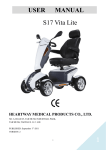
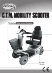
www.drivemedical.co.uk
ST5D
User Manual
ST#5
Instruction Booklet
TABLE OF CONTENTS
INTRODUCTION --------------------------------------------------------1
IMPORTANT PRECAUTIONS ----------------------------------------2
ELECTROMAGNETIC INTERFERENCE AND WARNINGS ----3
IDENTIFICATION OF PARTS ----------------------------------------5
CHARGING THE BATTERIES --------------------------------------11
DISASSEMBLING YOUR SCOOTER -----------------------------12
ASSEMBLING YOUR SCOOTER ----------------------------------13
CARE AND MAINTENANCE ----------------------------------------14
OPERATING YOUR SCOOTER ------------------------------------15
TROUBLESHOOTING ------------------------------------------------17
TECHNICAL SPECIFICATIONS ------------------------------------19
INSPECTION CHECKS ----------------------------------------------20
Issue 1
ST#5
Instruction Booklet
INTRODUCTION
Thank you and congratulation on purchasing your new Drive Medical Ltd. Mobility
Scooter. It is designed to provide you with transportation ability indoors and outdoors.
We pride ourselves on providing safe and comfortable products. Our goal is to ensure
your complete satisfaction. We sincerely hope you enjoy your new Mobility Scooter.
Important symbols in this manual & Product Markings
General risks
This symbol warns you of general hazards!
•Always follow the instructions to avoid injury to the user or damage to the product.
READ WELL BEFORE OPERATION!
This symbol advises you to read information carefully.
This symbol identifies general information which is intended to simplify working
with your product and which refers to special functions.
Please read and observe all warning and instruction provided in owner's manual
before you operate with various convenient function of this scooter. Also, please
retain this booklet for future reference.
The vehicle has been successfully safety-tested to German and international standards.
It was also successfully tested to EN60529 IPX4 for splash water insensitivity, and
is therefore ideally suitable for typical central European weather conditions.
If you are visually impaired, this document can be viewed in PDF format at
www.drivemedical.co.ukm or alternatively is available on request in large text.
Life expectancy
We estimate a life expectancy of five years for this product, provided it is used in
strict accordance with the intended use as set out in this document and all maintenance
and service requirements are met. The estimated life expectancy can be exceeded
if the product is carefully used and properly maintained, and provided technical and
scientific advances do not result in technical limitations. The life expectancy can also
be considerably reduced by extreme or incorrect usage.
The fact that we estimate a life expectancy for this product does not constitute an
additional warranty.
If you have any question, you can contact :
or your local dealer:
Information of European Representative :
EMERGO EUROPE
Molenstraat 15
2513 BH, The Hague
The Netherlands
1
Issue 1
ST#5
Instruction Booklet
IMPORTANT PRECAUTIONS
•This scooter is designed for single person use only at any one time.
•Maximum load is 181 kgs.
•Turn key off before getting on or off.
•Always drive carefully and be aware of others using the same area.
•Always use pedestrian crossings wherever possible. Take extreme care when crossing
roads.
•Do not drive on slope exceeding 10 degree, and take extreme care when turning on slope.
•Do not use full power when turning to sharp corner.
•Take great care and drive in low speed when backing up, riding downhill or on uneven
surface, and climbing curb.
•Please use the lowest speed when driving through the descending road or uneven terrain.
If speed is too fast, leave your hand off the handle bar, let the scooter stop. Make sure
safety and start again.
•The weight capacity limit at different ramp degree (please refer to following picture).
52kg /
10 degree
91kg /
8 degree
136kg /
6 degree
160kg /
4 degree
•The grade climbing degree will be affected by weight capacity, driving speed, and ramp degree, and scooter parameter.
•To prevent any danger from motor defected; please avoid to drive on long ramp or any uneven terrain.
•A slow speed must always be used when ascending, descending or traversing aslope
or incline and also on uneven terrain, ramps and soft or loose surfaces, such as gravel
or grass.
•To prevent any danger, do not turn around at high speed on ascending, descending ramp.
•Scooter may not operate well in high humidity.
•Do not leave the powered scooter in a rain storm of any kind.
•Do not use the powered scooter in a shower.
•Direct exposure to rain or dampness will cause the scooter to malfunction electrically
and mechanically; may cause the powered scooter to prematurely rust.
•Never put scooter in neutral when staying on slopes.
•Follow traffic laws when riding outside.
•When scooter on moving transport vehicles, do not sit or stay on scooter.
Risk of injury from hot surfaces!
Do not leave the mobility device in direct sunlight for prolonged periods. Metal parts
and surfaces such as the seat and armrests can become very hot.
The scooter ST#5D conforms to the following standards :
•requirements for resistance to ignition in accordance with ISO 7176-16
•seat materials used on this product conform to EN1021 parts 1 and 2.
NOTE:
The control system is programmed with standard values in the works. Your Drive
Medical dealer can carry out programming tailored to fit your requirements.
2
Issue 1
ST#5
Instruction Booklet
ELECTROMAGNETIC INTERFERENCE
AND WARNINGS
CAUTION: It is very important that you read this information regarding the possible
effects of Electromagnetic Interference on your motorized scooter.
Powered wheelchairs and motorized scooters may be susceptible to electromagnetic
interference (EMI), which is interfering electromagnetic energy (EM) emitted from sources
such a radio stations, TV stations, amateur radio (HAM) transmitters, two-way radios, and
cellular phones. The interference (from radio wave sources) can cause the motorized
scooter to release its brakes, move by itself, or move in unintended directions. It can also
permanently damage the motorized scooter control system. The intensity of the interfering
EM energy can be measured in volts per meter (V/m). Each motorized scooter can resist
EMI up to a certain intensity. This is called its "immunity level." The higher the immunity
level, the greater the protection. At this time, current technology is capable of achieving
at least a 20 V/m immunity level, which would provide useful protection from the more
common sources of radiated EMI. The immunity level of this motorized scooter model is
not known.
There are a number of sources of relatively intense electromagnetic fields in the everyday
environment. Some of these sources are obvious and easy to avoid. Others are not
apparent and exposure is unavoidable. However, we believe that by following the warnings
listed below, your risk to EMI will be minimized.
The sources of radiated EMI can be broadly classified into three types :
1.Hand-held portable transceivers (transmitters-receivers) with the antenna mounted
directly on the transmitting unit. Examples include: citizens band (CB) radios, "walkie
talkie," security, fire, and police transceivers, cellular telephones, and other personal
communication devices
Some cellular telephones and similar devices transmit signals while
they are ON, even when not being used
2.Medium-range mobile transceivers, such as those used in police cars, fire trucks,
ambulances, and taxis. These usually have the antenna mounted on the outside of the
vehicle; and
3.Long-range transmitters and transceivers such as commercial broadcast transmitters
(radio and TV broadcast antenna towers) and amateur (HAM) radios
Other types of hand-held devices, such as cordless phones, laptop
computers, AM/FM radios, TV sets, CD players, and cassette players,
and small appliances, such as electric shavers and hair dryers, so far as.
we know, are not likely to cause EMI problems to your motorized scooter.
3
Issue 1
ST#5
Instruction Booklet
Motorized Scooter Electromagnetic Interference:
Because EM energy rapidly becomes more intense as one moves closer to the transmitting
antenna (source), the EM fields from hand-held radio wave sources (transceivers) are of
special concern. It is possible to unintentionally bring high levels of EM energy very close
to the motorized scooter control system while using these devices. This can affect motorized
scooter movement and braking. Therefore, the warnings listed below are recommended
to prevent possible interference with the control system of the motorized scooter.
Safety information on electromagnetic interference
This electric vehicle was successfully tested in accordance with International standards
as to its compliance with Electromagnetic Interference (EMI) regulations. However,
electromagnetic fields, such as those generated by radio and television transmitters, and
cellular phones can influence the functions of electric vehicles. Also, the electronics used
in our vehicles can generate a low level of electromagnetic interference, which however
will remain within the tolerance permitted by law. For these reasons we ask you to please
observe the following precautions:
Warnings:
Danger of malfunction due to electromagnetic interference!
•Do not switch on or operate portable transceivers or communication devices (such as
radio transceivers or cellular phones) when the vehicle is switched on.
•Avoid getting near strong radio and television transmitters.
•In case the vehicle should be set in motion unintentionally or the brakes are released,
switch it off immediately.
•Adding electrical accessories and other components or modifying the vehicle in any way
can make it susceptible to electromagnetic interference. Keep in mind that there is no
sure way to determine the effect such modifications will have on the overall immunity
of the electronic system.
•Report all occurrences of unintentional movement of the vehicle, or release of the electric
brakes to the manufacturer.
Important Information:
1.20 volts per meter (V/m) is a generally achievable and useful immunity level against
EMI (as of May 1994). The higher the level, the greater the protection.
2.The immunity level of this product is at least 20/Vm.
4
Issue 1
ST#5
Instruction Booklet
IDENTIFICATION OF PARTS
Before attempting to drive this scooter on your own, it is important that you familiarize
yourself with the controls, and how to operate
Rear MIrror
4
Swivel Seat
With Head Rest
Thumb Lever
6
Tiller Angle
Adjustment
Adjustable
Armrest
Basket
1
The position of the labels
on the product
6
1 Identification of charger
5
2 Euro Rep information
socket
3 Identification label
Seat
Rotation
Lever
Head light
4 Model name label
5 logo label
6 Free wheel label
Reflector
Seat Sliding
Slide Lever
Turn Signals
2
3
13" Front and Rear Wheels
2
3
Figure 1 - ST-5 Front View
Power/Self-Diagnostic
Speed Dial Knob
Warning Light
Battery Gauge
Rear Mirror
Armrest
Width
Adjustment
Thumbscrews
Warning
Light
Hi/Lo Speed
Switch
Horn
Rear Turn
Signals
N/D
Lever
Left
Turn Signal
Headlight
Right
Turn Signal
Reflectors
Figure 2 - ST-5 Control Panel
Anti-tip Wheels
Figure 3 - ST-5 Rear View
5
Issue 1
ST#5
Instruction Booklet
FUNCTION OF PARTS:
MAIN SWITCH (A)
1.By turning the key clockwise to NO to turn on the power
2.By turning the key anticlockwise to OFF to turn off the power.
Speed Dial Knob (B)
The Rabbit means fast and Turtle is slow.
By turning this you control total speed transferred to thumb controls.
Do not set the speed at maximum when operating the scooter.
Adjust the speed at maximum when inclining a slope, and adjust to minimum
speed when declining a slope.
Horn Button (C)
Pressing down the button to sound buzzer.
Battery Gauge (D)
There is a meter shows batteries capacity status.
When battery gauge's light trends to
, it means sufficient power capacity.
When battery gauge's light trends to
, it means insufficient power capacity.
Check battery's capacity before driving, and charging batteries when at low
power.
TOP CONTROL PANEL (Hi/Lo)
High & Low Speed Switch allows speed to be changed from the normal maximum 12.8 kmph
to half for pavement use.
(D)
(B)
(C)
(D1)
(A)
Figure 4
Panel Control
Pressing down
Pressing down
Pressing down
Pressing down
Pressing down
HI/LO
Indicator:
1.Light means
2.Light means
3.Light means
4.Light means
to
to
to
to
to
activate
activate
activate
activate
activate
activated
activated
activated
activated
Figure 5
left turn signal.
right turn signal.
warning light.
headlight.
Hi/Lo speed.
(1)
(2)
Hi/Lo speed.
left turn signal
headlight.
right turn signal
(3)
(4)
Figure 6
6
Issue 1
ST#5
Instruction Booklet
Battery Gauge
Capacity
Display
LED
D1
D2
D3
D4
D5
D6
D7
Battery
Capacity%
7
☆
☆
☆
☆
☆
☆
☆
>80
6
☆
☆
☆
☆
☆
☆
5
☆
☆
☆
☆
☆
4
☆
☆
☆
☆
3
☆
☆
☆
2
☆
☆
1
☆
<80
<65
<50
<35
<25
<20
D1、D2 : Red LED
D3、D4 : Amber LED
D5、D6、D7 : Green LED
Operation
Characteristic
LED blocks will only decrease gradually during driving.
Usage
Condition
(1)When turn off power
(2)When charging, function will shut off.
Low Voltage Warning Sound
Operation
Characteristic
Warning sound will signal, when battery capacity's lower
than 25%, after turn on the power, 2 short "Be" sounds
will signal 3 times (Be Be-Be Be-Be Be)
Remark
Can be set as on or off.
Warning Sound (On, Off) Setting
Operation
Characteristic
Sound of turn signal, stop, low voltage, reversing can
be set as on or off
1.Ensure power is turned off
2.Pressing left and right turn signal buttons downwards
simultaneously.
3.Turn on the power.
Description of
Volume
Setting Steps
4.After 2 seconds, LED (D7) flashes to indicate the setting
start, if hold on buttons for 10 seconds without releasing
(left and right turn signal buttons) will automatically
leave setting mode.
5.Pressing volume setting button (As Stop (Warning) light
button) to access volume setting mode, by pressing
button (Ex: Stop (Warning) light button) to adjust volume.
6.Waiting for 10 seconds without action, or pressing left
and right turn signal buttons downwards simultaneously
for 2 seconds to return to normal operation mode.
7
Issue 1
ST#5
Instruction Booklet
Table of Warning Sound Settings
Function
Volume Button
Reverse Warning Sound
Head Light Button
Turn Signal Warning
Sound
Left or Right Turn Signal
Button
Stop (Warning) Warning
Sound
Stop (Warning) Light
Button
Low Voltage Warning
Sound
Hi & Lo Button
Horn Volume
Horn Button
Volume Adjustment
Flash
Off
Minimum
Low
Mid
Loud
Except horn volume can
not be set as off
P.S: Pressing volume button (ex:Stop (Warning) to access volume adjustment
mode, the LED displays to volume blocks and the volume (ex:Stop
(Warning) Sound signal, press (Stop (Warning) Light button again, the
volume and LED will decrease gradually, by pressing button once will
increase or decrease one block:
Loud >> Mid >> Low >> Minimum >> Off
Reversing Warning Sound Volume Adjustment
1.Turn off the power (Key off)
2.Pressing left and right turn signal buttons downwards
simultaneously.
Examples
3.Turn on the power(Key on)
After 2 seconds, LED (D7) flashes (meaning accessed
in volume setting mode),
Release the buttons within 10 seconds (left and right
turn signal buttons).
4.Pressing Head Light button to access Reverse Warning
Sound.
5.Pressing Head Light button to adjust volume
6.After setting, waiting for 10 seconds without action, or
pressing left and right turn signal buttons downwards
simultaneously for 2 seconds to return to normal
operation mode.
Default
Turn Signal Warning Sound=Mid
Stop (Warning) Light Warning Sound=Mid
Low Voltage Warning Sound=Mid
Reversing Warning Sound=Mid
Horn Volume=Loud
8
Issue 1
ST#5
Instruction Booklet
Thumb Lever
Pulling right thumb lever (E) moves scooter forward. Pulling left thumb lever (F) moves
the scooter backward. (This can be reversed if required by local dealer.) Releasing both,
engages automatic brake. These are also your accelerator. The further you depress them,
the faster you go. (Subject to the position of the Rabbit/Turtle control).
(F)
(E)
Figure 7
Tiller Angle Adjustment
Pulling the tiller adjustment (G) downwards to adjust tiller's angle and release to lock at
a desired comfortable position.
(G)
Figure 8
Seat Swivel Adjustment
Setting at a comfortable angle by pulling lever (H) upwards to rotate seat (a) left and right..
Seat fore-aft Adjustment
Setting at a comfortable position by lifting lever (l) upwards to adjust the seat (a).
(a)
(I)
(H)
Figure 9
9
Issue 1
ST#5
Instruction Booklet
Armrest width Adjustment Thumbscrews
1.Loosen the two thumbscrews (K) to adjust arm width tighten again to lock in at desired
position.
2.Adjust the attached screw (J)'s height, to control armrest's angle.
(J)
(K)
Figure 10
Anti-tip wheels (M)
Helps keep scooter from tipping over.
Free-Wheeling Lever (L)
When lever is in N (Neutral) position, scooter can be moved manually without power.
When lever is in D (Drive) position, scooter can be driven. Normal position is D.
(L)
(M)
Figure 11
Your scooter should be delivered fully configured for your use;
There are a range of components and adjustments available on the ST#5D.
For further information about these you should contact your Drive Medical
authorised dealer.
10
Issue 1
ST#5
Instruction Booklet
CHARGING THE BATTERIES
Batteries must be charged before using the scooter for the first time and should be
recharged after each daily use.
Each country may require a different charger. The charging procedure may vary slightly
from below. If you require further details, please contact your authorized dealer.
Always ensure the scooter key is in the OFF position before charging the batteries.
Operating instruction:
1.Always ensure the battery charger output voltage is
the same as the connecting battery.
2.Plug in the power cord. LED indicates green flash
when AC power on.
3.Connect the battery charger to the battery.
4.Start charging;please refer to 4. LED INDICATION
Indicator:
1.Green Flash : Power On
2.Orange Flash : Pre Charge
3.Orange : Charging
4.Green&Orange Flash : Charged 80%
5.Green : Full Charge
6.Red Flash : Defect
Figure 12
Trouble shooting:
1.If green indicator is off :
•Check AC input. If it works normally, the battery charger may be defective.
2.If green indicator keeps flashing, and won't turn to charging indication:
•Check if the battery is connected correctly.
•Check if the output connection is short or open.
•If the battery connection is correct, the battery charger may be defective.
3.If red indicator keeps flashing:
•Check if the battery connection is reversed.
•Check if the output connection is short or open.
o
•Check if the environment temperature is too low (0 C)
•If the red indicator still keeps flashing, the battery charger may be defective.
4.Charging indicator (orange) can't turn to green:
•The battery may be defective please stop charging and have the battery replaced.
5.If the charging indicator (orange) turns green (fully charged) immediately:
•The battery may be in fully charged condition.
•If the battery is not fully charged, the battery may be defective.
The time required to recharge will vary depending on the depletion of the batteries
(75ah Battery Approx. 12 hours). Charging for longer than necessary will not harm
the batteries. They can not be overcharged.
CAUTION:
1.Before using the battery charger, read all instructions and cautionary markings.
2.Use the battery charger in a well-ventilated area.
3.To avoid the risk of injury, charge only lead-acid or gel cell type rechargeable batteries.
4.Please turn off the power after charging.
11
Issue 1
ST#5
Instruction Booklet
DISASSEMBLING YOUR SCOOTER
Disassembling Basket
By lifting the basket (O) upwards.
Disassembling Seat
By lifting lever (H) and seat (a) upward.
(O)
Rear Compartment Cover
Open the Compartment Cover (P) according to
arrow's direction.
Figure 13
(a)
(P)
(H)
Figure 14
Figure 15
Disassembling Batteries
Tear off battery straps (Q) and disconnect battery terminals (R) to remove the batteries (b).
Be careful when removing batteries, as batteries are heavy.
Do not contact battery terminal
+ with any metals to avoid danger.
-
(R)
(Q)
(R)
(b)
(b)
Figure 16
(b)
12
Issue 1
ST#5
Instruction Booklet
ASSEMBLING YOUR SCOOTER
To assemble scooter, you can repeat disassembly directions in reverse. Abbreviated
directions are given below. Refer to Figures on pages 12 to locate parts.
1.Use the tiller adjustment to move tiller up and out of the way.
2.Place front basket.
3.Place battery pack in battery compartment.
4.Place seat on seat post and tighten seat locker knob.
13
Issue 1
ST#5
Instruction Booklet
CARE AND MAINTENANCE
Cleaning Your Scooter:
If your scooter is dirty, use a damp or lightly soapy cloth to wipe it down. Do not use
running water to wash or rinse scooter in order to protect electrical parts. Polish with
an automotive liquid polish.
Maintaining Your Scooter:
All maintenance and repair of scooter should be done by an authorized dealer.
The following areas required periodic inspection:
•Tyre pressure (Tyre pressure = 2.0 - 2.4 bar )
•All electrical connections are firmly attached
Storing Your Scooter:
Between uses, your scooter is best stored in a dry location.
Remark :
Obstacle height approx. 5cm (Figure.17)
Feasible groove width approx. 17cm, scooter must go straight line to across the groove. (Figure.18)
Figure 17
Figure 18
•When driving scooter on ramp, adjust
body center of gravity to keep scooter
more safety.
General driving posture
On ramp, forward your
body will let
scooter more safety.
Please Contact your approved Patterson Medical Dealer for further information
regarding Servicing of the scooter, as it is recommended that only authorized
Paterson Medical Dealer carry out this work.
Requirements for end user service tools required
•Open-ended spanner, 12 mm
•Open spanner, 17 mm.
•Rubber hammer
Please contact your Patterson Medical dealer as it is recommended that only
authorized Patterson dealer carry out any such work.
Safety information with regard to care and maintenance
Danger of accident and loss of guarantee if maintenance is insufficient!
•For reasons of safety and in order to avoid accidents which result from unnoticed
wear, it is important that this electric mobility product undergoes an inspection
once every year under normal operating conditions (see inspection plan contained
in service instructions).
•Under difficult operating conditions such as daily travel on steep slopes, or in the
case of use in medical care cases with frequently changing wheelchair users, it
would be expedient to carry out intermediate checks on the brakes, accessories
and running gear.
•If the mobility product is to be operated on public roads, the vehicle driver is
responsible for ensuring that it is in an operationally reliable condition. Inadequate
or neglected care and maintenance of the mobility product will result in a limitation
of the manufacturer's liability.
14
Issue 1
ST#5
Instruction Booklet
OPERATING YOUR SCOOTER
You could make the following adjustments to increase your comfort when driving.
•adjust seat position.
•adjust armrest width to comfortable position.
•adjust tiller's angle.
1.Before operating your scooter, check the following:
•free-wheeling lever in D
•speed dial knob is at turtle picture.
2.Sit on scooter and turn on key, Battery Gauge meter should be indicate at
The Self-Diagnostic Warning Light should not be blinking.
3.When your hands rest comfortably on handlebars, the thumb levers should be within easy
reach. The right lever moves scooter forward, the left one moves it backward. When you
release both levers, scooter will stop.
This scooter has automatic braking system. Release the thumb lever
and brake will stop scooter.
4.Steer scooter by turning tiller toward the way you want to go.
5.Practice driving where there are is No obstacle. Start at the slowest speed and drive
forward and backward; make some turns. As you get more comfortable, you can increase
speed by turning speed dial toward picture of rabbit.
6.If Battery Gauge indicates
, you should plan to recharge batteries very soon.
7.When you are finished riding, turn off the key before getting off.
8.If you are finished riding for the day, immediately recharge batteries.
See CHARGING THE BATTERIES, page 11.
15
Issue 1
ST#5
Instruction Booklet
Keep in mind these rules:
•Release thumb levers and allow scooter to stop completely before changing from
forward to reverse, or reverse to forward.
•When turning to corner, swing front wheels widely, so back wheels will turn more
tightly.
•Use scooter only where it is safe for waiting.
•Drive in low speeds when reversing, riding downhill, over ramp or curb, or on
uneven surface, downhill, ramps, curbs, or uneven surfaces.
Other Operating Information:
Hill climbing: You may need to use a higher speed. Turn to lower speed before
going downhill.
Down slopes: proceed with downward slopes slowly, and set speed control in
proximity of turtle. The closer speed control is set toward turtle, the slower scooter
travels. However, this scooter will not self accelerate down hills due to the automatic
braking, taking effect should you attempt to drive too fast.
Kerb climbing: Approach slowly from right angles to curb. A slight angle is
permissible with a 4-wheel scooter. Do not attempt greater than a 5cm curb.
If Self-Diagnostic Warning Light starts to blink, identify problem from chart on
page 17 and take action.
If the scooter breaks down and must be moved, get off scooter, engage
Free-Wheeling Lever to N, push scooter slowly to a safe location, and push lever
back to D.
In unlikely event of a panel display error, you need to re-set the display
system by cycling the on/off main switch. The display circuitry is independent
of the motor control system. A display console error does not affect scooter
speed control.
16
Issue 1
ST#5
Instruction Booklet
TROUBLESHOOTING
Here are some suggestions about solving problems you may have with your scooter. There
is a Self-Diagnostic Warning Light on the Control Panel. To check the Self-Diagnostic
Warning Light, turn on the key and count the number of blinks on the Warning Light.
Flash
Description
1
Battery Low
2
Low Battery Fault
Meaning
The batteries are running low.
•Recharge the batteries.
The batteries have run out of charge.
•Recharge the batteries.
•Check the battery and associated connections and wiring.
The Low Battery Fault Flash code, described above, is a requirement of
various safety standards.
The scooter will output a visible and audible low battery warning if the
battery voltage drops below 90% of its cut-off voltage. The warning will
be two short flashes, and will take priority over all other flash codes in
the system.
3
4
5
6
High Battery Fault
Battery voltage is too high. This may occur if overcharged
&/or travelling down a long slope.
•If travelling down a slope, reduce your speed to minimize
the amount of regenerative charging.
Current Limit
Time-out or
Controller too hot
The motor has been exceeding its maximum current rating
for too long.
•The scooter may have stalled. Turn the controller off,
leave for a few minutes and turn back on again.
•The motor may be faulty. Check the motor and
associated connections and wiring.
Park Brake Fault
Either a park brake release switch is active or the park
brake is faulty.
•Check the park brake and associated connections and
wiring.
•Ensure any associated switches are in their correct
positions.
Drive Inhibit
7
Speed Pot Fault
8
Motor Voltage Fault
Either a Stop function is active or a Charger Inhibit or
OONAPU condition has occurred.
•Release the Stop condition (seat raised etc.)
•Disconnect the Battery Charger
•Ensure the throttle is in neutral when turning the
controller on.
•The Throttle may require re-calibration.
The throttle, speed limit pot, SRW or their associated wiring
may be faulty.
•Check the throttle and speed pot and associated
connections and wiring.
The motor or its associated wiring is faulty.
•Check the motor and associated connections and wiring.
17
Issue 1
ST#5
9
Instruction Booklet
Other error
The controller may have an internal fault.
•Check all connections and wiring.
Other Problems
Low tire pressure: pump up tires to 2.0 - 2.4 bar.
During charging, light on charger does not change to green: Contact your authorized dealer.
Scooter will not move when key is turned on:
1.Check Power Reserve Indicator on control panel, it should be lighting in green,
yellow, and red zones.
2.Check Self-Diagnostic Warning Light, it should be steady. If it is flashing, see
chart above for problem identification.
3.Check all electrical connections to be sure they are tight.
4.If none of above correct problem, contact your authorized dealer.
18
Issue 1
ST#5
Instruction Booklet
TECHNICAL SPECIFICATIONS
Overall Length
Overall Width
Overall Height
Wheels:Front
Wheels:Rear
Weight w/ Batteries
Max. Speed
Weight Capacity
Ground Clearance
Grade Climbable
Curb Climbing
Turning Radius
Suspension
Brake
Seat Type
Seat Width
Motor Size
Battery Size
Battery Weight
Travel Range
Battery Charger
Electronics
1440 mm / 57"
680 mm / 27"
1360 mm / 53.5"
330 mm / 13"
330 mm / 13"
138 kg / 304 Ibs
12.8 kmph / 8 mph
181 kg / 399 Ibs
100 mm / 3.9"
10 degree
80 mm / 3.1"
1600 mm / 63"
Front & Rear
Electro-Mechanical
Sliding and Swivel Reclining Captain W/Headrest
520 mm / 20.5"
850W, 5000 r.p.m.
(2) 12V. 75Ah
52 kg / 115 lbs
42 km / 26.1 Miles
8A Off Board
On / Off Key Switch,
Battery Level Indicator,
Speed Control Knob
Reversing Width
680 mm
*Subject to change without notice.
19
Issue 1
ST#5
Instruction Booklet
INSPECTION CHECKS
Seat and backrest padding:
Monthly
Weekly
Maintenance Jobs
When
Delivered
The following table lists inspection checks that should be performed by the user and their
intervals. If the mobility device fails to pass one of the inspection checks, please contact
your authorised Patterson dealer.
X
- Check for perfect condition.
Tyres:
- Have tyres checked for specified air pressure (2.0 - 2.4 bar).
X
X
Front wheels:
- Front wheels must spin smoothly.
X
- If wheels wobble or do not spin easily, adjust steering pivot pin
or front wheel bearing.
X
Rear wheels:
- Test wheel for firm seat on the axle drive shaft.
X
- Rear wheels must spin without wobbling
X
Electronics / Electrical System:
- Check all plug connections for condition and firm connection.
- Have batteries been fully charged before the daily operation?
- Are all holders, screws firmly fixed, tight and safe?
- Are all electric bulbs of the lighting system (if applicable) in
working order?
X
Before every trip
X
Before each trip
Cleaning:
- Clean all parts carefully.
When necessary
20
Issue 1
CERTIFICATE OF NEWNESS
THIS DOCUMENT SHOULD BE SUBMITTED WITH THE V55/4 FORM
TO REGISTER THE VEHICLE WITH THE DVLA.
Make
Drive Medical
Type of Body
Metal and Plastic
Serial Number
Weight w/Batteries
138 kg / 304 Ibs
Top Speed
12.8 kmph / 8 mph
I declare that the mobility scooter described above is new and
unused, and has not been registered before.
Signed:
Mark Harris
On behalf of Drive Medical Ltd
Date:
Drive M edical Ltd,
Ainley’s Industrial Estate, Elland,
West Yorkshire HX5 9JP
Warranty Information
Drive Medical ST5D Scooters are warranted for 12months (24 months frame) from the date of
purchase on side frames and crossbars. (NB Batteries are warranted for 12 months.)
»
»
»
»
»
During the warranty period any parts that have become defective due to
faulty workmanship or material will be repaired or replaced without charge
by Drive Medical supplier/dealer
The warranty excludes tyres, punctures and items that become worn due to
normal wear and tear such as upholstery and armrest pads
The warranty excludes all items that have been subject to undue
wear and tear and misuse
Unauthorised changes or modifications will forfeit your warranty
If a defect or fault is discovered, the Drive Medical supplier/dealer
from whom the Wheelchair was purchased should be notified immediately
Limitation of Liability
The warranty does not extend to the consequential costs resulting from fault clearance, in
particular freight and travel costs, loss of earnings, expenses, etc. The manufacturer will not
accept responsibility for any damage or injury caused by misuse or non-observance of the
instructions set out in this user manual.
Dealer Stamp
Drive Medical Ltd
North Road,
Bridgend Industrial Estate
Bridgend, CF31 3TP
Tel: +44 (0) 1656 664700
Fax: +44 (0) 1656 664727
Email: [email protected]
www.drivemedical.co.uk