1
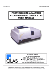
OPERATION AND SAFETY MANUAL Hy-Brid Lifts Models HB-830 Self-Propelled Aerial Work Platform Foreword The purpose of this Operations and Safety Manual is to provide users with the instructions and operating procedures essential to properly and safely operate the Custom Equipment Hy-Brid Lift for its intended purpose, to position personnel and their necessary tools and materials. DANGER THE OPERATION AND SAFETY MANUAL MUST BE READ AND UNDERSTOOD PRIOR TO OPERATING THE MACHINE. THE USER/OPERATOR SHOULD NOT ACCEPT OPERATING RESPONSIBILITY UNTIL THE MANUAL HAS BEEN READ AND UNDERSTOOD AS WELL AS HAVING OPERATED THE LIFT UNDER SUPERVISION OF AN EXPERIENCED AND QUALIFIED OPERATOR. BECAUSE THE MANUFACTURER HAS NO DIRECT CONTROL OVER MACHINE APPLICATION AND OPERATION, PROPER SAFETY PRACTICES ARE THE RESPONSIBILITY OF THE USER AND ALL OPERATING PERSONNEL. WARNING ANY MODIFICATION ON THIS MACHINE WITHOUT THE EXPRESS WRITTEN CONSENT OF THE MANUFACTURER IS PROHIBITED. Fall Protection Notice The guardrail system around the perimeter of the platform is the fall protection system for self-propelled elevating work platforms per the per the American National Standards Institute ANSI/SIA A92.6 Standard. It is prohibited to use an Aerial Work Platform manufactured by Custom Equipment, Inc. with any portion, or all, of the guardrails removed. Lanyard anchorage points on this type of equipment are not required to conform to the applicable standard. However, if anchorage points for lanyard attachments are required by site authorities, or other regulations, the anchorage points on all equipment manufactured by Custom Equipment, Inc. are recommended to be used for work positioning restraints of personnel only. Lanyard lengths are to be determined by operator/owner to restrict the operator to the confines within the guardrail system. WARNING Lanyard Attachment Point USE OF FALL ARREST SYSTEMS ATTACHED TO ANCHORAGE POINTS ON EQUIPMENT MAY CAUSE MACHINE TO TIP, RESULTING IN SERIOUS INJURY OR DEATH. If there is a question on application and/or operation, contact: Custom Equipment, Inc. 2647 Hwy 175 Richfield, WI 53076 USA Phone: 262-644-1300 Fax: 262-644-1320 www.hybridlifts.com Part # SUPO-612 Rev: E Page 2 of 24 Table of Contents Product Description ...................................................................................................................................... 4 Purpose ..................................................................................................................................................... 4 Machine Specifications ............................................................................................................................. 5 Safety ............................................................................................................................................................ 6 Safety Symbols .......................................................................................................................................... 6 General Rules and Precautions ................................................................................................................. 6 Safety Features & Emergency Controls .................................................................................................... 7 Safety Features ..................................................................................................................................... 7 Safety Indicators & Interlocks ............................................................................................................... 7 Safety Controls ...................................................................................................................................... 8 Maintenance Lock ................................................................................................................................. 9 Safety Guidelines .................................................................................................................................... 12 Transport, Handling, and Storage ............................................................................................................... 13 Preliminary Unpacking Instructions and Dealer Inspection .................................................................... 13 Storage .................................................................................................................................................... 13 Preparation for Transport ....................................................................................................................... 13 Lift/Tie Down Points................................................................................................................................ 14 Center of Mass ........................................................................................................................................ 14 Operation .................................................................................................................................................... 15 Pre-start Inspection................................................................................................................................. 15 Controls ................................................................................................................................................... 15 Sleep Mode ............................................................................................................................................. 15 Controls ...................................................................................................... Error! Bookmark not defined. Upper Control Indicators ........................................................................................................................ 17 Startup .................................................................................................................................................... 19 Shut Down ............................................................................................................................................... 19 Elevating and Lowering ........................................................................................................................... 20 Driving and Steering ................................................................................................................................ 20 Adjusting Maximum Drive Speed ............................................................................................................ 21 Extending the Slide-Out Deck ................................................................................................................. 22 Part # SUPO-612 Rev: E Page 3 of 24 Daily Maintenance ...................................................................................................................................... 22 Charging the Battery ............................................................................................................................... 23 Prestart Inspection Checklist .................................................................................................................. 24 Figure 1: Pothole Guards .............................................................................................................................. 7 Figure 2: Emergency Lowering Cable ............................................................................................................ 8 Figure 3: Maintenance Lock Pin Use ............................................................................................................. 9 Figure 4: Maintenance Lock Pin Storage....................................................................................................... 9 Figure 5: Brake Release ............................................................................................................................... 13 Figure 6: Fork Pockets ................................................................................................................................. 14 Figure 7: Tie-Down Points ........................................................................................................................... 14 Figure 8: Base Controls ............................................................................................................................... 15 Figure 9: Platform Controls ......................................................................................................................... 16 Figure 10: Master Power Switch ................................................................................................................. 19 Figure 11: Slide Brake.................................................................................................................................. 22 Figure 12: Battery Charger LED Display ...................................................................................................... 23 Revision Table: Revision A (07/27/2010): Initial Release Revision E (10/24/2012): Revised logos Product Description Purpose Custom Equipment's Hy-Brid Scissor Lift is an aerial work platform designed to be safe and reliable. The purpose of the machine is to elevate personnel, along with their necessary tools and materials to overhead work locations. Manufacturer approval is required for any use other than the intended use. Part # SUPO-612 Rev: E Page 4 of 24 Machine Specifications (Subject to Change) HB-830 Working Height (maximum) Platform Height (maximum) Stowed Height Ground Clearance (Pothole Guard Stowed) Ground Clearance (Pothole Guard Engaged) Overall Width Overall Length Platform (Retracted, Inside) Slide-Out Deck Length Guard Rail Height Toe Board Height Platform Entrance Step Height Wheel Base Wheel Track Turning Radius (Inside) Tire Size (Solid, Non-Marking)-Front Tire Size (Solid, Non-Marking)-Rear Lift Capacity (Evenly Distributed): Slide-Out Deck Capacity Horizontal/Manual Force Machine Weight (Unloaded) (Approx.) Minimum Wheel Load-Contact Pressure Maximum Wheel Load-Contact Pressure Unloaded Machine Loading-Floor Pressure Loaded Machine Loading-Floor Pressure 14 ft. 8 ft. 69.25 in. 2 in. 0.375 in. 30 in. 47 in. 25 in. x 44.5in. 19 in. 43.83 in. 6 in. 26.63 in. 15.74 in. 33.3 in. 23.5 in. Zero 8 in. 10 in. 4.27m 2.44 m 1.76 m 5.1 cm 0. 95cm 0.76 m 1.19 m 0.64 m x 1.13 m 0.48 m 1.1 m 0.15 m 0.68 m 0.4 m 0.85 m 0.60 m Zero 20.3 cm 25.4 cm 500 lbs./1 Person 226.8 kg/1 Person 250 lbs/ 1 Person 113.4 kg/ 1 Person 100 lb. 1100 lb. 69.7 psi 100.9 psi 113.9 PSF 164.9 PSF 445 N 500 kg 480.5 kPa = 4.9 kg/cm2 695.9 kPa = 7.1 kg/cm2 5.45 kPa = 0.06 kg/cm2 7.89 kPa = 0.08 kg/cm2 ENVIRONMENTAL LIMITATIONS Wind Rated Slope Tilt Sensor Activated Gradeability (Stowed Position) Temperature Vibration Sound Drive System (Proportional Electric): Drive Speed (Platform Elevated) Drive Speed (Platform Lowered) Lift/Lower Speed Hydraulic Pressure (max) Hydraulic Fluid Capacity Power System-Voltage Batteries-Deep Cycle Marine Part # SUPO-612 Rev: E No Windy Conditions/Indoor Use Only Level Surface 2° Longitudinal/1.5° Lateral 25% ( 14° Unloaded); 17.5% ( 10° Loaded) -4° F-104° F 8.2 ft/s2 max -20° C-40° C 2.5 m/s2 max 86 dB Normal Use 100 dB Alarms 86 dB Normal Use 100 dB Alarms 0.72 mph 2.3 mph 10/10 sec 1300 psi 1.325 gal 24V DC (2) 12V, Group 27 0.32 m/s 1.0 m/s 10/10 sec 8963 kPa 5.38 L 24V DC (2) 12V, Group 27 Page 5 of 24 Safety Safety Symbols Warnings and instructions that have a direct impact on safety are identified with the following signals: DANGER FAILURE TO FOLLOW THIS WARNING WILL CAUSE DEATH OR PERSONAL INJURY. "DANGER" indicates an imminently hazardous situation, which, if not avoided, will result in death or serious injury. "WARNING" indicates a potentially hazardous WARNING FAILURE TO FOLLOW THIS WARNING MAY CAUSE DEATH OR PERSONAL INJURY. CAUTION FAILURE TO FOLLOW THIS WARNING MAY CAUSE INJURY OR DAMAGE EQUIPMENT situation, which, if not avoided, could result in death or serious injury "CAUTION" indicates a potentially hazardous situation which, if not avoided, could result in minor or moderate injury or damage to equipment General Rules and Precautions Custom Equipment, Inc. designed the Hy-Brid Lift self-propelled scissor lift to be safe and reliable. It is intended for elevating personnel along with their necessary tools and materials to overhead work locations. Vibration does not create significant hazards on this machine. An operator of any type of work platform is subject to certain hazards that cannot be protected by mechanical means. It is therefore essential that operators be competent, careful, physically and mentally fit and thoroughly trained in safe operation of this machine. Although Custom Equipment, Inc. conforms to specified ANSI & OSHA, it is the responsibility of the owner to instruct operators with the safety requirements made not only by Custom Equipment, Inc., but by the various safety boards in your area, as well as additional requirements set forth by ANSI & OSHA If you come across a situation that you think might be unsafe, stop the platform and request further information from qualified sources before proceeding. WARNING NEVER REACH BETWEEN SCISSORS LINKS OR PROP UP PLATFORM. CAUTION STEERING BRACKETS EXTENDING BEYOND THE SIDES OF THE BASE MAY OCCUR IN TIGHT TURNING SITUATIONS TIGHT TURNING WARNING – Potential damage to walls, etc., may occur in tight turning situations due to the steering brackets extending beyond the sides of the base. Part # SUPO-612 Rev: E Page 6 of 24 Safety Features & Emergency Controls Safety Features Puncture-proof Wheels. Guardrails - 43.83 in. height with 6 in. kick plates. Non-slip Deck. Entrance Gate. Automatic Parking Brake. Free Descent Protection. A velocity fuse is installed in the hydraulic circuit to prevent the platform from descending in case of a ruptured hydraulic hose. The platform is hydraulically locked until hose has been replaced. Decals. Danger, Caution, and Warning decals are displayed at various locations on this unit. Key Switch Security. A key switch is required to prevent unauthorized use. Safety Indicators & Interlocks Tilt Alarm An audible alarm sounds when the machine is tilted more than 2° longitudinally or 1.5° laterally. Lower the platform and move to a level surface. For some models, all functions except lowering may be disabled. For models with this safety feature, if the unit is not in the stowed position and tilted, drive, steer, and lifting operations are inhibited. Lower the machine and move to a level surface. Descent/Motion Alarm An audible alarm sounds when the machine is lowering. Some models also sound an alarm when the machine is elevating or driving. Pothole Protection Pothole guards are required to be in place when the lift is in the elevated position. If the guards are blocked or not functioning properly, elevating functions will be inhibited. Lower the machine and do not operate until the problem is repaired or the obstruction is removed. Figure 1: Pothole Guards Part # SUPO-612 Rev: E Page 7 of 24 Safety Controls Descent--Manual Override For manually lowering the scissors, a manual down valve on the cylinder is provided. To lower the scissors, pull the cable located near the rear of the machine. Emergency Down Cable Figure 2: Emergency Lowering Cable WARNING IF PLATFORM SHOULD FAIL TO LOWER, DO NOT ATTEMPT TO CLIMB DOWN THE BEAM ASSEMBLY. SERIOUS INJURY MAY RESULT. HAVE AN EXPERIENCED OPERATOR USE THE EMERGENCY LOWERING PROCEDURE TO SAFELY LOWER THE PLATFORM. WARNING BEFORE LOWERING PLATFORM, RETRACT THE DECK EXTENSION. Emergency Stop This lift is equipped with two emergency stop switches, one at the platform control and one at the base control, that when activated, will render the unit inoperable until reset. To reset, pull the button out. If the unit is powered down without turning off the joystick (i.e. using the emergency stop), there will be an error when powering up again. (Communication Error—9 Flashes). To clear, with the machine on, turn the joystick off and back on. WARNING PUSHING THE EMERGENCY STOP BUTTON WILL APPLY BRAKES IMMEDIATELY. THIS MAY CAUSE UNEXPECTED PLATFORM MOVEMENT AS THE MACHINE COMES TO A SUDDEN STOP. BRACE YOURSELF AND SECURE OBJECTS ON THE PLATFORM DURING OPERATION OF THE MACHINE. Part # SUPO-612 Rev: E Page 8 of 24 Maintenance Lock The maintenance lock pins must be placed into position whenever the machine is being serviced in the raised or partially raised position. Serious injury and/or death could result if maintenance lock is not used properly. Maintenance Pin Location When in Use Figure 3: Maintenance Lock Pin Use Pin Storage Location Figure 4: Maintenance Lock Pin Storage Part # SUPO-612 Rev: E Page 9 of 24 Safety and Control Decals Part # SUPO-612 Rev: E Page 10 of 24 PART # DECAL MEANING OR DESIGNATION QTY. DE600-01 WARNINGS 1 DE600-03B MAX CAPACITY 500 LB/226.8 KG 3 DE600-04 PLATFORM EXTENSION MUST BE LOCKED IN PLACE AT ALL TIMES. ENTRANCE GATE MUST BE CLOSED BEFORE OPERATING PLATFORM. FAILURE TO FOLLOW INSTRUCTIONS COULD CAUSE DEATH, PERSONAL INJURY, AND PROPERTY DAMAGE. 1 DE600-08 BATTERIES PRODUCE EXPLOSIVE GAS. CHARGE BATTERIES IN WELL VENTILATED AREA. DO NOT EXPOSE TO SPARKS OR FLAMES. 1 DE600-09 ELECTROCUTION HAZARD INJURY OR DEATH WILL RESULT FROM CONTACT WOTH MACHINE IF IT BECOMES ELECTRICALLY CHARGED. 2 DE600-16C KEEP CLEAR DECAL (KEEP) 2 DE600-16D KEEP CLEAR DECAL (CLEAR) 2 DE600-17 SAFETY STRIPE (LENGTH VARIES) 4 DE600-21 BRAKE RELEASE DECAL 1 DE600-22 RELEASE BRAKE WHEN WINCHING OR PUSHING. DO NOT TOW. 1 DE600-02 DE600E-02 DANGERS (DE600E-02 USED ON C MODELS) 1 DE600E-05 DANGER—TIP OVER HAZARD: IF TILT ALARM SOUNDS, MACHINE IS ON A SLOPE. LOWER PLATFORM AND MOVE TO A LEVEL SURFACE. 1 DE600E-06 REPLACE TIRES WITH MANUFACTURER’S EQUIPMENT ONLY. FAILURE TO USE MANUFACTURER’S TIRES MAY CAUSE INSTABILITY. REFER TO MAINTENANCE MANUAL FOR REPLACEMENT PART NUMBER. 2 DE600E-10 IMPROPER USE HAZARD FAILURE TO READ, UNDERSTAND AND OBEY THE ENCLOSED SAFETY MAY RESULT IN DEATH OR SERIOUS INJURY. 1 DE600E-14 MAINTENANCE LOCK PIN DECAL--DANGER DO NOT ENTER THE SPACE BENEATH THE WORK PLATFORM OR SCISSORS STRUCTURE DURING MAINTENANCE UNLESS MAINTENANCE LOCK IS IN PLACE. 3 DE600E-18 REPLACEMENT BATTERY MUST WEIGH A MINIMUM OF 47 POUNDS/21.4 KG. FAILURE TO MEET MINIMUM WEIGHT REQUIREMENT MAY CAUSE MACHINE INSTABILITY. 2 DE600E-20 CRUSHING HAZARD DECAL 3 DE600E-29 FOR EMERGENCY LOWERING, PULL CABLE 1 DE603-2 HB-830 MODEL NUMBER DECAL 2 DE610 LOWER CUSTOM EQUIPMENT LOGO 2 DE613 LANYARD ATTACHMENT POINT DECAL 1 DE626 PH WARNING DECAL 2 DE619 CHARGER CORD INPUT 110V AC 1 DE633 LOWER CONTROLS 1 DE639 UPPER CONTROLS 1 DE648 THIS MACHINE IS EQUIPPED WITH A POWER-SAVING SLEEP TIMER. AFTER TWO HOURS OF NO DRIVE, ELEVATE, OR LOWER FUNCTION, THE MACHINE WILL AUTOMATICALLY SHUT DOWN. TO RESET, SWITCH POWER OFF AND BACK ON. 1 DE7005 SERIAL NUMBER PLATE 1 NO PT# SMALL SERIAL NUMBER REFERENCE 1 Part # SUPO-612 Rev: E Page 11 of 24 Safety Guidelines Only qualified operators may operate this unit. All operators must read and understand the Operation and Safety Manual. They must understand all decals and warning labels on unit. Do not work on platform if your physical condition is such that you feel dizzy or unsteady in any way. Do not neglect/misuse machine. Report any misuse of equipment to proper personnel. Prevent unauthorized use; when unit is not in use, remove key. It is recommended all personnel on unit wear approved personal protective equipment (PPE), i.e. head gear. Use machine only for purposes for which it was intended. Lift should never be used as a crane. Do not exceed the load capabilities of the platform. Distribute load evenly over platform floor area. Never use unit as electrical grounds for arc welding. Do not override any hydraulic, mechanical, or electrical safety devices. Check job site for unsafe working conditions. Watch out for others. Keep others clear of operating platform. Never allow others to pass under a raised platform or position the platform over someone. Avoid contact with fixed (buildings, etc.) or moving (vehicles, cranes, etc.) objects. Check work area for overhead obstructions or possible hazards. Follow any applicable national traffic regulations. Use indoors only. Lift is not designed for windy conditions or electrical storms. Unit must be on hard level surface before elevating. Do not operate on incline or uneven surface. You must maintain a clearance between any part of the machine, or its load, and any electrical line or apparatus. Follow local power line clearance regulations. DANGER DO NOT OPERATE MACHINE NEAR POWER LINES. THE PLATFORM AND ENCLOSURES ARE NOT INSULATED. Equipment is only as safe as the operator. Do not use ladders or scaffolding on the platform to obtain greater height. Do not enter or exit platform while machine is in motion. Never mount or dismount a raised platform. Make sure entry gate is secured before operating machine from the platform. Never belt or tie off to an adjacent structure. Secure tools and materials. Personnel must maintain a firm footing on the platform floor and work only within the platform area. It is recommended to avoid sudden braking or steering. Go slowly and leave more maneuvering room during cold weather operation Before operation, ensure that the machine is properly serviced. Do not use machine if it is not working properly. Make sure platform rails and pins are secured. Operator shall use the maintenance lock when performing all types of maintenance procedures. Part # SUPO-612 Rev: E Page 12 of 24 Do not smoke while charging the battery. Do not touch electrical connection points. Contamination or damage due to electrostatic discharge could result. Transport, Handling, and Storage Preliminary Unpacking Instructions and Dealer Inspection Maintenance locks must be engaged prior to inspecting or servicing the unit when the platform is elevated. Inspect machine for any possible damage during shipment; perform a pre-delivery inspection. See checklist in the Maintenance Manual. Reset emergency stop switches, if necessary. Storage After periods of storage, exposure to extremes of ambient conditions-heat, cold, moisture, dust etc. inspect the machine. Refer to the Pre-Delivery/ Frequent Inspection Checklist in the Maintenance Manual. Preparation for Transport Lower the work platform to the down position. Bring the platform slide-out extension into the retracted position and lock in place. Turn key switch to off position. Check entire machine for loose or unsecured items. Remove any loose items from machine. The machine can be pushed by releasing the parking brake at the rear of the machine. Push both levers toward the floor. To resume normal operation, make sure both levers are up. Do not attempt to push or tow unit with the brakes applied. Severe gear damage will occur. Towing is not recommended. NOTE: The drive system will not function if the parking brake is in the released position. To release brake for winching or pushing, rotate brake handles. Do not push at speeds more than 2 mph (0.9 m/s). Figure 5: Brake Release Part # SUPO-612 Rev: E Page 13 of 24 Lift/Tie Down Points Fork lift pockets are provided from the front and back of the unit for loading and unloading. A forklift from the side of the machine is not recommended. Do not use a forklift underneath the machine from the back. When moving machine with a forklift, do not let machine slide along floor. Bring forklift to a stop and then gently lower the machine. Fork Pockets Figure 6: Fork Pockets Tie down points are provided for securing the machine on a trailer or truck bed for transport between places of use. They may also be used as lift points. Tie-Down/Lift Figure 7: Tie-Down Points WARNING DO NOT OVER-TIGHTEN LOAD BINDERS WHEN SECURING LOAD FOR TRANSPORT Center of Mass Part # SUPO-612 Rev: E Page 14 of 24 HB830: x=25 in. y=18 in. Operation Pre-start Inspection Before use each day or at the beginning of each shift, the machine shall be given a visual inspection and functional test. Repairs (if any) must be made prior to operating the machine, as it is critical to ensure safe operation of the machine. A checklist for pre-start inspection can be found in the Daily Maintenance section of this manual. Controls Sleep Mode After two hours, if there is no driving, elevating, or lowering, the controls will go into Sleep Mode. The machine will shut down, and all indicator lights will be off. To reset sleep mode, turn the power off for a few seconds and back on. Item 1 2 3 Figure 8: Base Controls Part # SUPO-612 Rev: E Base Controls Control/Indicator Up/Down Rocker Switch (Operation described as follows) Beeper Alarm- Tilt (Alarm sounds on for tilt) Beeper Alarm-Motion (Alarm sounds on for descent, and, for some models, motion) 4 Key Switch Power/Selector (Turns power on and off. Operation described as follows) 5 Emergency Stop (Operation described in the Safety Controls section of this manual) 6 Hour Meter (Reads operation hours) Page 15 of 24 Figure 9: Platform Controls Item 1 2 3 4 5 6 7 8 9 10 11 Platform Controls Control/Indicator Emergency Stop (Operation described in the Safety Controls section of this manual) Drive Enable Button (Operation described as follows) Joystick (Operation described as follows) Decrease Speed Button (Operation described as follows) Increase Speed Button (Operation described as follows) On/Off Button (Operation described as follows) Battery Gauge (Displays battery charge as described below) Speedometer (Displays relative speed as described below) Service Indicator (Displays diagnostic codes. See Maintenance Manual) Lift/Lower Enable (Operation described below) Up/Down Rocker Switch (Operation described below) Part # SUPO-612 Rev: E Page 16 of 24 Upper Control Indicators Display Description All LEDs OFF Meaning Power is OFF LEDs ON steady Power is ON. Battery charge is displayed. Any green LEDs lit indicate well charged batteries. If only amber and red LEDs are lit, the batteries are moderately charged. If only red LEDs are lit, the batteries are running out of charge. Recharge as soon as possible. Left red LED flashing Battery charge is low. Recharge as soon as possible. Right to Left ‘chase’ This feature is not used on this model. Left to Right ‘chase’ alternating with steady display All LEDs flashing slowly Drive is not enabled. Joystick control is on programming, inhibit and/or charging mode. 2 flashing Amber LEDs Communication fault between joystick controls and power module. Check that battery is charged, and check cable connections and control module for damage. Out of Neutral At Power Up (OONAPU) condition. Release the joystick back to neutral. The amber Service Indicator LED displays diagnostic codes. 9 Flashes indicates a Communication Error. One cause of this error is when the unit is powered down without turning off the joystick (i.e. using the emergency stop). To clear, with the machine on, turn the joystick off and back on. Part # SUPO-612 Rev: E Page 17 of 24 See Service Manual for additional flash codes. Part # SUPO-612 Rev: E Page 18 of 24 Startup DANGER 1. 2. 3. 4. 5. THE OPERATOR MUST BE AWARE OF THE ENVIRONMENT. DO NOT RAISE THE PLATFORM IF THE MACHINE IS NOT ON A FIRM, LEVEL SURFACE. Check that the work area is safe. Machine must be on a hard, level, surface before operation. Move the key in the lower control panel is in the "ON" position for the chassis or platform control. The key can be removed from either position to prevent unauthorized operation. Enter the work platform in the stowed position using the constant three point contact method. Press the on/off button on the platform controls. All battery gauge indicators will light briefly. Then the current battery charge will be indicated. Follow all general rules and precautions stated in this manual Figure 10: Master Power Switch Shut Down 1. 2. 3. 4. 5. 6. When finished with the machine, place the platform in the stowed position. Park the machine on a level surface. Press the on/off button on the platform controls. All LEDs will turn off. Carefully exit the platform using the constant three point contact method. NEVER JUMP OFF PLATFORM. Remove key from lower control panel to prevent unauthorized use. Charge batteries after use. Part # SUPO-612 Rev: E Page 19 of 24 Elevating and Lowering Using Lower Base Controls Make sure the base controls are selected with the selector switch at the base controls. Press the Lift/Lower Switch to raise or lower the platform. Pressing the top of the switch raises the platform, pressing the bottom lowers the platform. Using Upper Platform Controls Make sure the platform controls are selected with the key switch selector at the base controls. To raise or lower the platform, press the Lift/Lower Enable Button in front of the joystick. While holding down the Enable Button, hold down the Up or Down Button until the platform is in the desired position. Driving and Steering Braking: For parking, the brake is automatically applied when the joystick is positioned in the center (neutral) position. In the event of a machine failure, the machine can be pushed by releasing the parking brake at the rear of the machine. See the “Preparation for Transport” section in this manual for brake release information. WARNING CHECK THAT THE ROUTE OF TRAVEL TO BE TAKEN IS CLEAR OF PEOPLE, OBSTRUCTIONS, DEBRIS, HOLES, AND DROP OFFS, AND IS CAPABLE OF SUPPORTING THE MACHINE. WARNING IF THE VEHICLE DRIVES WITHOUT DEMAND, PRESS THE POWER BUTTON OR THE EMERGENCY STOP. SEE THE SAFETY CONTROLS SECTION OF THIS MANUAL. THE CONTROLLER COULD CAUSE THE VEHICLE TO COME TO A SUDDEN STOP. BRACE YOURSELF AND SECURE OBJECTS ON THE PLATFORM DURING OPERATION OF THE MACHINE. Check front steer wheel direction before driving. If there is resistance in turning the casters while pivoting machine, steer forward to allow casters to straighten out before turning. For best control, distribute the load the work platform toward rear of machine if possible. To drive, hold down the drive enable button while moving the joystick. Moving the joystick will cause the machine to drive in that direction. Moving the joystick handle away from the operator will cause FORWARD travel and pulling the joystick toward the operator will cause REVERSE travel. Moving the Part # SUPO-612 Rev: E Page 20 of 24 joystick directly to one side or the other will cause the machine to pivot. Travel speed is proportional and is controlled by the joystick. The farther it is moved, the faster the speed will be. The joystick returns to the neutral position when released. WARNING If the vehicle speed surges when going down hill, the common reason is the operation of an over-voltage protective device to prevent the risk of battery damage or explosion due to energy generation if batteries are already charged. To prevent surging with fully charged batteries, descend hills slowly. Adjusting Maximum Drive Speed The speedometer is used to gauge the relative speed of the machine in comparison to the maximum speed. The right-most LED indicates current maximum speed, which can be adjusted. A single green LED on the left will flash when the platform is elevated, indicating that the unit is in reduced speed mode. The user can adjust the machine’s top drive speed to suit the environment. The currently selected top speed is shown on the Speedometer and can be adjusted using the Increase Speed (Hare) and Decrease Speed (Tortoise) buttons. Each of the six large LEDs on the speedometer represent approximately 0%, 20%, 40%, 60%, 80%, and 100% of the machine’s maximum top speed. There are two styles of top speed adjustment: “5 Speed” and “VSP” Mode. The user can toggle between the modes by holding down both the Increase Speed and Decrease Speed Buttons for approximately 2 seconds. The joystick will beep when the mode has been changed. VSP can be disabled In “5 Speed” mode, pressing the Increase or Decrease Speed buttons steps between one of the 5 top speeds 20% to 100%. In VSP mode a single press of the Increase or Decrease Speed buttons steps between one of the 5 top speeds 20% to 100%. Pressing and holding the Increase or Decrease Button ramps the top speed up or down in fine steps. Part # SUPO-612 Rev: E Page 21 of 24 Extending the Slide-Out Deck Stand on the platform deck. Grip the Slide Lock Handle to allow the deck to slide. Slide the deck out to the locking point at approximately 13 in. extension. Release the handle to keep deck in place. Be sure lock is engaged before entering. Figure 11: Slide Brake WARNING DO NOT EXCEED THE RATED CAPACITY. THE CAPACITY OF THE SLIDE OUT DECK IS MAXIMUM 250 LBS. OR ONE PERSON. WARNING IF THE SLIDE-OUT DECK IS EXTENDED, CHECK FOR CLEARANCE UNDER AREA BEFORE LOWERING PLATFORM. WARNING DO NOT DRIVE UNIT WHEN STANDING ON DECK. STAND ON PLATFORM BEHIND JOYSTICK. Daily Maintenance CAUTION FAILURE TO PERFORM INSPECTIONS AND PREVENTITIVE MAINTENANCE AT RECOMMENDED INTERVALS MAY RESULT IN THE UNIT BEING OPERATED WITH A DEFECT THAT MAY RESULT IN INJURY OR DEATH OF THE OPERATOR. Regular inspection and conscientious maintenance is important to efficient economical operation of this machine. It will help to assure that equipment will perform satisfactorily with a minimum or service and repair. Make checks at the stated intervals or more frequently if required by local operating conditions. A Pre-Start Inspection Checklist is included in this manual. In addition, Pre-Delivery/Frequent and Monthly Checklists are included in a separate Maintenance Manual. Also refer to the Maintenance Manual for replacement part information. Part # SUPO-612 Rev: E Page 22 of 24 Charging the Battery This unit is equipped with deep cycle 12-volt batteries. The care and maintenance of your battery has much to do with how well this unit functions. Battery wiring and water level should be checked monthly. Do not overfill. When the cells are too full, fluid will seep out when charging. Note: The surrounding temperature greatly affects the power reserve within a battery. Example: A battery that is 100% charged at 80° F (27°C) drops to 65% at 32°F (0°C) At 0°F (-18°C), this battery will drop to 40% efficiency. WARNING LEAD-ACID BATTERIES GENERATE EXPLOSIVE GASES. KEEP SPARKS AND FLAME AWAY FROM BATTERIES. DO NOT SMOKE WHILE CHARGING. Park the machine on a level surface. Plug charger into AC outlet until charged. Unplug charger. The charger will not begin the charging cycle on severely discharged batteries. This will be evident by the indicators blinking simultaneously. Figure 12: Battery Charger LED Display 50% 75% 100% GEL Charger LED Display Charging State 0 to 50% charged Blinking Off Off NA 50% to 75% charged On Blinking Off NA 75% to 100% charged On On Blinking NA 100% charged On On On NA Charge for flooded type batteries NA NA NA Off Charge for Sealed type batteries NA NA NA On Abnormal Cycle Off Off Blinking NA WARNING DO NOT OPERATE UNIT WHILE CHARGING. Part # SUPO-612 Rev: E CAUTION NEVER ADD ACID TO BATTERY! Page 23 of 24 Prestart Inspection Checklist WARNING THIS CHECKLIST MUST BE USED AT THE BEGINNING OF EACH SHIFT OR AFTER EVERY SIX TO EIGHT HOURS OF USE. FAILURE TO DO SO COULD AFFECT THE SAFETY OF THE OPERATOR. MODEL HB-830 SERIAL NUMBER ______________ 1. 2. 3. Keep inspection records up-to-date. Record and report all discrepancies to your supervisor. A dirty machine cannot be properly inspected. Y-Yes/Acceptable N-No/Unacceptable R-Repaired Y Description N Visual Inspections Check that there are no damaged, dented, or bent structural members. There are no loose or missing parts. Check that warning and instructional labels are legible and secure. Ensure that load capacity is clearly marked. Check the platform rails and safety gate for damage. Platform and base controls are not missing, damaged, or disconnected. Electrical cables and wires are not torn, frayed, or disconnected. Hydraulic hoses are not torn or loose, and there are no leaks. Check that hoses and the cables have no worn areas or chafing. Check the hydraulic fluid level with the platform fully lowered. Check the tires for damage. Check that wheel axle retaining rings and set screw in rear wheel are tight. Check that all snap rings are secure in grooves on pivot pins. Functional Tests Gate closes automatically and latches (alignment can be adjusted with screw on toe board or railing if necessary). Platform Controls: Check all switches and push buttons for proper operation. Emergency Stop (Stops all movement) Drive Enable (Must be activated to drive) Joystick (Return to neutral, drives forward, reverse, left, right) Lift Enable (Must be activated to elevate) Rocker Switch (Elevates, Lowers) Base Controls: Check all switches and push buttons for proper operation. Emergency Stop (Stops all movement) Key Switch (Selects Platform Control, Ground Control, or Off) Up/Down Rocker Switch (Elevates, Lowers) Hour meter (Displays Drive Hours) Alarms (Not damaged, sounds for descent) Wheels: Front and rear wheels rotate, pivot freely. Drives in slow speed when elevated. Brakes: Machine stops when joystick released. Pothole guards deploy and lock when platform is raised. Lift does not elevate when pothole guards are blocked. DATE _______________ Part # SUPO-612 Rev: E INSPECTED BY ____________________________ Page 24 of 24 R