1
Logix5000™
Controllers Motion
Instructions
1756 ControlLogix®,
1768 CompactLogix™,
1789 SoftLogix™,
20D PoweFlex®700S with
DriveLogix™
Reference Manual
Important User Information
Solid state equipment has operational characteristics differing from those of
electromechanical equipment. Safety Guidelines for the Application,
Installation and Maintenance of Solid State Controls (Publication SGI-1.1
available from your local Rockwell Automation sales office or online at
http://www.ab.com/manuals/gi) describes some important differences
between solid state equipment and hard-wired electromechanical devices.
Because of this difference, and also because of the wide variety of uses for
solid state equipment, all persons responsible for applying this equipment
must satisfy themselves that each intended application of this equipment is
acceptable.
In no event will Rockwell Automation, Inc. be responsible or liable for
indirect or consequential damages resulting from the use or application of
this equipment.
The examples and diagrams in this manual are included solely for illustrative
purposes. Because of the many variables and requirements associated with
any particular installation, Rockwell Automation, Inc. cannot assume
responsibility or liability for actual use based on the examples and diagrams.
No patent liability is assumed by Rockwell Automation, Inc. with respect to
use of information, circuits, equipment, or software described in this manual.
Reproduction of the contents of this manual, in whole or in part, without
written permission of Rockwell Automation, Inc. is prohibited.
Throughout this manual, when necessary we use notes to make you aware of
safety considerations.
WARNING
IMPORTANT
ATTENTION
Identifies information about practices or circumstances
that can cause an explosion in a hazardous environment,
which may lead to personal injury or death, property
damage, or economic loss.
Identifies information that is critical for successful
application and understanding of the product.
Identifies information about practices or circumstances
that can lead to personal injury or death, property
damage, or economic loss. Attentions help you:
• identify a hazard
• avoid a hazard
• recognize the consequence
SHOCK HAZARD
Labels may be located on or inside the equipment (e.g.,
drive or motor) to alert people that dangerous voltage may
be present.
BURN HAZARD
Labels may be located on or inside the equipment (e.g.,
drive or motor) to alert people that surfaces may be
dangerous temperatures.
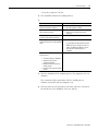
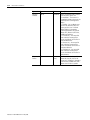
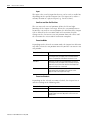
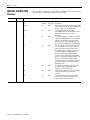
Summary of Changes
Introduction
This release of this document contains new and updated information.
To find new and updated information, look for change bars, as shown
next to this paragraph.
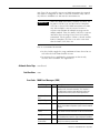
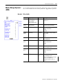
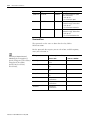
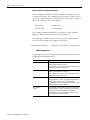
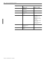
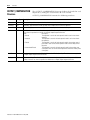
Updated Information
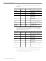
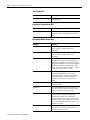
This document contains the following changes:
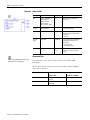
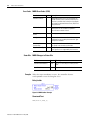
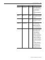
Change
Page
Error code 65—The position of the axis overflowed before you started
this move.
1-10, 3-37, 3-91, 7-32,
7-70
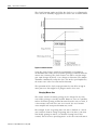
Using Different Termination Types When Blending Instructions
7-3
Choose a termination type
7-9
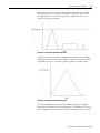
How do I get a triangular velocity profile?
7-11
Blending Moves at Different Speeds
7-12
New Termination Types
7-13, 7-14, 7-38, 7-38
Attention: If you use an S-Curve profile
3-5, 3-18, 3-28, 3-54,
7-15, 7-39, 7-81, 7-90
InhibitStatus bit
A-10, A-19
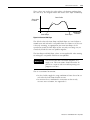
The axis could overshoot its target position if you reduce the
deceleration while a move is in process.
1
3-51, 3-51, 7-89
Publication 1756-RM007G-EN-P - May 2005
Summary of Changes
2
Notes:
Publication 1756-RM007G-EN-P - May 2005
Preface
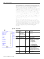
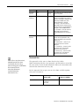
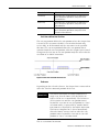
Introduction
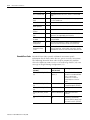
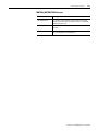
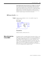
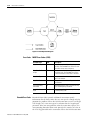
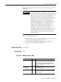
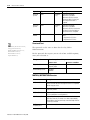
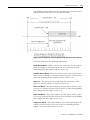
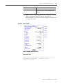
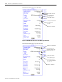
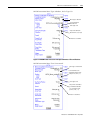
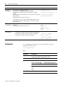
This manual is one of several Logix5000-based instruction manuals.
Task/Goal:
Documents:
Program the controller for sequential
applications
Logix5000 Controllers General Instructions Reference Manual, publication
1756-RM003
Program the controller for process or drives
applications
Logix5000 Controllers Process Control and Drives Instructions Reference Manual,
publication 1756-RM006
Program the controller for motion
applications
Logix5000 Controllers Motion Instructions Reference Manual, publication
1756-RM007
You are here
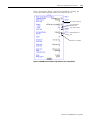
Program the controller to use equipment
phases
PhaseManager User Manual, publication LOGIX-UM001
Import a text file or tags into a project
Logix5000 Controllers Import/Export Reference Manual, publication 1756-RM084
Export a project or tags to a text file
Convert a PLC-5 or SLC 500 application to a
Logix5000 application
Logix5550 Controller Converting PLC-5 or SLC 500 Logic to Logix5550 Logic Reference
Manual, publication 1756-6.8.5
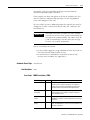
You can use these Logix5000 controllers for motion control:
•
•
•
•
1756 ControlLogix® controllers
1768 CompactLogix™ controllers (available in the future)
1789 SoftLogix5800™ controllers
20D PoweFlex®700S with DriveLogix™ controllers
If you have a PoweFlex®700S with DriveLogix™ controller
You can’t use these instructions with a DriveLogix controller:
•
•
•
•
•
•
1
Motion
Motion
Motion
Motion
Motion
Motion
Direct Drive On (MDO)
Direct Drive Off (MDF)
Apply Axis Tuning (MAAT)
Run Axis Tuning (MRAT)
Apply Hookup Diagnostics (MAHD)
Run Hookup Diagnostics (MRHD)
Publication 1756-RM007G-EN-P - May 2005
Preface
2
Who Should Use This
Manual
This document provides a programmer with details about the motion
instructions that are available for a Logix5000 controller. You should
already be familiar with how the Logix5000 controller stores and
processes data.
Novice programmers should read all the details about an instruction
before using the instruction. Experienced programmers can refer to
the instruction information to verify details.
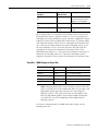
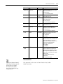
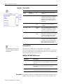
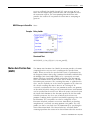
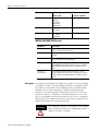
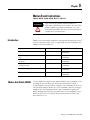
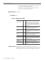
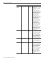
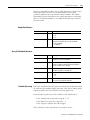
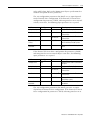
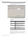
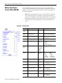
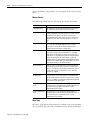
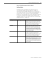
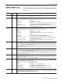
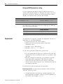
Purpose of This Manual
This manual provides information about each motion instruction.
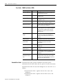
This section:
Provides this type of information:
Instruction name
Identifies the instruction.
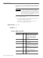
Defines whether the instruction is an input or an output instruction.
Operands
Lists all the operands of the instruction.
Structured Text
Describes the use of operands in Structured Text format.
Motion Instruction structure Lists control status bits and values, if any, of the instruction.
Description
Describes the instruction’s use.
Defines any differences when the instruction is enabled and disabled, if
appropriate.
Arithmetic status flags
Defines whether or not the instruction affects arithmetic status flags.
Fault conditions
Defines whether or not the instruction generates minor or major faults.
if so, defines the fault type and code.
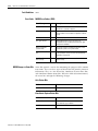
Error Codes
Lists and defines the applicable error codes.
Status Bits
Lists affected status bits, their states, and definitions.
Example
Provides at least one programming example.
Includes a description explaining each example.
Publication 1756-RM007G-EN-P - May 2005
Preface
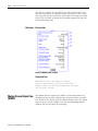
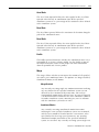
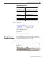
Sequential Function Chart
(SFC)
3
A Sequential Function Chart is a flowchart that controls your machine
or process. SFC uses steps and transitions to perform specific
operations or actions. You can use SFC to:
• Organize the functional specification of your system.
• Program and control your system as a series of steps and
transitions.
You gain the following advantages by using Sequential Function Chart
(SFC).
•
•
•
•
•
•
Graphical division of processes into major logic pieces.
Faster repeated execution of individual pieces of your logic.
A more simple screen display.
Time to design and debug your program is reduced.
Troubleshooting is faster and easier.
Direct access to the point in the logic where the machine
faulted.
• Easier to enhance and update.
For more detailed information about how to program and use SFC,
see Logix5000 Controllers Common Procedures Manual, publication
1756-PM001.
Publication 1756-RM007G-EN-P - May 2005
Preface
4
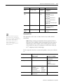
Conventions and Related
Terms
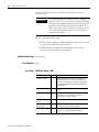
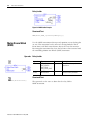
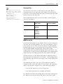
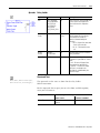
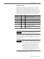
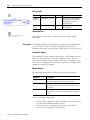
Set and clear
This manual uses set and clear to define the status of bits (booleans)
and values (non-booleans):
This term:
Means:
set
the bit is set to 1 (ON)
a value is set to any non-zero number
clear
the bit is cleared to 0 (OFF)
all the bits in a value are cleared to 0
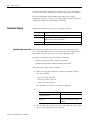
An instruction executes faster and requires less memory if all the
operands of the instruction use the same optimal data type, typically
DINT or REAL.
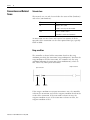
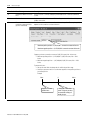
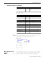
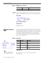
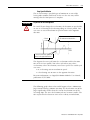
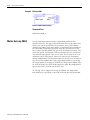
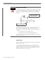
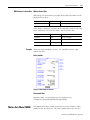
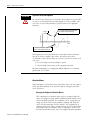
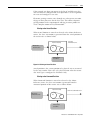
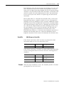
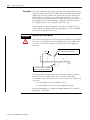
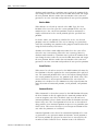
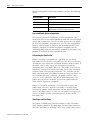
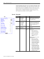
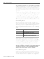
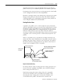
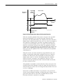
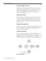
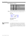
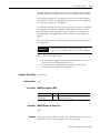
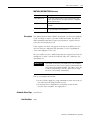
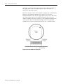
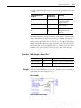
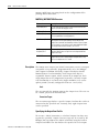
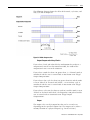
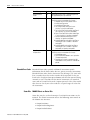
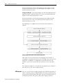
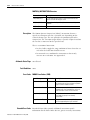
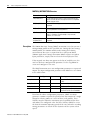
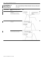
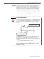
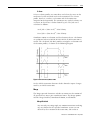
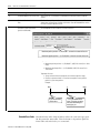
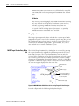
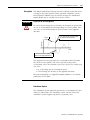
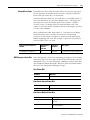
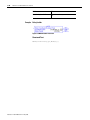
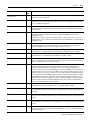
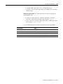
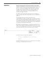
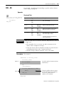
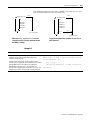
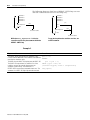
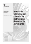
Rung condition
The controller evaluates ladder instructions based on the rung
condition preceding the instruction (rung-condition-in). Based on the
rung-condition-in and the instruction, the controller sets the rung
condition following the instruction (rung-condition-out), which in
turn, affects any subsequent instruction.
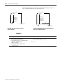
input instruction
rung-in
condition
output instruction
rung-out
condition
If the rung-in condition to an input instruction is true, the controller
evaluates the instruction and sets the rung-out condition based on the
results of the instruction. If the instruction evaluates to true, the
rung-out condition is true; if the instruction evaluates to false, the
rung-out condition is false.
Publication 1756-RM007G-EN-P - May 2005
Table of Contents
Chapter 1
Motion Concepts
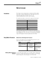
Introduction . . . . . . . . . . . . . . . . . . . . . . . . . .
Using Motion Parameters. . . . . . . . . . . . . . . . .
Modifying Motion Configuration Parameters
Instruction Timing. . . . . . . . . . . . . . . . . . . . . .
Immediate Type Instructions . . . . . . . . . . .
Message Type Instructions . . . . . . . . . . . . .
Process Type Instructions . . . . . . . . . . . . . .
Using the Motion Instruction Structure . . . . . . .
Motion Instruction Structure . . . . . . . . . . . .
Error codes (.ERR) . . . . . . . . . . . . . . . . . .
Message Status (.STATUS) . . . . . . . . . . . . .
Execution Status (.STATE) . . . . . . . . . . . . .
Profile Segment (.SEGMENT) . . . . . . . . . . .
.
.
.
.
.
.
.
.
.
.
.
.
.
.
.
.
.
.
.
.
.
.
.
.
.
.
.
.
.
.
.
.
.
.
.
.
.
.
.
.
.
.
.
.
.
.
.
.
.
.
.
.
.
.
.
.
.
.
.
.
.
.
.
.
.
.
.
.
.
.
.
.
.
.
.
.
.
.
.
.
.
.
.
.
.
.
.
.
.
.
.
.
.
.
.
.
.
.
.
.
.
.
.
.
.
.
.
.
.
.
.
.
.
.
.
.
.
1-1
1-1
1-1
1-2
1-2
1-3
1-4
1-7
1-7
1-8
1-11
1-11
1-11
.
.
.
.
.
.
.
.
.
.
.
.
.
.
.
.
.
.
.
.
.
.
.
.
.
.
.
.
.
.
.
.
.
.
.
.
.
.
.
.
.
.
.
.
.
.
.
.
.
.
.
.
.
.
.
.
.
.
.
.
.
.
.
.
.
.
.
.
.
.
.
.
.
.
.
.
.
.
.
.
.
.
.
.
.
.
.
.
.
.
.
.
.
.
.
.
.
.
.
.
.
.
.
.
.
.
.
.
.
.
.
.
.
.
.
.
.
.
.
.
.
.
.
.
.
.
.
.
.
.
.
.
.
.
.
.
.
.
.
.
.
.
.
.
.
.
.
.
.
.
.
.
.
.
.
.
.
.
.
.
.
.
.
.
.
.
.
.
.
.
.
.
.
.
.
.
.
.
.
.
.
.
.
.
.
.
.
.
.
.
.
.
.
.
.
.
.
.
.
.
.
.
.
.
.
.
.
.
.
.
.
.
.
.
.
.
.
.
.
.
.
.
.
.
.
.
.
.
.
.
.
.
.
.
.
.
.
.
.
.
.
.
.
.
.
.
.
.
.
.
.
.
.
.
.
.
.
.
.
.
.
.
.
.
.
.
.
.
.
.
2-1
2-2
2-3
2-3
2-4
2-4
2-4
2-5
2-5
2-5
2-6
2-6
2-7
2-8
2-8
2-8
2-9
2-9
2-9
2-10
2-10
2-11
2-11
2-12
2-12
2-13
2-13
2-14
2-14
2-15
Chapter 2
Motion State Instructions
1
Introduction . . . . . . . . . . . . . . . . . . .
Motion Servo On (MSO) . . . . . . . . . .
Operands: . . . . . . . . . . . . . . . . . .
Description:. . . . . . . . . . . . . . . . .
Arithmetic Status Flags: . . . . . . . .
Fault Conditions: . . . . . . . . . . . . .
Error Codes: . . . . . . . . . . . . . . . .
Extended Error Codes: . . . . . . . . .
MSO Changes to Status Bits . . . . .
Example: . . . . . . . . . . . . . . . . . . .
Motion Servo Off (MSF). . . . . . . . . . .
Operands: . . . . . . . . . . . . . . . . . .
Description:. . . . . . . . . . . . . . . . .
Arithmetic Status Flags: . . . . . . . .
Fault Conditions: . . . . . . . . . . . . .
Error Codes: . . . . . . . . . . . . . . . .
MSF Changes to Status Bits: . . . . .
Example: . . . . . . . . . . . . . . . . . . .
Motion Axis Shutdown (MASD) . . . . .
Operands: . . . . . . . . . . . . . . . . . .
Description:. . . . . . . . . . . . . . . . .
Arithmetic Status Flags: . . . . . . . .
Fault Conditions: . . . . . . . . . . . . .
Error Codes: . . . . . . . . . . . . . . . .
MASD Changes to Status Bits: . . . .
Example: . . . . . . . . . . . . . . . . . . .
Motion Axis Shutdown Reset (MASR) .
Operands: . . . . . . . . . . . . . . . . . .
Description:. . . . . . . . . . . . . . . . .
Arithmetic Status Flags: . . . . . . . .
.
.
.
.
.
.
.
.
.
.
.
.
.
.
.
.
.
.
.
.
.
.
.
.
.
.
.
.
.
.
.
.
.
.
.
.
.
.
.
.
.
.
.
.
.
.
.
.
.
.
.
.
.
.
.
.
.
.
.
.
.
.
.
.
.
.
.
.
.
.
.
.
.
.
.
.
.
.
.
.
.
.
.
.
.
.
.
.
.
.
.
.
.
.
.
.
.
.
.
.
.
.
.
.
.
.
.
.
.
.
.
.
.
.
.
.
.
.
.
.
.
.
.
.
.
.
.
.
.
.
.
.
.
.
.
.
.
.
.
.
.
.
.
.
.
.
.
.
.
.
.
.
.
.
.
.
.
.
.
.
.
.
.
.
.
.
.
.
.
.
.
.
.
.
.
.
.
.
.
.
.
.
.
.
.
.
.
.
.
.
.
.
.
.
.
.
.
.
.
.
.
.
.
.
.
.
.
.
.
.
Publication 1756-RM007G-EN-P - May 2005
Table of Contents
2
Fault Conditions: . . . . . . . . .
Error Codes: . . . . . . . . . . . . .
Status Bits: . . . . . . . . . . . . . .
Example: . . . . . . . . . . . . . . .
Motion Direct Drive On (MDO) .
Operands: . . . . . . . . . . . . . .
Description: . . . . . . . . . . . . .
Arithmetic Status Flags: . . . . .
Fault Conditions: . . . . . . . . .
Error Codes: . . . . . . . . . . . . .
Extended Error Codes: . . . . .
Status Bits: . . . . . . . . . . . . . .
Example: . . . . . . . . . . . . . . .
Motion Direct Drive Off (MDF). .
Operands: . . . . . . . . . . . . . .
Description: . . . . . . . . . . . . .
Arithmetic Status Flags: . . . . .
Fault Conditions: . . . . . . . . .
Error Codes: . . . . . . . . . . . . .
MDF Changes to Status Bits: .
Example: . . . . . . . . . . . . . . .
Motion Axis Fault Reset (MAFR) .
Operands: . . . . . . . . . . . . . .
Description: . . . . . . . . . . . . .
Arithmetic Status Flags: . . . . .
Fault Conditions: . . . . . . . . .
Error Codes: . . . . . . . . . . . . .
MAFR Changes to Status Bits:
MAFR Example: . . . . . . . . . .
.
.
.
.
.
.
.
.
.
.
.
.
.
.
.
.
.
.
.
.
.
.
.
.
.
.
.
.
.
.
.
.
.
.
.
.
.
.
.
.
.
.
.
.
.
.
.
.
.
.
.
.
.
.
.
.
.
.
.
.
.
.
.
.
.
.
.
.
.
.
.
.
.
.
.
.
.
.
.
.
.
.
.
.
.
.
.
.
.
.
.
.
.
.
.
.
.
.
.
.
.
.
.
.
.
.
.
.
.
.
.
.
.
.
.
.
.
.
.
.
.
.
.
.
.
.
.
.
.
.
.
.
.
.
.
.
.
.
.
.
.
.
.
.
.
.
.
.
.
.
.
.
.
.
.
.
.
.
.
.
.
.
.
.
.
.
.
.
.
.
.
.
.
.
.
.
.
.
.
.
.
.
.
.
.
.
.
.
.
.
.
.
.
.
.
.
.
.
.
.
.
.
.
.
.
.
.
.
.
.
.
.
.
.
.
.
.
.
.
.
.
.
.
.
.
.
.
.
.
.
.
.
.
.
.
.
.
.
.
.
.
.
.
.
.
.
.
.
.
.
.
.
.
.
.
.
.
.
.
.
.
.
.
.
.
.
.
.
.
.
.
.
.
.
.
.
.
.
.
.
.
.
.
.
.
.
.
.
.
.
.
.
.
.
.
.
.
.
.
.
.
.
.
.
.
.
.
.
.
.
.
.
.
.
.
.
.
.
.
.
.
.
.
.
.
.
.
.
.
.
.
.
.
.
.
.
.
.
.
.
.
.
.
.
.
.
.
.
.
.
.
.
.
.
.
.
.
.
.
.
.
.
.
.
.
.
.
.
.
.
.
.
.
.
.
.
.
.
.
.
.
.
.
.
.
.
.
.
.
.
.
.
.
.
.
.
.
.
.
.
.
.
.
.
.
.
.
.
.
.
.
.
.
.
.
.
.
.
.
.
.
.
.
.
.
.
.
.
.
.
.
.
.
.
.
.
.
.
.
.
.
.
.
.
.
.
.
.
.
.
.
.
.
.
.
.
.
.
.
.
.
.
.
.
.
.
.
.
.
.
.
.
.
.
.
.
.
.
.
.
.
.
.
.
.
.
.
.
.
.
.
.
.
.
.
.
.
.
.
.
.
.
.
.
.
.
.
.
.
.
.
.
.
.
.
.
.
.
.
.
.
.
.
.
.
.
.
.
.
.
.
.
.
.
.
.
.
.
.
.
.
.
.
.
.
.
.
.
.
.
.
.
.
.
.
.
.
.
.
.
.
.
.
.
.
.
.
.
.
.
.
.
.
.
.
.
.
.
.
.
.
.
.
.
.
.
.
.
.
.
.
.
.
.
.
.
.
.
.
.
.
.
.
.
.
.
.
.
.
.
.
.
.
.
.
.
.
.
.
.
.
.
.
.
.
.
.
.
.
.
.
.
.
.
.
.
.
.
.
.
.
.
.
.
.
.
.
.
.
.
.
.
.
.
.
.
.
.
.
.
.
.
.
.
.
.
.
.
.
.
.
.
.
.
.
.
.
.
.
.
.
.
.
.
.
.
.
.
.
.
.
.
.
.
.
.
.
.
.
.
.
.
.
.
.
.
.
.
.
.
.
.
.
.
.
.
.
.
.
.
.
.
.
.
.
.
.
.
.
.
.
.
.
.
.
.
.
.
.
.
.
.
.
.
.
.
.
.
.
.
.
.
.
.
.
.
.
.
.
.
.
.
.
.
.
.
.
.
.
.
.
.
.
.
.
.
.
.
.
.
.
.
.
.
.
.
.
.
.
.
.
.
.
.
.
.
.
.
.
.
.
.
.
.
.
.
.
.
.
.
.
.
.
.
.
.
.
.
.
.
.
.
.
.
.
.
.
.
.
.
.
.
.
.
.
.
.
.
.
.
.
.
.
.
.
.
.
.
.
.
.
.
.
.
.
2-15
2-15
2-16
2-16
2-16
2-16
2-17
2-18
2-18
2-18
2-19
2-19
2-19
2-20
2-20
2-20
2-21
2-21
2-21
2-22
2-22
2-22
2-23
2-23
2-24
2-24
2-24
2-25
2-25
Chapter 3
Motion Move Instructions
Publication 1756-RM007G-EN-P - May 2005
Introduction. . . . . . . . . . . . . . .
Motion Axis Stop (MAS) . . . . . .
Operands: . . . . . . . . . . . . .
Description: . . . . . . . . . . . .
Arithmetic Status Flags: . . . .
Fault Conditions: . . . . . . . .
Error Codes: . . . . . . . . . . . .
Extended Error Codes: . . . .
.....................
MAS Changes to Status Bits:
Example: . . . . . . . . . . . . . .
Motion Axis Home (MAH) . . . .
Operands: . . . . . . . . . . . . .
Description: . . . . . . . . . . . .
Arithmetic Status Flags: . . . .
Fault Conditions: . . . . . . . .
.
.
.
.
.
.
.
.
.
.
.
.
.
.
.
.
.
.
.
.
.
.
.
.
.
.
.
.
.
.
3-1
3-2
3-2
3-4
3-7
3-7
3-7
3-7
3-8
3-8
3-8
3-9
3-9
3-9
3-11
3-11
Table of Contents
Error Codes: . . . . . . . . . . . . . .
Extended Error Codes: . . . . . .
Status Bits: . . . . . . . . . . . . . . .
Example: . . . . . . . . . . . . . . . .
Motion Axis Jog (MAJ) . . . . . . . . .
Operands: . . . . . . . . . . . . . . .
Description: . . . . . . . . . . . . . .
Arithmetic Status Flags: . . . . . .
Fault Conditions: . . . . . . . . . .
Error Codes: . . . . . . . . . . . . . .
Extended Error Codes: . . . . . .
MAJ Changes to Status Bits:. . .
Example: . . . . . . . . . . . . . . . .
Motion Axis Move (MAM) . . . . . .
Operands: . . . . . . . . . . . . . . .
Description: . . . . . . . . . . . . . .
Arithmetic Status Flags: . . . . . .
Fault Conditions: . . . . . . . . . .
Error Codes: . . . . . . . . . . . . . .
Extended Error Codes: . . . . . .
MAM Changes to Status Bits: . .
Example: . . . . . . . . . . . . . . . .
Motion Axis Gear (MAG) . . . . . . .
Operands: . . . . . . . . . . . . . . .
Description: . . . . . . . . . . . . . .
Arithmetic Status Flags: . . . . . .
Fault Conditions: . . . . . . . . . .
Error Codes: . . . . . . . . . . . . . .
Extended Error Codes: . . . . . .
Status Bits: . . . . . . . . . . . . . . .
Example: . . . . . . . . . . . . . . . .
Motion Change Dynamics (MCD) .
Operands: . . . . . . . . . . . . . . .
Description: . . . . . . . . . . . . . .
Arithmetic Status Flags: . . . . . .
Fault Conditions: . . . . . . . . . .
Error Codes: . . . . . . . . . . . . . .
Extended Error Codes: . . . . . .
MCD Changes to Status Bits: . .
Example: . . . . . . . . . . . . . . . .
Motion Redefine Position (MRP) . .
Operands: . . . . . . . . . . . . . . .
Description: . . . . . . . . . . . . . .
Arithmetic Status Flags: . . . . . .
Fault Conditions: . . . . . . . . . .
Error Codes: . . . . . . . . . . . . . .
Extended Error Codes: . . . . . .
.
.
.
.
.
.
.
.
.
.
.
.
.
.
.
.
.
.
.
.
.
.
.
.
.
.
.
.
.
.
.
.
.
.
.
.
.
.
.
.
.
.
.
.
.
.
.
.
.
.
.
.
.
.
.
.
.
.
.
.
.
.
.
.
.
.
.
.
.
.
.
.
.
.
.
.
.
.
.
.
.
.
.
.
.
.
.
.
.
.
.
.
.
.
.
.
.
.
.
.
.
.
.
.
.
.
.
.
.
.
.
.
.
.
.
.
.
.
.
.
.
.
.
.
.
.
.
.
.
.
.
.
.
.
.
.
.
.
.
.
.
.
.
.
.
.
.
.
.
.
.
.
.
.
.
.
.
.
.
.
.
.
.
.
.
.
.
.
.
.
.
.
.
.
.
.
.
.
.
.
.
.
.
.
.
.
.
.
.
.
.
.
.
.
.
.
.
.
.
.
.
.
.
.
.
.
.
.
.
.
.
.
.
.
.
.
.
.
.
.
.
.
.
.
.
.
.
.
.
.
.
.
.
.
.
.
.
.
.
.
.
.
.
.
.
.
.
.
.
.
.
.
.
.
.
.
.
.
.
.
.
.
.
.
.
.
.
.
.
.
.
.
.
.
.
.
.
.
.
.
.
.
.
.
.
.
.
.
.
.
.
.
.
.
.
.
.
.
.
.
.
.
.
.
.
.
.
.
.
.
.
.
.
.
.
.
.
.
.
.
.
.
.
.
.
.
.
.
.
.
.
.
.
.
.
.
.
.
.
.
.
.
.
.
.
.
.
.
.
.
.
.
.
.
.
.
.
.
.
.
.
.
.
.
.
.
.
.
.
.
.
.
.
.
.
.
.
.
.
.
.
.
.
.
.
.
.
.
.
.
.
.
.
.
.
.
.
.
.
.
.
.
.
.
.
.
.
.
.
.
.
.
.
.
.
.
.
.
.
.
.
.
.
.
.
.
.
.
.
.
.
.
.
.
.
.
.
.
.
.
.
.
.
.
.
.
.
.
.
.
.
.
.
.
.
.
.
.
.
.
.
.
.
.
.
.
.
.
.
.
.
.
.
.
.
.
.
.
.
.
.
.
.
.
.
.
.
.
.
.
.
.
.
.
.
.
.
.
.
.
.
.
.
.
.
.
.
.
.
.
.
.
.
.
.
.
.
.
.
.
.
.
.
.
.
.
.
.
.
.
.
.
.
.
.
.
.
.
.
.
.
.
.
.
.
.
.
.
.
.
.
.
.
.
.
.
.
.
.
.
.
.
.
.
.
.
.
.
.
.
.
.
.
.
.
.
.
.
.
.
.
.
.
.
.
.
.
.
.
.
.
.
.
.
.
.
.
.
.
.
.
.
.
.
.
.
.
.
.
.
.
.
.
.
.
.
.
.
.
.
.
.
.
.
.
.
.
.
.
.
.
.
.
.
.
.
.
.
.
.
.
.
.
.
.
.
.
.
.
.
.
.
.
.
.
.
.
.
.
.
.
.
.
.
.
.
.
.
.
.
.
.
.
.
.
.
.
.
.
.
.
.
.
.
.
.
.
.
.
.
.
.
.
.
.
.
.
.
.
.
.
.
.
.
.
.
.
.
.
.
.
.
.
.
.
.
.
.
.
.
.
.
.
.
.
.
.
.
.
.
.
.
.
.
.
.
.
.
.
.
.
.
.
.
.
.
.
.
.
.
.
.
.
.
.
.
.
.
.
.
.
.
.
.
.
.
.
.
.
.
.
.
.
.
.
.
.
.
.
.
.
.
.
.
.
.
.
.
.
.
.
.
.
.
.
.
.
.
.
.
.
.
.
.
.
.
.
.
.
.
.
.
.
.
.
.
.
.
.
.
.
.
.
.
.
.
.
.
.
.
.
.
.
.
.
.
.
.
.
.
.
.
.
.
.
.
3
3-11
3-12
3-13
3-14
3-14
3-15
3-17
3-21
3-21
3-21
3-22
3-23
3-23
3-23
3-24
3-26
3-35
3-35
3-35
3-38
3-38
3-39
3-40
3-40
3-42
3-47
3-47
3-48
3-48
3-49
3-49
3-51
3-51
3-54
3-57
3-57
3-58
3-58
3-59
3-59
3-59
3-60
3-61
3-63
3-63
3-64
3-64
Publication 1756-RM007G-EN-P - May 2005
Table of Contents
4
MRP Changes to Status Bits: . . . . .
Example: . . . . . . . . . . . . . . . . . . .
Motion Calculate Cam Profile (MCCP) .
Operands: . . . . . . . . . . . . . . . . . .
Description: . . . . . . . . . . . . . . . . .
Error Codes: . . . . . . . . . . . . . . . . .
Extended Error Codes: . . . . . . . . .
MCCP Changes to Status Bits: . . . .
Example: . . . . . . . . . . . . . . . . . . .
Motion Axis Position Cam (MAPC) . . .
Operands: . . . . . . . . . . . . . . . . . .
Description: . . . . . . . . . . . . . . . . .
Arithmetic Status Flags: . . . . . . . . .
Fault Conditions: . . . . . . . . . . . . .
Error Codes: . . . . . . . . . . . . . . . . .
Extended Error Codes: . . . . . . . . .
Status Bits: . . . . . . . . . . . . . . . . . .
Example: . . . . . . . . . . . . . . . . . . .
Motion Axis Time Cam (MATC) . . . . .
Operands: . . . . . . . . . . . . . . . . . .
Description: . . . . . . . . . . . . . . . . .
Arithmetic Status Flags: . . . . . . . . .
Fault Conditions: . . . . . . . . . . . . .
Error Codes: . . . . . . . . . . . . . . . . .
Extended Error Codes: . . . . . . . . .
MATC Changes to Status Bits: . . . .
Example: . . . . . . . . . . . . . . . . . . .
Motion Calculate Slave Values (MCSV)
Operands: . . . . . . . . . . . . . . . . . .
Description: . . . . . . . . . . . . . . . . .
Arithmetic Status Flags: . . . . . . . . .
Fault Conditions: . . . . . . . . . . . . .
Error Codes: . . . . . . . . . . . . . . . . .
Extended Error Codes: . . . . . . . . .
..........................
MCSV Changes to Status Bits: . . . .
Example: . . . . . . . . . . . . . . . . . . .
.
.
.
.
.
.
.
.
.
.
.
.
.
.
.
.
.
.
.
.
.
.
.
.
.
.
.
.
.
.
.
.
.
.
.
.
.
.
.
.
.
.
.
.
.
.
.
.
.
.
.
.
.
.
.
.
.
.
.
.
.
.
.
.
.
.
.
.
.
.
.
.
.
.
.
.
.
.
.
.
.
.
.
.
.
.
.
.
.
.
.
.
.
.
.
.
.
.
.
.
.
.
.
.
.
.
.
.
.
.
.
.
.
.
.
.
.
.
.
.
.
.
.
.
.
.
.
.
.
.
.
.
.
.
.
.
.
.
.
.
.
.
.
.
.
.
.
.
.
.
.
.
.
.
.
.
.
.
.
.
.
.
.
.
.
.
.
.
.
.
.
.
.
.
.
.
.
.
.
.
.
.
.
.
.
.
.
.
.
.
.
.
.
.
.
.
.
.
.
.
.
.
.
.
.
.
.
.
.
.
.
.
.
.
.
.
.
.
.
.
.
.
.
.
.
.
.
.
.
.
.
.
.
.
.
.
.
.
.
.
.
.
.
.
.
.
.
.
.
.
.
.
.
.
.
.
.
.
.
.
.
.
.
.
.
.
.
.
.
.
.
.
.
.
.
.
.
.
.
.
.
.
.
.
.
.
.
.
.
.
.
.
.
.
.
.
.
.
.
.
.
.
.
.
.
.
.
.
.
.
.
.
.
.
.
.
.
.
.
.
.
.
.
.
.
.
.
.
.
.
.
.
.
.
.
.
.
.
.
.
.
.
.
.
.
.
.
.
.
.
.
.
.
.
.
.
.
.
.
.
.
.
.
.
.
.
.
.
.
.
.
.
.
.
.
.
.
.
.
.
.
.
.
.
.
.
.
.
.
.
.
.
.
.
.
.
.
.
.
.
.
.
.
.
.
.
.
.
.
.
.
.
.
.
.
.
.
.
.
.
.
.
.
.
.
.
.
.
.
.
.
.
.
.
.
.
.
.
.
.
.
.
.
.
.
.
.
.
.
.
.
.
.
.
.
.
.
.
.
.
.
.
.
.
.
.
.
.
.
.
.
.
.
.
.
.
.
.
.
.
.
.
.
.
.
.
.
.
.
.
.
.
.
.
.
.
.
.
.
.
.
.
.
.
.
.
.
.
.
.
.
.
.
.
.
.
.
.
.
.
.
.
.
.
.
.
.
.
.
.
.
.
.
.
.
.
.
.
.
3-65
3-65
3-65
3-66
3-66
3-70
3-70
3-71
3-71
3-71
3-72
3-76
3-90
3-90
3-90
3-92
3-92
3-93
3-94
3-95
3-97
3-105
3-105
3-105
3-106
3-106
3-107
3-107
3-107
3-108
3-109
3-109
3-109
3-109
3-110
3-110
3-110
.
.
.
.
.
.
.
.
.
.
.
.
.
.
.
.
.
.
.
.
.
.
.
.
.
.
.
.
.
.
.
.
.
.
.
.
.
.
.
.
.
.
.
.
.
.
.
.
.
.
.
.
.
.
.
.
.
.
.
.
.
.
.
.
.
.
.
.
.
.
.
.
.
.
.
.
.
.
.
.
.
.
.
.
.
.
.
.
.
.
.
.
.
.
.
.
.
.
.
.
.
.
.
.
.
.
.
.
.
.
.
.
.
.
.
.
.
.
.
.
.
.
.
.
.
.
.
.
Chapter 4
Motion Group Instructions
Publication 1756-RM007G-EN-P - May 2005
Introduction . . . . . . . . . . .
Motion Group Stop (MGS) .
Operands: . . . . . . . . . .
Description: . . . . . . . . .
Arithmetic Status Flags: .
Fault Conditions: . . . . .
Error Codes: . . . . . . . . .
Status Bits. . . . . . . . . . .
.
.
.
.
.
.
.
.
.
.
.
.
.
.
.
.
.
.
.
.
.
.
.
.
.
.
.
.
.
.
.
.
.
.
.
.
.
.
.
.
.
.
.
.
.
.
.
.
.
.
.
.
.
.
.
.
.
.
.
.
.
.
.
.
4-1
4-1
4-2
4-3
4-5
4-5
4-5
4-6
Table of Contents
Example: . . . . . . . . . . . . . . . . . . . .
Motion Group Shutdown (MGSD) . . . .
Operands: . . . . . . . . . . . . . . . . . . .
Description: . . . . . . . . . . . . . . . . . .
Arithmetic Status Flags: . . . . . . . . . .
Fault Conditions: . . . . . . . . . . . . . .
Error Codes: . . . . . . . . . . . . . . . . . .
Status Bits: . . . . . . . . . . . . . . . . . . .
Example: . . . . . . . . . . . . . . . . . . . .
Motion Group Shutdown Reset (MGSR)
Operands: . . . . . . . . . . . . . . . . . . .
Description: . . . . . . . . . . . . . . . . . .
Arithmetic Status Flags: . . . . . . . . . .
Fault Conditions: . . . . . . . . . . . . . .
Error Codes: . . . . . . . . . . . . . . . . . .
Status Bits: . . . . . . . . . . . . . . . . . . .
Example: . . . . . . . . . . . . . . . . . . . .
Motion Group Strobe Position (MGSP) .
Operands: . . . . . . . . . . . . . . . . . . .
Description: . . . . . . . . . . . . . . . . . .
Arithmetic Status Flags: . . . . . . . . . .
Fault Conditions: . . . . . . . . . . . . . .
Error Codes: . . . . . . . . . . . . . . . . . .
Status Bits: . . . . . . . . . . . . . . . . . . .
Example: . . . . . . . . . . . . . . . . . . . .
5
.
.
.
.
.
.
.
.
.
.
.
.
.
.
.
.
.
.
.
.
.
.
.
.
.
.
.
.
.
.
.
.
.
.
.
.
.
.
.
.
.
.
.
.
.
.
.
.
.
.
.
.
.
.
.
.
.
.
.
.
.
.
.
.
.
.
.
.
.
.
.
.
.
.
.
.
.
.
.
.
.
.
.
.
.
.
.
.
.
.
.
.
.
.
.
.
.
.
.
.
.
.
.
.
.
.
.
.
.
.
.
.
.
.
.
.
.
.
.
.
.
.
.
.
.
.
.
.
.
.
.
.
.
.
.
.
.
.
.
.
.
.
.
.
.
.
.
.
.
.
.
.
.
.
.
.
.
.
.
.
.
.
.
.
.
.
.
.
.
.
.
.
.
.
.
.
.
.
.
.
.
.
.
.
.
.
.
.
.
.
.
.
.
.
.
.
.
.
.
.
.
.
.
.
.
.
.
.
.
.
.
.
.
.
.
.
.
.
.
.
.
.
.
.
.
.
.
.
.
.
.
.
.
.
.
.
.
.
.
.
.
.
.
.
.
.
.
.
.
.
.
.
.
.
.
.
.
.
.
.
.
.
.
.
.
.
.
.
.
.
.
.
.
.
.
.
.
.
.
.
.
.
.
.
.
.
.
.
.
.
.
.
.
.
.
.
.
.
.
.
.
.
.
.
.
.
.
.
.
.
.
.
.
.
.
.
.
.
.
.
.
.
.
.
.
.
.
.
.
.
.
.
.
.
.
.
.
.
.
.
.
.
.
.
.
.
.
.
.
.
.
.
.
.
.
.
.
.
.
.
4-6
4-6
4-7
4-7
4-8
4-8
4-8
4-9
4-9
4-9
4-10
4-10
4-11
4-11
4-11
4-11
4-11
4-12
4-12
4-12
4-13
4-13
4-13
4-13
4-13
.
.
.
.
.
.
.
.
.
.
.
.
.
.
.
.
.
.
.
.
.
.
.
.
.
.
.
.
.
.
.
.
.
.
.
.
.
.
.
.
.
.
.
.
.
.
.
.
.
.
.
.
.
.
.
.
.
.
.
.
.
.
.
.
.
.
.
.
.
.
.
.
.
.
.
.
.
.
.
.
.
.
.
.
.
.
.
.
.
.
.
.
.
.
.
.
.
.
.
.
.
.
.
.
.
.
.
.
.
.
.
.
.
.
.
.
.
.
.
.
.
.
.
.
.
.
.
.
.
.
.
.
.
.
.
.
.
.
.
.
.
.
.
.
.
.
.
.
.
.
.
.
.
.
.
.
.
.
.
.
.
.
.
.
.
.
.
.
.
.
.
.
.
.
.
.
.
.
.
.
.
.
.
.
.
.
.
.
.
.
.
.
.
.
.
.
.
.
.
.
.
.
.
.
.
.
.
.
.
.
.
.
.
.
.
.
.
.
.
.
.
.
.
.
.
.
.
.
.
.
.
.
.
.
.
.
.
.
.
.
.
.
.
.
.
.
.
.
.
.
.
.
.
.
.
.
.
.
.
.
.
.
.
.
.
.
.
.
.
.
.
.
.
.
.
.
.
.
.
.
.
.
.
.
.
.
.
.
.
.
.
.
.
.
.
.
.
.
.
.
5-1
5-1
5-2
5-3
5-4
5-4
5-5
5-5
5-5
5-5
5-5
5-6
5-6
5-7
5-7
5-7
5-8
5-8
5-8
5-9
Chapter 5
Motion Event Instructions
Introduction . . . . . . . . . . . . . .
Motion Arm Watch (MAW) . . .
Operands: . . . . . . . . . . . . .
Description: . . . . . . . . . . . .
Arithmetic Status Flags: . . . .
Fault Conditions: . . . . . . . .
Error Codes: . . . . . . . . . . . .
Extended Error Codes: . . . .
.....................
Status Bits: . . . . . . . . . . . . .
Example: . . . . . . . . . . . . . .
Motion Disarm Watch (MDW) .
Operands: . . . . . . . . . . . . .
Description: . . . . . . . . . . . .
Arithmetic Status Flags: . . . .
Fault Conditions: . . . . . . . .
Error Codes: . . . . . . . . . . . .
Status Bits: . . . . . . . . . . . . .
Example: . . . . . . . . . . . . . .
Motion Arm Registration (MAR)
.
.
.
.
.
.
.
.
.
.
.
.
.
.
.
.
.
.
.
.
.
.
.
.
.
.
.
.
.
.
.
.
.
.
.
.
.
.
.
.
.
.
.
.
.
.
.
.
.
.
.
.
.
.
.
.
.
.
.
.
.
.
.
.
.
.
.
.
.
.
.
.
.
.
.
.
.
.
.
.
.
.
.
.
.
.
.
.
.
.
.
.
.
.
.
.
.
.
.
.
.
.
.
.
.
.
.
.
.
.
.
.
.
.
.
.
.
.
.
.
Publication 1756-RM007G-EN-P - May 2005
Table of Contents
6
Operands: . . . . . . . . . . . . . . . . . . . . . . . . . . . . . . . . . . 5-9
Description: . . . . . . . . . . . . . . . . . . . . . . . . . . . . . . . . 5-11
Rearming an MAR Instruction. . . . . . . . . . . . . . . . . . 5-13
Arithmetic Status Flags: . . . . . . . . . . . . . . . . . . . . . . . . 5-14
Fault Conditions: . . . . . . . . . . . . . . . . . . . . . . . . . . . . 5-14
Error Codes: . . . . . . . . . . . . . . . . . . . . . . . . . . . . . . . . 5-14
Extended Error Codes: . . . . . . . . . . . . . . . . . . . . . . . . 5-14
Status Bits: . . . . . . . . . . . . . . . . . . . . . . . . . . . . . . . . . 5-15
Example: . . . . . . . . . . . . . . . . . . . . . . . . . . . . . . . . . . 5-15
Motion Disarm Registration (MDR) . . . . . . . . . . . . . . . . . . 5-16
Operands: . . . . . . . . . . . . . . . . . . . . . . . . . . . . . . . . . 5-16
Description: . . . . . . . . . . . . . . . . . . . . . . . . . . . . . . . . 5-16
Arithmetic Status Flags: . . . . . . . . . . . . . . . . . . . . . . . . 5-17
Fault Conditions: . . . . . . . . . . . . . . . . . . . . . . . . . . . . 5-17
Error Codes: . . . . . . . . . . . . . . . . . . . . . . . . . . . . . . . . 5-17
Extended Error Codes: . . . . . . . . . . . . . . . . . . . . . . . . 5-18
. . . . . . . . . . . . . . . . . . . . . . . . . . . . . . . . . . . . . . . . . 5-18
Status Bits: . . . . . . . . . . . . . . . . . . . . . . . . . . . . . . . . . 5-18
Example: . . . . . . . . . . . . . . . . . . . . . . . . . . . . . . . . . . 5-18
Motion Arm Output Cam (MAOC) . . . . . . . . . . . . . . . . . . 5-19
Operands: . . . . . . . . . . . . . . . . . . . . . . . . . . . . . . . . . 5-20
Description: . . . . . . . . . . . . . . . . . . . . . . . . . . . . . . . . 5-24
Arithmetic Status Flags: . . . . . . . . . . . . . . . . . . . . . . . . 5-34
Fault Conditions: . . . . . . . . . . . . . . . . . . . . . . . . . . . . 5-34
Error Codes: . . . . . . . . . . . . . . . . . . . . . . . . . . . . . . . . 5-35
Extended Error Codes: . . . . . . . . . . . . . . . . . . . . . . . . 5-36
Status Bits: . . . . . . . . . . . . . . . . . . . . . . . . . . . . . . . . . 5-36
Scheduled Output Module . . . . . . . . . . . . . . . . . . . . . . . . 5-37
Operation. . . . . . . . . . . . . . . . . . . . . . . . . . . . . . . . . . 5-38
Remote Operation . . . . . . . . . . . . . . . . . . . . . . . . . . . 5-39
Usage with MAOC Instruction . . . . . . . . . . . . . . . . . . . 5-39
I/O Subsystem . . . . . . . . . . . . . . . . . . . . . . . . . . . . . . 5-42
Output Data Structure . . . . . . . . . . . . . . . . . . . . . . . . . 5-43
Array of 16 Schedule Structures . . . . . . . . . . . . . . . . . . 5-43
Schedule Processing . . . . . . . . . . . . . . . . . . . . . . . . . . 5-43
M Example: . . . . . . . . . . . . . . . . . . . . . . . . . . . . . . . . 5-44
Motion Disarm Output Cam (MDOC) . . . . . . . . . . . . . . . . 5-44
Operands: . . . . . . . . . . . . . . . . . . . . . . . . . . . . . . . . . 5-45
Description: . . . . . . . . . . . . . . . . . . . . . . . . . . . . . . . . 5-46
Arithmetic Status Flags: . . . . . . . . . . . . . . . . . . . . . . . . 5-46
Fault Conditions: . . . . . . . . . . . . . . . . . . . . . . . . . . . . 5-46
Error Codes: . . . . . . . . . . . . . . . . . . . . . . . . . . . . . . . . 5-46
Extended Error Codes: . . . . . . . . . . . . . . . . . . . . . . . . 5-46
Status Bits: . . . . . . . . . . . . . . . . . . . . . . . . . . . . . . . . . 5-47
Example: . . . . . . . . . . . . . . . . . . . . . . . . . . . . . . . . . . 5-47
Publication 1756-RM007G-EN-P - May 2005
Table of Contents
7
Chapter 6
Motion Configuration Instructions
Introduction . . . . . . . . . . . . . . . . . . . . . . . .
Motion Apply Axis Tuning (MAAT). . . . . . . .
Operands: . . . . . . . . . . . . . . . . . . . . . . .
Description: . . . . . . . . . . . . . . . . . . . . . .
Arithmetic Status Flags: . . . . . . . . . . . . . .
Fault Conditions: . . . . . . . . . . . . . . . . . .
Error Codes: . . . . . . . . . . . . . . . . . . . . . .
Extended Error Codes: . . . . . . . . . . . . . .
Status Bits: . . . . . . . . . . . . . . . . . . . . . . .
Example: . . . . . . . . . . . . . . . . . . . . . . . .
Motion Run Axis Tuning (MRAT) . . . . . . . . .
Operands: . . . . . . . . . . . . . . . . . . . . . . .
Description: . . . . . . . . . . . . . . . . . . . . . .
Arithmetic Status Flags: . . . . . . . . . . . . . .
Fault Conditions: . . . . . . . . . . . . . . . . . .
Error Codes: . . . . . . . . . . . . . . . . . . . . . .
Extended Error Codes: . . . . . . . . . . . . . .
Status Bits: . . . . . . . . . . . . . . . . . . . . . . .
Example: . . . . . . . . . . . . . . . . . . . . . . . .
Motion Apply Hookup Diagnostics (MAHD) .
Operands: . . . . . . . . . . . . . . . . . . . . . . .
Description: . . . . . . . . . . . . . . . . . . . . . .
Arithmetic Status Flags: . . . . . . . . . . . . . .
Fault Conditions: . . . . . . . . . . . . . . . . . .
Error Codes: . . . . . . . . . . . . . . . . . . . . . .
Extended Error Codes: . . . . . . . . . . . . . .
Status Bits: . . . . . . . . . . . . . . . . . . . . . . .
Example: . . . . . . . . . . . . . . . . . . . . . . . .
Motion Run Hookup Diagnostics (MRHD). . .
Operands: . . . . . . . . . . . . . . . . . . . . . . .
Description: . . . . . . . . . . . . . . . . . . . . . .
Arithmetic Status Flags: . . . . . . . . . . . . . .
Fault Conditions: . . . . . . . . . . . . . . . . . .
Error Codes: . . . . . . . . . . . . . . . . . . . . . .
Extended Error Codes: . . . . . . . . . . . . . .
Status Bits: . . . . . . . . . . . . . . . . . . . . . . .
Example: . . . . . . . . . . . . . . . . . . . . . . . .
.
.
.
.
.
.
.
.
.
.
.
.
.
.
.
.
.
.
.
.
.
.
.
.
.
.
.
.
.
.
.
.
.
.
.
.
.
.
.
.
.
.
.
.
.
.
.
.
.
.
.
.
.
.
.
.
.
.
.
.
.
.
.
.
.
.
.
.
.
.
.
.
.
.
.
.
.
.
.
.
.
.
.
.
.
.
.
.
.
.
.
.
.
.
.
.
.
.
.
.
.
.
.
.
.
.
.
.
.
.
.
.
.
.
.
.
.
.
.
.
.
.
.
.
.
.
.
.
.
.
.
.
.
.
.
.
.
.
.
.
.
.
.
.
.
.
.
.
.
.
.
.
.
.
.
.
.
.
.
.
.
.
.
.
.
.
.
.
.
.
.
.
.
.
.
.
.
.
.
.
.
.
.
.
.
.
.
.
.
.
.
.
.
.
.
.
.
.
.
.
.
.
.
.
.
.
.
.
.
.
.
.
.
.
.
.
.
.
.
.
.
.
.
.
.
.
.
.
.
.
.
.
.
.
.
.
.
.
.
.
.
.
.
.
.
.
.
.
.
.
.
.
.
.
.
.
.
.
.
.
.
.
.
.
.
.
.
.
.
.
.
.
.
.
.
.
.
.
.
.
.
.
.
.
.
.
.
.
.
.
.
.
.
.
.
.
.
.
.
.
.
.
.
.
.
.
.
.
.
.
.
.
.
.
.
.
.
.
.
.
.
.
.
.
.
.
.
.
.
.
.
.
.
.
.
.
.
.
.
.
.
.
.
.
.
.
.
.
.
.
.
.
.
.
.
.
.
.
.
.
.
.
.
.
.
.
.
.
.
.
.
.
.
.
.
.
.
.
.
.
.
.
.
6-1
6-1
6-2
6-2
6-5
6-5
6-6
6-6
6-6
6-7
6-7
6-7
6-8
6-12
6-12
6-12
6-13
6-13
6-13
6-14
6-14
6-15
6-16
6-16
6-17
6-17
6-18
6-18
6-18
6-19
6-19
6-23
6-23
6-23
6-24
6-24
6-24
Chapter 7
Multi-Axis Coordinated Motion
Instructions
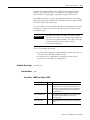
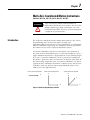
Introduction . . . . . . . . . . . . . . . . . . . . . . . . . . . . . . . . . . . 7-1
Using Different Termination Types When Blending Instructions.
7-3
Choose a termination type . . . . . . . . . . . . . . . . . . . . . . . . . 7-9
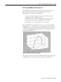
How do I get a triangular velocity profile?. . . . . . . . . . . . . 7-11
Blending Moves at Different Speeds . . . . . . . . . . . . . . . . . 7-12
Motion Coordinated Linear Move (MCLM). . . . . . . . . . . . . 7-13
Publication 1756-RM007G-EN-P - May 2005
Table of Contents
8
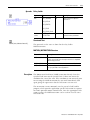
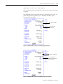
Operands: . . . . . . . . . . . . . . . . . . . . . . . . . . .
Description. . . . . . . . . . . . . . . . . . . . . . . . . . .
MCLM Move Type Examples . . . . . . . . . . . . . .
MCLM Instruction With Rotary Axes Examples .
Merge Example. . . . . . . . . . . . . . . . . . . . . . . .
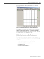
Additional Note On Merging Instructions . . . . .
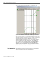
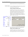
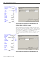
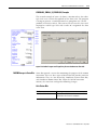
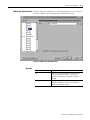
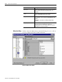
MCLM Target Position Entry Dialog Box . . . . .
Arithmetic Status Flags: . . . . . . . . . . . . . . . . . .
Fault Conditions: . . . . . . . . . . . . . . . . . . . . . .
Error Codes: . . . . . . . . . . . . . . . . . . . . . . . . . .
Extended Error Codes: . . . . . . . . . . . . . . . . . .
MCLM Changes to Status Bits: . . . . . . . . . . . . .
Example: . . . . . . . . . . . . . . . . . . . . . . . . . . . .
Motion Coordinated Circular Move (MCCM) . . . . .
Operands: . . . . . . . . . . . . . . . . . . . . . . . . . . .
Description: . . . . . . . . . . . . . . . . . . . . . . . . . .
Two Dimensional Arc Examples . . . . . . . . . . .
Two Dimensional Full Circle Example . . . . . . .
MCCM with Rotary Axes Examples . . . . . . . . .
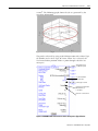
Three Dimensional Arcs . . . . . . . . . . . . . . . . .
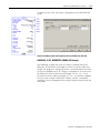
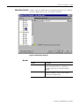
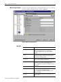
MCCM Target Position Entry Dialog Box . . . . .
Arithmetic Status Flags: . . . . . . . . . . . . . . . . . .
Fault Conditions: . . . . . . . . . . . . . . . . . . . . . .
Error Codes: . . . . . . . . . . . . . . . . . . . . . . . . . .
Extended Error Codes: . . . . . . . . . . . . . . . . . .
Circular Error Examples . . . . . . . . . . . . . . . . .
MCCM Changes to Status Bits: . . . . . . . . . . . . .
Example: . . . . . . . . . . . . . . . . . . . . . . . . . . . .
Circular Programming Reference Guide . . . . . .
Motion Coordinated Change Dynamics (MCCD) . .
Operands: . . . . . . . . . . . . . . . . . . . . . . . . . . .
Description: . . . . . . . . . . . . . . . . . . . . . . . . . .
Arithmetic Status Flags: . . . . . . . . . . . . . . . . . .
Fault Conditions: . . . . . . . . . . . . . . . . . . . . . .
Error Codes: . . . . . . . . . . . . . . . . . . . . . . . . . .
Extended Error Codes: . . . . . . . . . . . . . . . . . .
MCCD Changes to Status Bits: . . . . . . . . . . . . .
Example: . . . . . . . . . . . . . . . . . . . . . . . . . . . .
Motion Coordinated Stop (MCS) . . . . . . . . . . . . . .
Operands: . . . . . . . . . . . . . . . . . . . . . . . . . . .
Description: . . . . . . . . . . . . . . . . . . . . . . . . . .
Arithmetic Status Flags: . . . . . . . . . . . . . . . . . .
Fault Conditions: . . . . . . . . . . . . . . . . . . . . . .
Error Codes: . . . . . . . . . . . . . . . . . . . . . . . . . .
Extended Error Codes: . . . . . . . . . . . . . . . . . .
MCS Changes to Status Bits: . . . . . . . . . . . . . .
Example: . . . . . . . . . . . . . . . . . . . . . . . . . . . .
Publication 1756-RM007G-EN-P - May 2005
.
.
.
.
.
.
.
.
.
.
.
.
.
.
.
.
.
.
.
.
.
.
.
.
.
.
.
.
.
.
.
.
.
.
.
.
.
.
.
.
.
.
.
.
.
.
.
.
.
.
.
.
.
.
.
.
.
.
.
.
.
.
.
.
.
.
.
.
.
.
.
.
.
.
.
.
.
.
.
.
.
.
.
.
.
.
.
.
.
.
.
.
.
.
.
.
.
.
.
.
.
.
.
.
.
.
.
.
.
.
.
.
.
.
.
.
.
.
.
.
.
.
.
.
.
.
.
.
.
.
.
.
.
.
.
.
.
.
.
.
.
.
.
.
.
.
.
.
.
.
.
.
.
.
.
.
.
.
.
.
.
.
.
.
.
.
.
.
.
.
.
.
.
.
.
.
.
.
.
.
.
.
.
.
.
.
.
.
.
.
.
.
.
.
.
.
.
.
.
.
.
.
.
.
.
.
.
.
.
.
.
.
.
.
.
.
.
.
.
.
.
.
.
.
.
.
.
.
.
.
.
.
.
.
.
.
.
.
.
.
.
.
.
.
.
.
.
.
.
.
.
.
.
.
.
.
.
.
.
.
.
.
.
.
.
.
.
.
.
.
.
.
.
.
.
.
.
.
.
.
.
.
7-13
7-15
7-17
7-20
7-27
7-28
7-29
7-31
7-31
7-31
7-32
7-33
7-35
7-36
7-36
7-39
7-42
7-52
7-54
7-58
7-66
7-68
7-68
7-69
7-70
7-72
7-75
7-77
7-77
7-79
7-79
7-81
7-85
7-85
7-86
7-86
7-87
7-88
7-89
7-89
7-90
7-92
7-92
7-92
7-93
7-93
7-94
Table of Contents
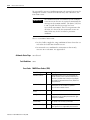
Motion Coordinated Shutdown (MCSD) . . . .
Operands: . . . . . . . . . . . . . . . . . . . . . . .
Description: . . . . . . . . . . . . . . . . . . . . . .
Arithmetic Status Flags: . . . . . . . . . . . . . .
Fault Conditions: . . . . . . . . . . . . . . . . . .
Error Codes: . . . . . . . . . . . . . . . . . . . . . .
MCSD Changes to Status Bits: . . . . . . . . .
Example: . . . . . . . . . . . . . . . . . . . . . . . .
Motion Coordinated Shutdown Reset (MCSR)
Operands: . . . . . . . . . . . . . . . . . . . . . . .
Description: . . . . . . . . . . . . . . . . . . . . . .
Arithmetic Status Flags: . . . . . . . . . . . . . .
Fault Conditions: . . . . . . . . . . . . . . . . . .
Error Codes: . . . . . . . . . . . . . . . . . . . . . .
MCSR Changes to Status Bits: . . . . . . . . .
Example: . . . . . . . . . . . . . . . . . . . . . . . .
9
.
.
.
.
.
.
.
.
.
.
.
.
.
.
.
.
.
.
.
.
.
.
.
.
.
.
.
.
.
.
.
.
.
.
.
.
.
.
.
.
.
.
.
.
.
.
.
.
.
.
.
.
.
.
.
.
.
.
.
.
.
.
.
.
.
.
.
.
.
.
.
.
.
.
.
.
.
.
.
.
.
.
.
.
.
.
.
.
.
.
.
.
.
.
.
.
.
.
.
.
.
.
.
.
.
.
.
.
.
.
.
.
.
.
.
.
.
.
.
.
.
.
.
.
.
.
.
.
.
.
.
.
.
.
.
.
.
.
.
.
.
.
.
.
.
.
.
.
.
.
.
.
.
.
.
.
.
.
.
7-94
7-94
7-95
7-95
7-96
7-96
7-96
7-97
7-97
7-97
7-98
7-99
7-99
7-99
7-99
7-100
.
.
.
.
.
.
.
.
.
.
.
.
.
.
.
.
.
.
.
.
.
.
.
.
.
.
.
.
.
.
.
.
.
.
.
.
.
.
.
.
.
.
.
.
.
.
.
.
.
.
.
.
.
.
.
.
.
.
.
.
.
.
.
.
.
.
.
.
.
.
.
.
.
.
.
.
.
.
.
.
.
.
.
.
.
.
.
.
.
.
.
.
.
.
.
.
.
.
.
.
.
.
.
.
.
.
.
.
.
.
.
.
.
.
.
.
.
.
.
.
.
.
.
.
.
.
.
.
.
.
.
.
.
.
.
.
.
.
.
.
.
.
.
.
.
.
.
.
.
.
.
.
.
.
.
.
.
.
.
.
.
.
.
.
.
.
.
.
.
.
.
.
.
.
.
.
.
.
.
.
.
.
.
.
.
.
.
.
.
.
.
.
.
.
.
.
.
.
.
.
.
.
.
.
.
.
.
.
.
.
.
.
.
.
.
.
.
.
.
.
.
.
.
.
.
.
.
.
.
.
.
.
.
.
.
.
.
.
.
.
.
.
.
.
.
.
.
.
.
.
.
.
.
.
.
.
.
.
.
.
.
.
.
.
.
.
.
.
.
.
.
.
.
.
.
.
.
.
.
.
.
.
.
.
.
.
.
.
.
.
.
.
.
.
.
.
.
Chapter 8
Motion Direct Commands
Introduction . . . . . . . . . . . . . . . . . . . . . . .
Supported Commands . . . . . . . . . . . . . . . .
Accessing Motion Direct Commands . . . . . .
From the Main Menu . . . . . . . . . . . . . .
From Group in the Controller Organizer
From Axis in the Controller Organizer . .
User Interface . . . . . . . . . . . . . . . . . . . . . .
Motion Direct Commands. . . . . . . . . . . . . .
Motion State Commands. . . . . . . . . . . . . . .
Motion Servo On . . . . . . . . . . . . . . . . .
Operands: . . . . . . . . . . . . . . . . . . . . . .
Motion Servo Off . . . . . . . . . . . . . . . . .
Operands: . . . . . . . . . . . . . . . . . . . . . .
Motion Axis Shutdown . . . . . . . . . . . . .
Operands: . . . . . . . . . . . . . . . . . . . . . .
Motion Axis Shutdown Reset. . . . . . . . .
Operands: . . . . . . . . . . . . . . . . . . . . . .
Motion Direct Drive On . . . . . . . . . . . .
Operands: . . . . . . . . . . . . . . . . . . . . . .
Motion Direct Drive Off . . . . . . . . . . . .
Operands: . . . . . . . . . . . . . . . . . . . . . .
Motion Axis Fault Reset. . . . . . . . . . . . .
Operands: . . . . . . . . . . . . . . . . . . . . . .
Motion Move Commands . . . . . . . . . . . . . .
Motion Axis Stop . . . . . . . . . . . . . . . . .
Operands: . . . . . . . . . . . . . . . . . . . . . .
Motion Axis Home . . . . . . . . . . . . . . . .
Operands: . . . . . . . . . . . . . . . . . . . . . .
Motion Axis Jog . . . . . . . . . . . . . . . . . .
.
.
.
.
.
.
.
.
.
.
.
.
.
.
.
.
.
.
.
.
.
.
.
.
.
.
.
.
.
8-1
8-1
8-2
8-3
8-4
8-7
8-8
8-11
8-12
8-12
8-12
8-13
8-13
8-14
8-14
8-15
8-15
8-16
8-16
8-17
8-17
8-18
8-18
8-19
8-19
8-19
8-20
8-20
8-21
Publication 1756-RM007G-EN-P - May 2005
Table of Contents
10
Operands: . . . . . . . . . . . . . . . . . . .
Motion Axis Move. . . . . . . . . . . . . .
Operands: . . . . . . . . . . . . . . . . . . .
Motion Axis Gear . . . . . . . . . . . . . .
Operands: . . . . . . . . . . . . . . . . . . .
Motion Change Dynamics . . . . . . . .
Operands: . . . . . . . . . . . . . . . . . . .
Motion Redefine Position . . . . . . . .
Operands: . . . . . . . . . . . . . . . . . . .
Motion Group Commands . . . . . . . . . .
Motion Group Stop . . . . . . . . . . . . .
Operands: . . . . . . . . . . . . . . . . . . .
Motion Group Shutdown . . . . . . . .
Operands: . . . . . . . . . . . . . . . . . . .
Motion Group Shutdown Reset . . . .
Operands: . . . . . . . . . . . . . . . . . . .
Motion Group Strobe Position . . . . .
Operands: . . . . . . . . . . . . . . . . . . .
Motion Event Commands . . . . . . . . . . .
Motion Arm Watch . . . . . . . . . . . . .
Operands: . . . . . . . . . . . . . . . . . . .
Motion Disarm Watch . . . . . . . . . . .
Operands: . . . . . . . . . . . . . . . . . . .
Motion Arm Registration . . . . . . . . .
Operands: . . . . . . . . . . . . . . . . . . .
Motion Disarm Registration . . . . . . .
Operands: . . . . . . . . . . . . . . . . . . .
Motion Direct Command Error Process .
Transition States . . . . . . . . . . . . . . .
.
.
.
.
.
.
.
.
.
.
.
.
.
.
.
.
.
.
.
.
.
.
.
.
.
.
.
.
.
.
.
.
.
.
.
.
.
.
.
.
.
.
.
.
.
.
.
.
.
.
.
.
.
.
.
.
.
.
.
.
.
.
.
.
.
.
.
.
.
.
.
.
.
.
.
.
.
.
.
.
.
.
.
.
.
.
.
.
.
.
.
.
.
.
.
.
.
.
.
.
.
.
.
.
.
.
.
.
.
.
.
.
.
.
.
.
.
.
.
.
.
.
.
.
.
.
.
.
.
.
.
.
.
.
.
.
.
.
.
.
.
.
.
.
.
.
.
.
.
.
.
.
.
.
.
.
.
.
.
.
.
.
.
.
.
.
.
.
.
.
.
.
.
.
.
.
.
.
.
.
.
.
.
.
.
.
.
.
.
.
.
.
.
.
.
.
.
.
.
.
.
.
.
.
.
.
.
.
.
.
.
.
.
.
.
.
.
.
.
.
.
.
.
.
.
.
.
.
.
.
.
.
.
.
.
.
.
.
.
.
.
.
.
.
.
.
.
.
.
.
.
.
.
.
.
.
.
.
.
.
.
.
.
.
.
.
.
.
.
.
.
.
.
.
.
.
.
.
.
.
.
.
.
.
.
.
.
.
.
.
.
.
.
.
.
.
.
.
.
.
.
.
.
.
.
.
.
.
.
.
.
.
.
.
.
.
.
.
.
.
.
.
.
.
.
.
.
.
.
.
.
.
.
.
.
.
.
.
.
.
.
.
.
.
.
.
.
.
.
.
.
.
.
.
.
.
.
.
.
.
.
.
.
.
.
.
.
.
.
.
.
.
.
.
.
.
.
.
.
.
.
.
.
.
.
.
.
.
.
.
.
.
.
.
.
.
.
.
.
.
.
.
.
.
.
.
8-21
8-22
8-23
8-24
8-24
8-26
8-26
8-27
8-28
8-28
8-28
8-29
8-29
8-30
8-30
8-30
8-31
8-31
8-32
8-32
8-32
8-33
8-33
8-34
8-34
8-35
8-35
8-36
8-38
.
.
.
.
.
.
.
.
.
.
.
.
.
.
.
.
.
.
.
.
.
.
.
.
.
.
.
.
.
.
.
.
.
.
.
.
.
.
.
.
.
.
.
.
.
.
.
.
.
.
.
.
.
.
.
.
.
.
.
.
.
.
.
.
.
.
.
.
.
.
.
.
.
.
.
.
.
.
.
.
.
.
.
.
.
.
.
.
.
.
.
.
.
.
.
.
.
.
.
.
.
.
.
.
.
.
.
.
.
.
.
.
.
.
.
.
.
.
.
.
.
.
.
.
.
.
.
.
.
.
.
.
.
.
.
.
.
.
.
.
.
.
.
.
.
.
.
.
.
.
.
.
.
.
.
.
.
.
.
.
.
.
.
.
.
.
.
.
.
.
.
.
.
.
.
.
.
.
.
.
.
.
. A-1
. A-1
. A-1
. A-6
A-14
A-23
A-27
A-28
A-30
A-32
A-32
A-33
A-34
Appendix A
Structures
Introduction. . . . . . . . . . . . . . . . . . . .
AXIS Structures . . . . . . . . . . . . . . . . .
AXIS_CONSUMED Structure . . . . .
AXIS_SERVO Structure . . . . . . . . .
AXIS_SERVO_DRIVE Structure. . . .
AXIS_VIRTUAL Structure . . . . . . . .
MOTION_GROUP Structure . . . . . . . .
MOTION_INSTRUCTION Structure . . .
Coordinate System Control Structure . .
CAM Structure . . . . . . . . . . . . . . . . . .
CAM_PROFILE Structure. . . . . . . . . . .
OUTPUT_CAM Structure . . . . . . . . . .
OUTPUT_COMPENSATION Structure .
.
.
.
.
.
.
.
.
.
.
.
.
.
Appendix B
Structured Text Programming
Publication 1756-RM007G-EN-P - May 2005
Introduction. . . . . . . . . . . . . . . . . . . . . . . . . . . . . . . . . . . . B-1
Table of Contents
Index
Structured Text Syntax . . . . . . . . . . . . . . . . . . .
Assignments . . . . . . . . . . . . . . . . . . . . . . . . . .
Specify a non-retentive assignment . . . . . . .
Assign an ASCII character to a string . . . . . .
Expressions . . . . . . . . . . . . . . . . . . . . . . . . . . .
Use arithmetic operators and functions . . . .
Use relational operators . . . . . . . . . . . . . . .
Use logical operators . . . . . . . . . . . . . . . . .
Use bitwise operators . . . . . . . . . . . . . . . . .
Determine the order of execution . . . . . . . .
Instructions . . . . . . . . . . . . . . . . . . . . . . . . . . .
Constructs . . . . . . . . . . . . . . . . . . . . . . . . . . . .
Some key words are reserved for future use
IF...THEN . . . . . . . . . . . . . . . . . . . . . . . . . . . .
CASE...OF . . . . . . . . . . . . . . . . . . . . . . . . . . . .
FOR…DO . . . . . . . . . . . . . . . . . . . . . . . . . . . .
WHILE…DO . . . . . . . . . . . . . . . . . . . . . . . . . .
REPEAT…UNTIL . . . . . . . . . . . . . . . . . . . . . . .
Comments . . . . . . . . . . . . . . . . . . . . . . . . . . . .
Rockwell Automation Support . . . . . . . . . . . . .
Installation Assistance . . . . . . . . . . . . . . . . .
New Product Satisfaction Return . . . . . . . . .
.
.
.
.
.
.
.
.
.
.
.
.
.
.
.
.
.
.
.
.
.
.
.
.
.
.
.
.
.
.
.
.
.
.
.
.
.
.
.
.
.
.
.
.
.
.
.
.
.
.
.
.
.
.
.
.
.
.
.
.
.
.
.
.
.
.
.
.
.
.
.
.
.
.
.
.
.
.
.
.
.
.
.
.
.
.
.
.
.
.
.
.
.
.
.
.
.
.
.
.
.
.
.
.
.
.
.
.
.
.
.
.
.
.
.
.
.
.
.
.
.
.
.
.
.
.
.
.
.
.
.
.
.
.
.
.
.
.
.
.
.
.
.
.
.
.
.
.
.
.
.
.
.
.
.
.
.
.
.
.
.
.
.
.
.
.
.
.
.
.
.
.
.
.
.
.
11
. B-1
. B-2
. B-3
. B-4
. B-4
. B-6
. B-7
. B-9
B-10
B-10
B-11
B-12
B-12
B-13
B-16
B-19
B-22
B-25
B-28
. 1-2
. 1-2
. 1-2
Back Cover
Publication 1756-RM007G-EN-P - May 2005
Table of Contents
12
Publication 1756-RM007G-EN-P - May 2005
Chapter
1
Motion Concepts
Introduction
This chapter covers concepts that are common to all the motion
instructions. It contains information on using motion parameters,
instruction timing, types of timing sequences, and
MOTION_INSTRUCTION structure and its members.
The motion instruction set consists of six groups of instructions.
Group:
For more information, see:
Motion state instructions
Chapter 2
Motion move instructions
Chapter 3
Motion group instructions
Chapter 4
Motion event instructions
Chapter 5
Motion configuration instructions
Chapter 6
Coordinated Motion instructions
Chapter 7
These instructions operate on one or more axes. You must identify
and configure axes before you can use them. For more information
about configuring an axis, refer to the ControlLogix Motion Module
Setup and Configuration Manual, publication 1756-UM006.
Using Motion Parameters
Motion Status and Configuration Parameters
You can read motion status and configuration parameters in your
ladder logic program using two methods.
Method
Directly accessing the
MOTION_GROUP and AXIS
structures
Using the GSV instruction
Example
• axis faults
• motion status
• servo status
• actual position
• command position
• actual velocity
For more information
See appendix A
structures
See Logix5000
Controller Instruction
Set Reference Manual,
Publication
1756-RM003.
Modifying Motion Configuration In your ladder logic program, you can modify motion configuration
Parameters parameters using the SSV instruction. For example, you can change
position loop gain, velocity loop gain, and current limits.
1
Publication 1756-RM007G-EN-P - May 2005
1-2
Motion Concepts
For more information about the SSV instruction, see the Logix5000
Controller Instruction Set Reference Manual, publication 1756-RM003.
For more information about motion instructions and creating
application programs, see the ControlLogix Motion Module Setup and
Configuration Manual, publication 1756-UM006.
Instruction Timing
Motion instructions use three types of timing sequences.
Timing type:
Description:
Immediate
The instruction completes in one scan.
Message
The instruction completes over several scans because the instruction
sends messages to the servo module.
Process
The instruction could take an indefinite amount of time to complete.
Immediate Type Instructions Immediate type motion instructions execute to completion in one
scan. If the controller detects an error during the execution of these
instructions, the error status bit sets and the operation ends.
Examples of immediate type instructions include the:
• Motion Change Dynamics (MCD) instruction
• Motion Group Strobe Position (MGSP) instruction
Immediate instructions work as follows:
1. When the rung that contains the motion instruction becomes
true, the controller:
• Sets the enable (.EN) bit.
• Clears the done (.DN) bit.
• Clears the error (.ER) bit.
The controller executes the instruction completely.
2.
If the controller:
Does not detect an error when the
instruction executes
Detects an error when the instruction
executes
Then:
The controller sets the .DN bit.
The controller sets the .ER bit and
stores an error code in the control
structure.
3. The next time the rung becomes false after either the .DN or .ER
bit sets, the controller clears the .EN bit.
Publication 1756-RM007G-EN-P - May 2005
Motion Concepts
1-3
4. The controller can execute the instruction again when the rung
becomes true.
.EN
.DN
.ER
Scan
rung
true
Scan
rung
true
Scan
rung
false
Scan
rung
true
Figure 1.1 Immediate Type Instructions - Rung Conditions
Message Type Instructions Message type motion instructions send one or more messages to the
servo module.
Examples of message type instructions include the:
• Motion Direct Drive On (MDO) instruction
• Motion Redefine Position (MRP) instruction
Message type instructions work as follows:
1. When the rung that contains the motion instruction becomes
true, the controller:
• Sets the enable (.EN) bit.
• Clears the done (.DN) bit.
• Clears the error (.ER) bit.
2. The controller begins to execute the instruction by setting up a
message request to the servo module.
The remainder of the instruction executes in parallel to the
program scan.
3. The controller checks if the servo module is ready to receive a
new message.
4. The controller places the results of the check in the message
status word of the control structure.
5. When the module is ready, the controller constructs and
transmits the message to the module.
Publication 1756-RM007G-EN-P - May 2005
1-4
Motion Concepts
This process may repeat several times if the instruction requires
multiple messages.
6.
If the controller:
Does not detect an error when the
instruction executes
Detects an error when the instruction
executes
Then:
The controller sets the .DN bit if all
messaging to the module is completed.
The controller sets the .ER bit and
stores an error code in the control
structure.
7. The next time the rung becomes false after either the .DN or .ER
bit sets, the controller clears the .EN bit.
8. When the rung becomes true, the controller can execute the
instruction again.
.EN
.DN
.ER
Scan
rung
true
Scan
rung
false
Execution
complete
Scan
rung
false
Scan
rung
true
Figure 1.2 Message Type Instructions - Rung Conditions
Process Type Instructions Process type motion instructions initiate motion processes that can
take an indefinite amount of time to complete.
Examples of process type instructions include the:
• Motion Arm Watch Position (MAW) instruction
• Motion Axis Move (MAM) instruction
Process type instructions work as follows:
1. When the rung that contains the motion instruction becomes
true, the controller:
•
•
•
•
Publication 1756-RM007G-EN-P - May 2005
Sets the enable (.EN) bit.
Clears the done (.DN) bit.
Clears the error (.ER) bit.
Clears the process complete (.PC) bit.
Motion Concepts
1-5
• Sets the in process (.IP) bit.
2. The controller initiates the motion process.
3.
If:
Then the controller:
The controller does not detect an error
• Sets the .DN bit.
when the instruction executes
• Sets the in process (.IP) bit.
The controller detects an error when
• Sets the .ER bit.
the instruction executes
• Stores an error code in the control
structure.
The controller detects another
Clears the .IP bit for that instance.
instance of the motion instruction
The motion process reaches the point Sets the .DN bit.
where the instruction can be executed
again
For some process type instructions, like
MAM, this occurs on the first scan. For
others, like MAH, the.DN bit is not set
until the entire homing process is
complete.
One of the following occurs during the Clears the .IP bit.
motion process:
• The motion process completes
• Another instance of the
instruction executes
• Another instruction stops the
motion process
• A motion fault stops the motion
process
4. After the initiation of the motion process, the program scan can
continue.
The remainder of the instruction and the control process
continue in parallel with the program scan.
5. The next time the rung becomes false after either the .DN bit or
the .ER bit sets, the controller clears the .EN bit.
Publication 1756-RM007G-EN-P - May 2005
1-6
Motion Concepts
6. When the rung becomes true, the instruction can execute again.
.EN
.DN
.ER
.IP
.PC
Scan
Scan
Execution Scan
Process
rung true rung false complete rung false complete
Figure 1.3 Process Type Instructions - Rung Conditions
Publication 1756-RM007G-EN-P - May 2005
Motion Concepts
Using the Motion
Instruction Structure
1-7
The controller uses the MOTION_INSTRUCTION structure to store
status information during the execution of motion instructions. Every
motion instruction has an operand that requires a motion instruction
structure. For each motion instruction you use, you must define a
unique motion instruction structure. The structure of the motion
instruction structure is shown below:
Figure 1.4 Motion instruction Structure
Motion Instruction Structure
Mnemonic:
Data Type:
Description:
.EN
BOOL
The enable bit indicates that the instruction is enabled ( the
rung-in and rung-out condition is true).
.DN
BOOL
The done bit indicates that all calculations and messaging
(if any) are complete.
.ER
BOOL
The error bit indicates when the instruction is used illegally.
.IP
BOOL
The in process bit indicates that a process is being
executed.
.PC
BOOL
The process complete bit indicates that the operation is
complete.
The .DN bit sets after an instruction has completed
execution. The .PC bit sets when the initiated process has
completed.
.AC
BOOL
The Active Bit lets you know which instruction is controlling
the motion when you have instructions queued. It sets when
the instruction becomes active. It is reset when the Process
Complete bit is set or when the instruction is stopped.
.ACCEL
BOOL
The .ACCEL bit indicates that the velocity has increased for
the individual instruction that it is tied to i.e jog, move,
gearing
.DECEL
BOOL
The .DECEL bit indicates that the velocity has decreased for
the individual instruction that it is tied to i.e jog, move,
gearing.
.ERR
INT
The error value contains the error code associated with a
motion function. See page 1-8.
.STATUS
SINT
The message status value indicates the status condition of
any message associated with the motion function. See
page 1-10.
Publication 1756-RM007G-EN-P - May 2005
1-8
Motion Concepts
Mnemonic:
Data Type:
Description:
.STATE
SINT
The execution status value keeps track of the execution
state of a function. Many motion functions have several
steps and this value tracks these steps.
.SEGMENT
DINT
A segment is the distance from one point up to but, not
including the next point. A .SEGMENT gives the relative
position by segment number as the Cam is executing.
Error codes (.ERR)
Error Code
Error Message
Description
1
Reserved Error Code 1
Reserved for future use.
2
Reserved Error Code 2
Reserved for future use
3
Execution Collision
The instruction tried to execute while another instance of this instruction was
executing. This can occur when the controller executes a messaging instruction without
checking the .DN bit of the preceding instruction.
4
Servo On State Error
The instruction tried to execute on an axis with a closed servo loop.
5
Servo Off State Error
The instruction tried to execute on an axis with a servo loop that is not closed.
6
Drive On State Error
The axis drive is enabled.
7
Shutdown State Error
The axis is in the shutdown state.
8
Illegal Axis Type
The configured axis type is not correct.
9
Overtravel Condition
The instruction tried to execute in a direction that aggravates the current overtravel
condition.
10
Master Axis Conflict
The master axis reference is the same as the slave axis reference.
11
Axis Not Configured
At least one axis is not configured to a physical motion module or has not been assigned
to a Motion Group.
12
Servo Message Failure
Messaging to the servo module failed.
13
Parameter Out Of Range
The instruction tried to use a parameter that is outside the range limit.
14
Tune Process Error
The instruction cannot apply the tuning parameters because of an error in the run tuning
instruction.
15
Test Process Error
The instruction cannot apply the diagnostic parameters because of an error in the run
diagnostic test instruction.
16
Home In Process Error
The instruction tried to execute with homing in progress.
17
Axis Mode Not Rotary
The instruction tried to execute a rotary move on an axis that is not configured for rotary
operation.
18
Axis Type Unused
The axis type is configured as unused.
19
Group Not Synchronized
The motion group is not in the synchronized state. This could be caused by a missing
servo module or a misconfiguration.
20
Axis In Faulted State
The axis is in the faulted state.
21
Group In Faulted State
The group is in the faulted state.
22
Axis In Motion
An MSO (Motion Servo On) or MAH (Motion Axis Home) instruction was attempted
while the axis was in motion.
23
Illegal Dynamic Change
An instruction attempted an illegal change of dynamics.
Publication 1756-RM007G-EN-P - May 2005
Motion Concepts
1-9
Error Code
Error Message
Description
24
Illegal AC Mode Op
The controller attempted to execute an MDO, MSO, MAH, MAJ, MAM, MCD, MAPC,
MATC, MAG, MRAT, or MRHD instruction when the controller was in the test mode.
25
Illegal Instruction
You attempted to execute an instruction that is not correct.
26
Illegal Cam Length
The cam array is of an illegal length.
27
Illegal Cam Profile Length
The cam profile array is of an illegal length.
28
Illegal Cam Type
You have an illegal segment type in the cam element.
29
Illegal Cam Order
You have an illegal order of cam elements.
30
Cam Profile Being Calculated
You tried to execute a cam profile while it is being calculated.
31
Cam Profile Being Used
The cam profile array you tried to execute is in use.
32
Cam Profile Not Calculated
The cam profile array you tried to execute has not been calculated.
33
Position Cam Not Enabled
It attempted to execute an MAH instruction without a position cam in process.
34
Registration in Progress
A MAH instruction is trying to start while a registration is already running.
35
Illegal Execution Target
Either the Logix controller or the Output Cam module does not support the specified
Output Cam, axis, input or output.
36
Illegal Output Cam
Either the size of the Output Cam array is not supported or the value of one of its
members is out of range.
37
Illegal Output Compensation
Either the size of the Output Compensation array is not supported or the value of one of
its members is out of range.
38
Illegal Axis Data Type
The axis data type is illegal. It is incorrect for the operation.
39
Process Conflict
You have a conflict in your process. Test and Tune cannot be run at the same time.
40
Drive Locally Disabled
You are trying to run a MSO or MAH instruction when the drive is locally disabled.
41
Illegal Homing Config
The Homing configuration is illegal. You have an absolute homing instruction when the
Homing sequence is not immediate.
42
Shutdown Status Timeout
The MASD or MGSD instruction has timed out because it did not receive the shutdown
status bit. Usually a programmatic problem caused when either MASD or MGSD is
followed by a reset instruction which is initiated before the shutdown bit has been
received by the shutdown instruction.
43
Coordinate System Queue Full
You have tried to activate more motion instructions than the instruction queue can hold.
44
Circular Collinearity Error
You have drawn a line with three (3) points and no centerpoint (viapoint) or plane
(centerpoint) can be determined.
45
Circular Start End Error
You have specified one (1) point (radius) or “drawn a line” (centerpoint, viapoint) and no
centerpoint (radius) or plane (centerpoint, viapoint) can be determined.
46
Circular R1 R2 Mismatch Error
The programmed centerpoint is not equidistant from start and end point.
47
Circular Infinite Solution Error
Call Rockwell Automation Technical Support
48
Circular No Solutions Error
Call Rockwell Automation Technical Support
49
Circular Small R Error
|R| < 0.01. R is basically too small to be used in computations.
50
Coordinate System Not in Group The coordinate system tag is not associated with a motion group.
51
Invalid Actual Tolerance
You have set your Termination Type to Actual Position with a value of 0. This value is not
supported.
Publication 1756-RM007G-EN-P - May 2005
1-10
Motion Concepts
Error Code
Error Message
Description
52
Coordination Motion In Process
Error
At least one axis is currently undergoing coordinated motion in another coordinated
system.
54
Zero Max Decel
You have set the Decel Rate to zero. This is an illegal value for Decel Rate which,
inhibits start motion.
65
The selected axis exceeded the
maximum system travel limits
(position overflowed)
The axis moved too far and the controller can’t store the position. The range for position
depends on the conversion constant of the axis.
·
·
Maximum positive position = 2,147,483,647 / conversion constant of the axis
Maximum negative position = -2,147,483,648 / conversion constant of the axis
Suppose you have a conversion constant of 2,097,152 counts/inch. In that case:
• Maximum positive position = 2,147,483,647 / 2,097,152 counts/inch = 1023
inches
• Maximum negative position = -2,147,483,648 / 2,097,152 counts/inch = -1023
inches
To prevent this error:
• Set up soft travel limits that keep the axis within the position range.
• One way to get more travel is to use the max negative or max positive position as
your home position.
Example
Max -
If you set the home
position here…
Publication 1756-RM007G-EN-P - May 2005
0
Max +
…0 is in the middle of the
travel. This gives you twice
the travel that homing to 0
would give you.
Motion Concepts
1-11
Message Status (.STATUS)
Message
Status:
0x0
0x1
0x2
0x3
0x4
Description:
The message was successful.
The module is processing another message.
The module is waiting for a response to a previous message.
The response to a message failed.
The module is not ready for messaging.
Execution Status (.STATE) The execution status is always set to 0 when the controller sets the.EN
bit for a motion instruction. Other execution states depend on the
motion instruction.
Profile Segment (.SEGMENT) A segment is the distance from one point up to but, not including the
next point. A.SEGMENT instruction gives the relative position by
segment number as the Cam is executing.
Publication 1756-RM007G-EN-P - May 2005
1-12
Motion Concepts
Notes:
Publication 1756-RM007G-EN-P - May 2005
Chapter
2
Motion State Instructions
(MSO, MSF, MASD, MASR, MDO,MDF, MAFR)
ATTENTION
Introduction
Tags used for the motion control attribute of
instructions should only be used once. Re-use of the
motion control tag in other instructions can cause
unintended operation. This may result in damage to
equipment or personal injury.
Motion state control instructions directly control or change the
operating states of an axis. The motion state instructions are:
If you want to:
Enable the servo drive and activate the axis
servo loop.
Use this instruction:
MSO
Available in these languages:
relay ladder
structured text
Disable the servo drive and deactivate the axis
servo loop.
MSF
relay ladder
structured text
Force an axis into the shutdown operating
state. Once the axis is in the shutdown
operating state, the controller will block any
instructions that initiate axis motion.
MASD
Change an axis from an existing shutdown
operating state to an axis ready operating
state. If all of the axes of a servo module are
removed from the shutdown state as a result of
this instruction, the OK relay contacts for the
module will close.
MASR
Enable the servo drive and set the servo output
voltage of an axis.
MDO
relay ladder
structured text
relay ladder
structured text
relay ladder
structured text
Deactivate the servo drive and set the servo
output voltage to the output offset voltage.
MDF
relay ladder
structured text
Clear all motion faults for an axis.
MAFR
relay ladder
structured text
1
Publication 1756-RM007G-EN-P - May 2005
2-2
Motion State Instructions
The five operating states of an axis are:
Operating State:
Description:
Axis ready
This is the normal power-up state of the axis. In this state:
• the servo module drive enable output is inactive.
• servo action is disabled.
• no servo faults are present.
Direct drive control
This operating state allows the servo module DAC to directly
control an external drive. In this state:
• the servo module drive enable output is active.
• position servo action is disabled.
Servo control
This operating state allows the servo module to perform closed
loop motion. In this state:
• the servo module drive enable output is active.
• servo action is enabled.
• the axis is forced to maintain the commanded servo
position.
Axis faulted
In this operating state, a servo fault is present, and the status
of the drive enable output, the action of the servo, and the
condition of the OK contact depend on the faults and fault
actions that are present.
Shutdown
This operating state allows the OK relay contacts to open a set
of contacts in the E-stop string of the drive power supply. In this
state:
• the servo module drive enable output is inactive.
• servo action is disabled.
• the OK contact is open.
Motion Servo On (MSO)
Publication 1756-RM007G-EN-P - May 2005
Use the MSO instruction to activate the drive amplifier for the
specified axis and to activate the axis’ servo control loop.
Motion State Instructions
2-3
Operands: Relay Ladder
Operand:
Type:
Format:
Description:
Axis
AXIS_GENERIC
tag
Name of the axis to perform
operation on.
tag
Structure used to access
instruction status parameters.
AXIS_SERVO
AXIS_SERVO_DRIVE
Motion
control
MOTION_
INSTRUCTION
Structured Text
MSO(Axis,MotionControl);
The operands are the same as those for the relay ladder MSO
instruction.
MOTION_INSTRUCTION Structure
Mnemonic:
Description:
.EN (Enable) Bit 31
It is set when the rung makes a false-to-true transition and
remains set until the servo message transaction is completed
and the rung goes false.
.DN (Done) Bit 29
It is set when the axis’ servo action has been successfully
enabled and the drive enable and servo active status bits have
been set.
.ER (Error) Bit 28
It is set to indicate that the instruction detected an error, such
as if you specified an unconfigured axis.
Description: The Motion Servo On (MSO) instruction directly activates the drive
and enables the configured servo loops associated with a physical
servo axis. It can be used anywhere in a program, but should not be
used while the axis is moving. If this is attempted, the MSO instruction
generates an “Axis in Motion” error.
The MSO instruction automatically enables the specified axis by
activating the drive and by activating the associated servo loop. The
resulting state of the axis is referred to the Servo Control state.
The most common use of this instruction is to activate the servo loop
for the specified axis in its current position in preparation for
commanding motion.
Publication 1756-RM007G-EN-P - May 2005
2-4
Motion State Instructions
To successfully execute a MSO instruction, the targeted axis must be
configured as a Servo axis. If this condition is not met the instruction
errors.
IMPORTANT
The MSO instruction execution may take multiple
scans to execute because it requires transmission of a
message to the motion module and time for the drive
output to stabilize and the servo loop to activate. The
Done (.DN) bit is not set immediately, but only after
the axis is in the Servo Control state.
This is a transitional instruction:
• In relay ladder, toggle the rung-condition-in from cleared to set
each time the instruction should execute.
• In structured text, condition the instruction so that it only
executes on a transition. See Appendix C.
Arithmetic Status Flags: not affected
Fault Conditions: none
Error Codes: MSO Error Codes (.ERR)
Error Message:
Code:
Description:
Execution Collision
3
Attempted execution on an axis that already
has another instance of this instruction
executing. This situation is possible when
instructions that require messaging are
executed without Done (.DN) bit 29 run
qualification.
Shutdown State Error
7
Attempted execution with the axis in the
Shutdown state.
Illegal Axis Type
8
Attempted execution with the axis not
configured as servo.
Axis Not Configured
11
Passed axis value references an unconfigured
axis meaning the axis has not been assigned to
either a physical motion module channel or to a
motion group.
Servo Message Failure
12
Messaging to targeted motion module failed.
See Extended Error section for more
information on the cause of the error.
Axis Group Not
Synchronized
Publication 1756-RM007G-EN-P - May 2005
19
Attempted execution on an axis whose
associated axis group is not currently
synchronized.
Motion State Instructions
Error Message:
Code:
Description:
Axis in Faulted State
20
Attempted execution on an axis, which is in the
Faulted state.
Group in Faulted State
21
Attempted execution on an axis, which is in a
group, which is in the Faulted state.
Axis in Motion
22
Attempted execution on an axis, which is in
motion.
Illegal Controller Mode
Operation
24
Attempted execution when the processor is in
test mode.
Illegal Axis Data Type
38
Attempted execution on an axis with an axis
data type that does not support the instruction.
Drive Locally Disabled
40
You are trying to run an MSO instruction when
the drive is locally disabled.
2-5
Extended Error Codes: Extended Error Codes provide additional instruction specific
information for the Error Codes that are generic to many instructions.
The following Extended Error codes help to pinpoint the problem
when the MSO instruction receives a Servo Message Failure (12) error
message.
Extended Error
Code (decimal)
Associated Error Code
(decimal)
Meaning
Object Mode conflict
(12)
SERVO_MESSAGE_FAILURE
(12)
Axis is in shutdown.
Permission Denied
(15)
SERVO_MESSAGE_FAILURE
(12)
Enable input switch error.
(SERCOS)
Device in wrong state
(16)
SERVO_MESSAGE_FAILURE
(12)
Device state not correct for
action. (SERCOS)
MSO Changes to Status Bits Axis Status Bits
Bit Name:
State:
Meaning:
ServoActStatus
TRUE
Axis is in Servo Control state with the servo
loop active.
DriveEnableStatus
TRUE
The axis drive enable output is active.
Motion Status Bits
None
Example: When the input conditions are true, the controller enables the servo
drive and activates the axis servo loop configured by axis1.
Publication 1756-RM007G-EN-P - May 2005
2-6
Motion State Instructions
Relay Ladder
Figure 2.1 MSO Ladder Example
Structured Text
MSO(Axis0,MSO_1);
Motion Servo Off (MSF)
Use the MSF instruction to deactivate the drive output for the specified
axis and to deactivate the axis’ servo loop.
IMPORTANT
If you execute an MSF instruction while the axis is
moving, the axis coasts to an uncontrolled stop.
Operands: Relay Ladder
Operand:
Type:
Format:
Description:
Axis
AXIS_GENERIC
tag
Name of the axis to perform action
upon.
tag
Structure used to access
instruction status parameters.
AXIS_SERVO
AXIS_SERVO_DRIVE
Motion
control
MOTION_
INSTRUCTION
Structured Text
MSF(Axis,MotionControl);
Publication 1756-RM007G-EN-P - May 2005
The operands are the same as those for the relay ladder
MSF instruction.
Motion State Instructions
2-7
MOTION_INSTRUCTION Structure
Mnemonic:
Description:
.EN (Enable) Bit 31
It is set when the rung makes a false-to-true transition and
remains set until the servo message transaction is completed
and the rung goes false.
.DN (Done) Bit 29
It is set when the axis’ servo action been successfully disabled
and the drive enable and servo active status bits have both
been cleared.
.ER (Done) Bit 28
It is set to indicate that the instruction detected an error, such
as if you specified an unconfigured axis.
Description: The Motion Servo Off (MSF) instruction directly and immediately turns
off drive output and disables the servo loop on any physical servo
axis. This places the axis in the Axis Ready state. The MSF instruction
also disables any motion planners that may be active at the time of
execution. The MSF instruction requires no parameters – simply enter
or select the desired axis.
If the targeted axis does not appear in the list of available axes, the
axis has not been configured for operation. Use the Tag Editor to
create and configure a new axis.
You can use the MSF instruction to turn servo action OFF when you
must move the axis by hand. Since the position continues to be
tracked even with servo action OFF. When the servo loop is turned ON
again, by the MSO instruction, the axis is again under closed-loop
control, at the new position.
Note: The axis stopping behavior varies depending upon the
type of drive. In some cases the axis coasts to a stop and in
other cases the axis decelerates to a stop using the drive’s
available stopping torque.
To execute an MSF instruction successfully, the targeted axis must be
configured as a Servo axis. If this condition is not met, the instruction
errs. IF you have an Axis Type of Virtual the instructions errors
because with a Virtual Axis the servo action and drive enable status
are forced to always be true. A Consumed axis data type also errors
Publication 1756-RM007G-EN-P - May 2005
2-8
Motion State Instructions
because only the producing controller can change the state of a
consumed axis.
IMPORTANT
The MSF instruction execution may take multiple
scans to execute because it requires transmission of a
message to the motion module and time for the drive
output and servo loop to be fully deactivated. The
Done (.DN) bit is not set until this message has been
successfully transmitted and the axis transitions to
the Axis Ready state.
This is a transitional instruction:
• In relay ladder, toggle the rung-condition-in from cleared to set
each time the instruction should execute.
• In structured text, condition the instruction so that it only
executes on a transition. See Appendix C.
Arithmetic Status Flags: not affected
Fault Conditions: none
Error Codes: MSF Error Codes (.ERR)
Publication 1756-RM007G-EN-P - May 2005
Error Message:
Code:
Description:
Execution Collision
3
Attempted execution on an axis that already has
another instance of this instruction executing. This
situation is possible when instructions that require
messaging are executed without Done (.DN) bit 29
run qualification.
Illegal Axis Type
8
Attempted execution with the axis not configured as
servo.
Axis Not Configured
11
Passed axis value references an unconfigured axis
meaning the axis has not been assigned to a
physical motion module channel.
Servo Message
Failure
12
Messaging to targeted motion module failed.
Axis Group Not
Synchronized
19
Attempted execution on an axis whose associated
axis group is not currently synchronized.
Illegal Axis Data Type
38
Attempted execution on an axis with an Axis Data
Type that is not supported by the instruction.
Motion State Instructions
2-9
MSF Changes to Status Bits: Axis Status Bits
Bit Name
State
Meaning
ServoActionStatus
FALSE
Axis is in Servo On state with the servo loop
active.
DecelStatus
FALSE
Axis Drive Enable output is active.
Bit Name
State
Meaning
AccelStatus
FALSE
Axis is not Accelerating.
DecelStatus
FALSE
Axis is not Decelerating.
MoveStatus
FALSE
Axis is not Moving.
JogStatus
FALSE
Axis is not Jogging.
GearingStatus
FALSE
Axis is not Gearing.
HomingStatus
FALSE
Axis is not Homing.
StoppingStatus
FALSE
Axis is not Stopping.
PositionCamStatus
FALSE
Axis is not Position Camming.
TimeCamStatus
FALSE
Axis is not Time Camming.
PositionCamPendingStatus
FALSE
Axis does not have a Position Cam Pending.
TimeCamPendingStatus
FALSE
Axis does not have a Time Cam Pending.
GearingLockStatus
FALSE
Axis is not in a Gear Locked condition.
PositionCamLockStatus
FALSE
Axis is not in a Cam Locked condition.
Motion Status Bits
Example: When the input conditions are true, the controller disables the servo
drive and the axis servo loop configured by Axis0.
Relay Ladder
Figure 2.2 MSF Ladder Example
Structured Text
MSF(Axis0,MSF_1);
Motion Axis Shutdown
(MASD)
Use the MASD instruction to force a specified axis into the Shutdown
state. The Shutdown state of an axis is the condition where the drive
output is disabled, servo loop deactivated, and any available or
Publication 1756-RM007G-EN-P - May 2005
2-10
Motion State Instructions
associated OK solid-state relay contacts open. The axis will remain in
the Shutdown state until either an Axis or Group Shutdown Reset is
executed.
Operands: Relay Ladder
Operand:
Type:
Format:
Description:
Axis
AXIS_FEEDBACK
tag
The name of the axis to perform
operation on.
tag
Structure used to access
instruction status parameters.
AXIS_VIRTUAL
AXIS_GENERIC
AXIS_SERVO
AXIS_SERVO_DRIVE
Motion
control
MOTION_
INSTRUCTION
Structured Text
MASD(Axis,MotionControl);
The operands are the same as those for the relay ladder
MASD instruction.
MOTION_INSTRUCTION Structure
Mnemonic:
Description:
.EN (Enable) Bit 31
It is set when the rung makes a false-to-true transition and
remains set until the servo message transaction is completed
and the rung goes false.
.DN (Done) Bit 29
It is set when the axis have been successfully set to Shutdown
state.
.ER (Error) Bit 28
It is set to indicate that the instruction detected an error, such
as if you specified an unconfigured axis.
Description: The Motion Axis Shutdown (MASD) instruction directly and
immediately disables drive output, disables the servo loop, and opens
any associated OK contacts. This action places the axis into the
Shutdown state.
Another action initiated by the MASD instruction is the clearing of all
motion processes in progress and the clearing of all the motion status
bits. Associated with this action, the command also clears all motion
instruction IP bits that are currently set for the targeted axis.
The MASD instruction forces the targeted axis into the Shutdown state.
One of the unique characteristics of the Shutdown state is that, when
available, the OK solid state relay contact for the motion module or
Publication 1756-RM007G-EN-P - May 2005
Motion State Instructions
2-11
drive is Open. This feature can be used to open up the E-Stop string
that controls main power to the drive system. Note that there is
typically only one OK contact per motion module which means that
execution of an MASD instruction for either axis associated with a
given module opens the OK contact.
Another characteristic of the Shutdown state is that any instruction that
initiates axis motion is blocked from execution. Attempts to do so
result in an execution error. Only by executing one of the Shutdown
Reset instructions can motion be successfully initiated.
To successfully execute a MASD instruction, the targeted axis must be
configured as either a Servo or Feedback Only axis. If not, the
instruction errs.
The axis remains in the shutdown state until either a Motion Axis
Shutdown Reset (MASR) instruction or a Motion Group Shutdown
Reset (MGSR) instruction executes.
IMPORTANT
The MASD instruction execution may take multiple
scans to execute because it requires transmission of a
message to the motion module. Thus, the Done
(.DN) bit is not set until after this message is
successfully transmitted and the axis is in the
Shutdown state.
This is a transitional instruction:
• In relay ladder, toggle the rung-condition-in from cleared to set
each time the instruction should execute.
• In structured text, condition the instruction so that it only
executes on a transition. See Appendix C.
Arithmetic Status Flags: not affected
Fault Conditions: none
Publication 1756-RM007G-EN-P - May 2005
2-12
Motion State Instructions
Error Codes: MASD Error Codes (.ERR)
Error Message:
Code:
Description:
Execution Collision
3
Attempted execution on an axis that already has
another instance of this instruction executing. This
situation is possible when instructions that require
messaging are executed without Done (.DN) bit 29
run qualification.
Axis Not Configured
11
Passed axis value references an unconfigured axis
meaning the axis has not been assigned to a
physical motion module channel.
Servo Message
Failure
12
Messaging to targeted motion module failed.
Axis Type Unused
18
Attempted execution on an axis that is not
configured for use according the current Axis Type
configuration attribute.
Axis Group Not
Synchronized
19
Attempted execution on an axis whose associated
axis group is not currently synchronized.
Illegal axis Data Type
38
You attempted to execute an instruction on an Axis
Data Type that is not supported by the instruction.
Shutdown Status Time 42
Out
The MASD instruction failed to detect the assertion
of the Shutdown Status Bit within the established
fixed delay time period.
MASD Changes to Status Bits: Axis Status Bits
Bit Name:
State:
ServoActStatus
FALSE
Meaning:
• The axis is in the axis ready state.
• The servo loop is inactive.
DriveEnableStatus
FALSE
The drive enable output is inactive.
ShutdownStatus
TRUE
The axis is in the shutdown state.
Motion Status Bits
Publication 1756-RM007G-EN-P - May 2005
Bit Name
State
Meaning
AccelStatus
FALSE
Axis is not Accelerating
DecelStatus
FALSE
Axis is not Decelerating
MoveStatus
FALSE
Axis is not Moving
JogStatus
FALSE
Axis is not Jogging
GearingStatus
FALSE
Axis is not Gearing
HomingStatus
FALSE
Axis is not Homing
StoppingStatus
FALSE
Axis is not Stopping
PositionCamStatus
FALSE
Axis is not Position Camming
TimeCamStatus
FALSE
Axis is not Time Camming
Motion State Instructions
2-13
Bit Name
State
Meaning
PositionCamPendingStatus
FALSE
Axis does not have a Position Cam Pending.
TimeCamPendingStatus
FALSE
Axis does not have a Time Cam Pending.
GearingLockStatus
FALSE
Axis is not in a Gear Locked condition
PositionCamLockStatus
FALSE
Axis is not in a Cam Locked condition
Example: When the input conditions are true, the controller forces axis1 into the
shutdown operating state.
Relay Ladder
Figure 2.3 MASD Ladder Example
Structured Text
MASD(Axis0,MASD_1);
Motion Axis Shutdown
Reset (MASR)
Use the MASR instruction to transition an axis from an existing
Shutdown state to an Axis Ready state. All faults associated with the
specified axis are automatically cleared. If, as a result of this
instruction, all axes of the associated motion module are no longer in
the Shutdown condition, the OK relay contacts for the module close.
Publication 1756-RM007G-EN-P - May 2005
2-14
Motion State Instructions
Operands: Relay Ladder
Operand:
Type:
Format:
Description:
Axis
AXIS_FEEDBACK
tag
Name of the axis to perform
operation on.
tag
Structure used to access
instruction status parameters.
AXIS_VIRTUAL
AXIS_GENERIC
AXIS_SERVO
AXIS_SERVO_DRIVE
Motion
control
MOTION_
INSTRUCTION
Structured Text
MASR(Axis,MotionControl);
The operands are the same as those for the relay ladder
MASR instruction.
MOTION_INSTRUCTION Structure
Mnemonic:
Description:
.EN (Enable) Bit 31
It is set when the rung makes a false-to-true transition and
remains set until the servo message transaction is completed
and the rung goes false.
.DN (Done) Bit 29
It is set when the axis is successfully reset from Shutdown
state.
.ER (Error) Bit 28
It is set to indicate that the instruction detected an error, such
as if you specified an unconfigured axis.
Description: The Motion Axis Shutdown Reset (MASR) instruction clears all axis
faults and takes the specified axis out of the Shutdown state. If the
motion module supports an OK contact, and no other module axis is
in the Shutdown state, the MASR instruction results in closure of the
module’s OK solid-state relay contact. Regardless of the OK contact
condition, execution of the MASR places the axis into the Axis Ready
state.
Just as the MASD instruction forces the targeted axis into the
Shutdown state, the MASR instruction takes the axis out of the
Shutdown state into the Axis Ready state. One of the unique
characteristics of the Shutdown state is that any associated OK solid
state relay contact for the motion module is Open. If, as a result of an
MASR instruction there are no axes associated with a given motion
module in the Shutdown state, the OK relay contacts close as a result
of the MASR. This feature can be used to close the E-Stop string that
controls main power to the drive system and, thus, permit the
customer to reapply power to the drive. Note that there is typically
Publication 1756-RM007G-EN-P - May 2005
Motion State Instructions
2-15
only one OK contact per motion module which means that execution
of the MASR instruction may be required for all axes associated with a
given module for the OK contact to close.
To successfully execute a MASR instruction, the targeted axis must be
configured as either a Servo or Feedback Only axis. Otherwise, the
instruction errs.
IMPORTANT
The MASR instruction execution may take multiple
scans to execute because it requires transmission of a
message to the motion module. Thus, the Done
(.DN) bit is not set until after the message has been
successfully transmitted.
This is a transitional instruction:
• In relay ladder, toggle the rung-condition-in from cleared to set
each time the instruction should execute.
• In structured text, condition the instruction so that it only
executes on a transition. See Appendix C.
Arithmetic Status Flags: not affected
Fault Conditions: none
Error Codes: MASR Error Codes (.ERR)
Error Message:
Code:
Description:
Execution Collision
3
Attempted execution on an axis that already has
another instance of this instruction executing. This
situation is possible when instructions that require
messaging are executed without Done (.DN) bit 29
run qualification.
Axis Not Configured
11
Passed axis value references an unconfigured axis
meaning the axis has not been assigned to a
physical motion module channel.
Servo Message
Failure
12
Messaging to targeted motion module failed.
Axis Type Unused
18
Attempted execution on an axis that is not
configured for use according the current Axis Type
configuration attribute.
Axis Group Not
Synchronized
19
Attempted execution on an axis whose associated
axis group is not currently synchronized.
Illegal Axis Data Type
38
You attempted to execute an instruction on an Axis
Data Type that is not supported by the instruction.
Publication 1756-RM007G-EN-P - May 2005
2-16
Motion State Instructions
Status Bits: MASR Changes to Status Bits
Bit Name:
State:
Meaning:
ShutdownStatus
FALSE
The axis is not in the shutdown state.
Example: When the input conditions are true, the controller resets axis1 from a
previous shutdown operating state into an axis ready operating state.
Relay Ladder
Figure 2.4 MASR Ladder Example
Structured Text
MASR(Axis0,MASR_1);
Motion Direct Drive On
(MDO)
Use the MDO instruction in conjunction with motion modules that
support an external analog servo drive interface, e.g. the 1756–M02AE
or 1784-PM02AE servo module. This instruction activates the module’s
Drive Enable, enabling the external servo drive, and also sets the
servo module’s output voltage of the drive to the specified voltage
level. The value for Drive Output may be specified in Volts or % of
maximum axis’ Output Limit.
Operands: Relay Ladder
Operand:
Data Type:
Description:
Axis
Tag
Name of the axis to perform operation on.
Motion
control
MOTION_
INSTRUCTION Tag
Structure used to access instruction status
parameters.
Drive Output REAL
Voltage to output in % of servo Output Limit or
in Volts
Drive Units
Units in which the Drive Output value is
interpreted.
Boolean
Structured Text
MDO(Axis,MotionControl,
DriveOutput,DriveUnits);
Publication 1756-RM007G-EN-P - May 2005
The operands are the same as those for the relay ladder
MDO instruction.
Motion State Instructions
2-17
For the operands that require you to select from available options,
enter your selection as:
This operand:
DriveUnits
Has these options which you...
enter as text:
or enter as a number:
volts
0
percent
1
MOTION_INSTRUCTION Structure
Mnemonic:
Description:
.EN (Enable) Bit 31
It is set when the rung makes a false-to-true transition and
remains set until the servo message transaction is completed
and the rung goes false.
.DN (Done) Bit 29
It is set when the axis’ drive enable bit is activated and the
specified analog output is successfully applied.
.ER (Error) Bit 28
It is set to indicate that the instruction detected an error, such
as if you entered a Drive Output value that was too large.
Description: For motion module’s with an external servo drive interface, like the
1756–M02AE or 1784-PM02AE, the Motion Direct Drive On (MDO)
instruction can be used to directly enable the Drive Enable output of
the axis and set the analog output to a specified level determined by
the Drive Output parameter. The Drive Output parameter can be
expressed as a voltage, or as a percent of the maximum configured
output voltage value given by the Output Limit attribute.
The MDO instruction can only be used on a physical axis whose Axis
Type is configured for Servo. The instruction only executes when the
axis’ is in the Axis Ready state, i.e., servo action is OFF. The resulting
state of the axis is referred to as the Drive Control state.
The MDO instruction automatically enables the specified axis by
activating the appropriate Drive Enable output before setting the servo
module’s analog output to the specified voltage value. There is,
typically, a 500 msec delay between the activation of the drive enable
output and the setting of the analog output to the specified level to
allow the drive’s power structure to stabilize. To minimize drift during
this drive enabling delay, the output voltage to the drive is set to the
Output Offset attribute value (default is zero). Thereafter the output
voltage is given by the specified Drive Output value of the MDO
instruction and indicated by the Servo Output status attribute value.
The 16-bit DAC hardware associated with various Logix servo
modules limits the effective resolution of the Direct Drive Motion
Control to 305 µV or 0.003%. In the case of Direct Drive operation, the
module’s servo loop is inactive and bypassed. The Motion Direct
Publication 1756-RM007G-EN-P - May 2005
2-18
Motion State Instructions
Drive On instruction is only affected by the Servo Output Polarity
configuration bit, the Output Offset, and Output Limit attributes for
the axis. In the case where Output Limit configuration value is
reduced below the current output voltage value, the Servo Output
value is automatically clamped to the Output Limit value.
The most common use of this instruction is to provide an independent
programmable analog output as an open loop speed reference for an
external drive or for testing an external servo drive for closed loop
operation.
To successfully execute a MDO instruction, the targeted axis must be
configured as a Servo axis and be in the Axis Ready state, with servo
action off. If these conditions are not met the instruction errs.
IMPORTANT
The MDO instruction execution may take multiple
scans to execute because it requires transmission of a
message to the motion module and time for the drive
output to stabilize. The Done (.DN) bit is not set
until after the axis is in the Drive Control state.
This is a transitional instruction:
• In relay ladder, toggle the rung-condition-in from cleared to set
each time the instruction should execute.
• In structured text, condition the instruction so that it only
executes on a transition. See Appendix C.
Arithmetic Status Flags: not affected
Fault Conditions: none
Error Codes: MDO Error Codes (.ERR)
Publication 1756-RM007G-EN-P - May 2005
Error Message:
Code:
Description:
Execution Collision
3
Attempted execution on an axis that already has
another instance of this instruction executing. This
situation is possible when instructions that require
messaging are executed without Done (.DN) bit 29
run qualification.
Servo On State Error
4
Attempted execution with the axis in Servo On state
meaning that the targeted axis’ servo loop is
currently closed.
Shutdown State Error
7
Attempted execution with the axis in the Shutdown
state.
Motion State Instructions
Error Message:
Code:
Description:
Illegal Axis Type
8
Attempted execution with the axis not configured as
servo.
Axis Not Configured
11
Passed axis value references an unconfigured axis
meaning the axis has not been assigned to a
physical motion module channel.
Servo Message
Failure
12
Messaging to targeted motion module failed. See
Extended Error section for more information on the
cause of the error.
Axis Group Not
Synchronized
19
Attempted execution on an axis whose associated
axis group is not currently synchronized.
Axis in Faulted State
20
Attempted execution on an axis, which is in the
Faulted state.
Group in Faulted State 21
Attempted execution on an axis, which is in a group,
which is in the Faulted state.
Illegal Controller
Mode Operation
24
Attempted execution when the processor is in test
mode
Illegal Axis Data Type
38
Attempted execution on an axis whose Axis Data
Type is not supported by this instruction.
2-19
Extended Error Codes: Extended Error Codes provide additional instruction specific
information for the Error Codes that are generic to many instructions.
The following Extended Error codes help to pinpoint the problem
when the MDO instruction receives a Servo Message Failure (12) error
message.
Extended Error
Code (decimal)
Associated Error Code
(decimal)
Meaning
Object Mode conflict
(12)
SERVO_MESSAGE_FAILURE
(12)
Axis is in shutdown.
Status Bits: MDO Changes to Status Bits
Bit Name:
State:
Meaning:
DriveEnableStatus
TRUE
Axis is in Drive Control state with the
Drive Enable output active.
Example: When the input conditions are true, the controller activates the servo
drive for axis1 and sets the servo output voltage of axis1. In this
example, the output is 2% of the output value.
Publication 1756-RM007G-EN-P - May 2005
2-20
Motion State Instructions
Relay Ladder
Figure 2.5 MDO Ladder Example
Structured Text
MDO(Axis0,MDO_1,4,percent);
Motion Direct Drive Off
(MDF)
Use the MDF instruction to deactivate the servo drive and to set the
servo output voltage to the output offset voltage. The output offset
voltage is the output voltage that generates zero or minimal drive
motion. You can specify this value during axis configuration.
Operands: Relay Ladder
Operand:
Data Type:
Description:
Axis
Tag
Name of the axis to perform operation on.
Motion
control
MOTION_
INSTRUCTION Tag
Structure used to access instruction status
parameters.
Structured Text
MDF(Axis,MotionControl);
The operands are the same as those for the relay ladder
MDF instruction.
MOTION_INSTRUCTION Structure
Mnemonic:
Description:
.EN (Enable) Bit 31
It is set when the rung makes a false-to-true transition and
remains set until the servo message transaction is completed
and the rung goes false.
.DN (Done) Bit 29
It is set when the axis’ drive signals have been successfully
disabled and the drive enable status bit is cleared.
.ER (Error) Bit 28
It is set to indicate that the instruction detected an error, such
as if you specified an unconfigured axis.
Description: For motion module’s with an external servo drive interface, e.g. the
1756–M02AE, the Motion Direct Drive Off (MDF) instruction directly
Publication 1756-RM007G-EN-P - May 2005
Motion State Instructions
2-21
disables the motion module Drive Enable output of the specified
physical axis and also “zeroes” the modules’ servo output to the
external drive by applying the configured Output Offset value.
The MDF instruction is used to stop motion initiated by a preceding
MDO instruction and transition the axis from the Direct Drive Control
state back to the Axis Ready state.
To successfully execute an MDF instruction, the targeted axis must be
configured as either a Servo or Feedback Only axis. Otherwise, the
instruction errors.
IMPORTANT
The MDF instruction execution may take multiple
scans to execute because it requires transmission of a
message to the motion module. The Done (.DN) bit
is not set until after the message has been
successfully transmitted.
This is a transitional instruction:
• In relay ladder, toggle the rung-condition-in from cleared to set
each time the instruction should execute.
• In structured text, condition the instruction so that it only
executes on a transition. See Appendix C.
Arithmetic Status Flags: not affected
Fault Conditions: none
Error Codes: MDF Error Codes (.ERR)
Error Message:
Code:
Description:
Execution Collision
3
Attempted execution on an axis that already has
another instance of this instruction executing. This
situation is possible when instructions that require
messaging are executed without Done (.DN) bit 29
run qualification.
Servo On State Error
4
Attempted execution with the axis in Servo On state
meaning that the targeted axis’ servo loop is
currently closed.
Illegal Axis Type
8
Attempted execution with the axis not configured as
servo.
Publication 1756-RM007G-EN-P - May 2005
2-22
Motion State Instructions
Error Message:
Code:
Description:
Axis Not Configured
11
Passed axis value references an unconfigured axis
meaning the axis has not been assigned to a
physical motion module channel.
Axis Group Not
Synchronized
19
Attempted execution on an axis whose associated
axis group is not currently synchronized.
Illegal Axis Data Type
38
Attempted execution on an axis whose Axis Data
Type is not supported by this instruction.
MDF Changes to Status Bits: Axis Status Bits
Bit Name:
State:
Meaning:
DriveEnableStatus
FALSE
Axis is in Axis Ready state with the Drive
Enable output now active.
Example: When the input conditions are true, the controller deactivates the
servo drive for axis1 and sets the servo output voltage of axis_ to the
output offset value.
Relay Ladder
Figure 2.6 MDF Ladder Example
Structured Text
MDF(Axis0,MDF_1);
Motion Axis Fault Reset
(MAFR)
Use the MAFR instruction to clear all motion faults for an axis. This is
the only method for clearing axis motion faults.
IMPORTANT
Publication 1756-RM007G-EN-P - May 2005
The MAFR instruction removes the fault status, but
does not perform any other recovery, such as
enabling servo action. In addition, when the
controller removes the fault status, the condition that
generated the fault(s) may still exist. If the condition
is not corrected before using the MAFR instruction,
the axis immediately faults again.
Motion State Instructions
2-23
Operands: Relay Ladder
Operand:
Type:
Format:
Description:
Axis
AXIS_FEEDBACK
tag
Name of the axis to perform
operation on.
tag
Structure used to access
instruction status parameters.
AXIS_VIRTUAL
AXIS_GENERIC
AXIS_SERVO
AXIS_SERVO_DRIVE
Motion
control
MOTION_
INSTRUCTION
Structured Text
MAFR(Axis,MotionControl);
The operands are the same as those for the relay ladder
MAFR instruction.
MOTION_INSTRUCTION Structure
Mnemonic:
Description:
.EN (Enable) Bit 31
It is set when the rung makes a false-to-true transition and
remains set until the servo message transaction is completed
and the rung goes false.
.DN (Done) Bit 29
It is set when the axis’ faults have been successfully cleared.
.ER (Error) Bit 28
It is set to indicate that the instruction detected an error, such
as if you specified an unconfigured axis.
Description: The Motion Axis Fault Reset (MAFR) instruction directly clears the
specified fault status on the specified axis. It does not correct the
condition that caused the error. If the condition is not corrected prior
to executing the MAFR instruction the axis could immediately fault
again giving the appearance that the fault status was not reset.
This instruction is most commonly used as part of a fault handler
program, which provides application specific fault action in response
to various potential motion control faults. Once the appropriate fault
action is taken, the MAFR instruction can be used to clear all active
fault status bits.
Publication 1756-RM007G-EN-P - May 2005
2-24
Motion State Instructions
To successfully execute a MAFR instruction, the targeted axis must be
configured as either a Servo or Feedback Only axis. Otherwise, the
instruction errors.
IMPORTANT
The MAFR instruction execution may take multiple
scans to execute because it requires transmission of a
message to the motion module. The Done (.DN) bit
is not set until after this message has been
successfully transmitted. There is no guarantee that
all faults are cleared by this instruction as one or
more faults may be the result of a persistent
condition.
This is a transitional instruction:
• In relay ladder, toggle the rung-condition-in from cleared to set
each time the instruction should execute.
• In structured text, condition the instruction so that it only
executes on a transition. See Appendix C.
Arithmetic Status Flags: not affected
Fault Conditions: none
Error Codes: MAFR Error Codes (.ERR)
Publication 1756-RM007G-EN-P - May 2005
Error Message:
Code:
Description:
Execution Collision
3
Attempted execution on an axis that already has
another instance of this instruction executing. This
situation is possible when instructions that require
messaging are executed without Done (.DN) bit 29
run qualification.
Axis Not Configured
11
Passed axis value references an unconfigured axis
meaning the axis has not been assigned to a
physical motion module channel.
Servo Message
Failure
12
Messaging to targeted motion module failed.
Axis Type Unused
18
Attempted execution on an axis that is not
configured for use according the current Axis Type
configuration attribute.
Axis Group Not
Synchronized
19
Attempted execution on an axis whose associated
axis group is not currently synchronized.
Illegal Axis Data Type
38
You attempted to execute an instruction on an Axis
Data Type that is not supported by the instruction.
Motion State Instructions
2-25
MAFR Changes to Status Bits: None
MAFR Example: When the input conditions are true, the controller clears all motion
faults for axis1.
Relay Ladder
Figure 2.7 MAFR Ladder Example
Structured Text
MAFR(Axis0,MAFR_1);
Publication 1756-RM007G-EN-P - May 2005
2-26
Motion State Instructions
Notes:
Publication 1756-RM007G-EN-P - May 2005
Chapter
3
Motion Move Instructions
(MAS, MAH, MAJ, MAM, MAG, MCD, MRP, MCCP, MAPC,
MATC, MCSV)
ATTENTION
Introduction
Tags used for the motion control attribute of
instructions should only be used once. Re-use of the
motion control tag in other instructions can cause
unintended operation. This may result in damage to
equipment or personal injury.
The Move Control Instruction category includes all motion instructions
that cause or directly affect axis motion. These instructions include
moving, jogging, gearing, stopping, camming, etc. This category also
includes motion instructions that directly modify current axis position
that are typically used to reference the specified axis to some absolute
physical position of the axis. Instructions to redefine axis position and
perform a homing sequences fall under this category.
The motion move instructions are:
If you want to:
1
Use this instruction:
Available in these languages:
Initiate a controlled stop of any motion process
on an axis.
MAS
relay ladder
structured text
Home an axis.
MAH
relay ladder
structured text
Initiate a jog motion profile for an axis.
MAJ
relay ladder
structured text
Initiate a move profile for an axis.
MAM
relay ladder
structured text
Provide electronic gearing between any two
axes.
MAG
relay ladder
structured text
Change the speed, acceleration rate, or
deceleration rate of a move profile or a jog
profile in progress.
MCD
relay ladder
structured text
Change the command or actual position of an
axis.
MRP
relay ladder
structured text
Calculate a cam profile.
MCCP
relay ladder
structured text
Publication 1756-RM007G-EN-P - May 2005
3-2
Motion Move Instructions
If you want to:
Use this instruction:
Available in these languages:
Initiate a position cam profile.
MAPC
relay ladder
structured text
Initiate a time cam profile
MATC
relay ladder
structured text
Calculate the slave value, slope value,
derivative of the slope for a given cam profile
and master value.
MCSV
relay ladder
structured text
Motion Axis Stop (MAS)
Use the MAS instruction to initiate a controlled stop of any motion
process on the designated axis. Axis motion is specified via the
Motion Type parameter as a specific motion process, such as jogging,
moving, or gearing, etc., or all motion processes currently in effect.
This command defaults to stop at the Maximum Deceleration rate;
established when the axis is configured. MAS’ Change Decel
parameter can be used to specify a deceleration rate different from the
currently configured Maximum Decel value.
Operands: Relay Ladder
Publication 1756-RM007G-EN-P - May 2005
Operand:
Type:
Format:
Description:
Axis
AXIS_VIRTUAL
AXIS_GENERIC
AXIS_SERVO
AXIS_SERVO_DRIVE
tag
Name of the axis to perform
operation on.
Motion
control
MOTION_
INSTRUCTION
tag
Structure used to access
instruction status parameters.
Stop type
UINT32
immediate
Determines what motion process
on the specified axis to stop.
Options are:
0 = stop all motion
1 = stop jogging
2 = stop moving
3 = stop gearing
4 = stop homing
5 = stop tuning
6 = stop test
7 = stop position camming
8 = stop time camming
9 = stop a Master Offset Move
Motion Move Instructions
3-3
Operand:
Type:
Format:
Description:
Change
Decel
Boolean
immediate
Set to enable use of the
instruction’s Decel value rather
then the current configured Max
Deceleration rate. Select either:
0 = no
1 = yes
Decel rate
REAL
immediate
or tag
Deceleration rate of the axis in %
or Deceleration Units
The axis could overshoot its target
position if you reduce the
deceleration while a move is in
process.
Decel units
Boolean
immediate
Engineering units in which the
Decel value is displayed. Select
either:
0 = units per sec2
1 = % of maximum
Structured Text
MAS(Axis,MotionControl,
StopType,ChangeDecel,
DecelRate,DecelUnits);
The operands are the same as those for the relay ladder MAS
instruction.
For the operands that require you to select from available options,
enter your selection as:
This operand:
Has these options which you...
enter as text:
or enter as a number:
StopType
all
jog
move
gear
home
tune
test
timecam
positioncam
masteroffsetmove
0
1
2
3
4
5
6
7
8
9
ChangeDecel
no
yes
0
1
DecelUnits
unitspersec2
%ofmaximum
0
1
Publication 1756-RM007G-EN-P - May 2005
3-4
Motion Move Instructions
MOTION_INSTRUCTION Structure
Mnemonic:
Description:
.EN (Enable) Bit 31
It is set when the rung makes a false-to-true transition and
remains set until the servo message transaction is completed
and the rung goes false.
.DN (Done) Bit 29
It is set when axis stop has been successfully initiated.
.ER (Error) Bit 28
It is set to indicate that the instruction detected an error, such
as if you specified an unconfigured axis.
.IP (In Process) Bit 26
It is set on positive rung transition and cleared after the
Motion Axis Stop is complete, or terminated by a shutdown
command or a servo fault.
.PC (Process
Complete) Bit 27
It is set after the stop operation has successfully completed.
Description: The Motion Axis Stop (MAS) instruction stops any motion on the
specified physical axis without disabling the servo loop, if active. It is
useful when a decelerated stop is desired for any controlled motion in
progress. Motion initiated by jog, move, gear, home, time cam,
position cam, or master offset move instructions can be individually or
collectively stopped using the MAS instruction. The MAS instruction
can also be used to abort a test or tune process initiated by an MRHD
or MRAT instruction.
When stopping a gearing or position camming process, select the
slave axis to turn off the specific process and stop the axis. If the
master axis is a servo axis, the master axis may be stopped which in
turn stops the slave without disabling the gearing or position
camming.
When stopping a master offset move, the specified axis defines the
slave axis, deceleration rate and units represent master axis user units,
and maximum refers to the master axis maximum.
Publication 1756-RM007G-EN-P - May 2005
Motion Move Instructions
3-5
Stop Specific Motion
This is used to stop a specified type of motion on an axis while
leaving other motion unaffected; in this case the axis may still be
moving after the MAS process is complete.
ATTENTION
If you use an S-Curve profile
Be careful if you change the acceleration, deceleration, or speed while
an axis is accelerating or decelerating along an S-Curve profile. You
can cause an axis to overshoot its speed or move in the opposite
direction.
S-Curve
If you start another instruction here
that reduces the deceleration …
…the axis overshoots speed and
moves in the opposite direction
This happens because jerk limits the acceleration and deceleration
time of an S-Curve profile. You reduce jerk when you reduce
acceleration, reduce deceleration, or increase speed. The smaller jerk
can cause:
• an accelerating axis to overshoot its speed
• a decelerating axis to move in the opposite direction
For more information, see Logix5000 Motion Modules User Manual,
publication 1756-UM006.
The following graph shows what could happen when a Motion Axis
Jog is initiated during a Motion Axis Stop. The deceleration rate of the
Jog is significantly smaller than the current deceleration rate of the
executing Stop. The new deceleration jerk rate becomes smaller. The
time required to decelerate to zero causes velocity to undershoot,
Publication 1756-RM007G-EN-P - May 2005
3-6
Motion Move Instructions
passing through zero and becoming negative. Axis motion reverses
direction until velocity returns to zero.
Velocity
Point during Stop
where new Jog
initiates
Position
Time
Time
Figure 3.1 MAJ Initiated During MAS
Stop All Motion
When Stop All Motion is entered or selected all motion in
process, i.e., jog, move, gear, home, test, tune, time cam,
position cam, or master offset move processes are stopped
simultaneously, bringing the axis to a controlled stop.
IMPORTANT
The MAS instruction execution completes in a single
scan, thus the Done (.DN) bit and the In Process
(.IP) bit are set and the Process Complete (.PC) bit is
cleared immediately. The In Process (.IP) bit remains
set until the initiated stop process is completed, or
superseded by another MAS instruction, or
terminated by a Servo Fault Action. The Process
Complete (.PC) bit is only set if the initiated clutch
profile is completed prior to any other of the above
events terminating the stop process and clearing the
In Process (.IP) bit.
This is a transitional instruction:
• In relay ladder, toggle the rung-condition-in from cleared to set
each time the instruction should execute.
• In structured text, condition the instruction so that it only
executes on a transition. See Appendix C.
Publication 1756-RM007G-EN-P - May 2005
Motion Move Instructions
3-7
Arithmetic Status Flags: not affected
Fault Conditions: none
Error Codes: MAS Error Codes (.ERR)
Error Message
Code
Description
Servo Off State Error
5
Attempted execution on an axis that does not have
the servo loop closed.
Shutdown State Error
7
Attempted execution with the axis in the Shutdown
state.
Illegal Axis Type
8
Attempted execution with the axis not configured as
virtual or servo.
Axis Not Configured
11
Passed axis value references an unconfigured axis
meaning the axis has not been assigned to a
physical motion module channel.
Parameter Out of
Range
13
Attempted execution with an input parameter that
was out of range. See Extended Error section for
more information on the cause of the error.
Axis Group Not
Synchronized
19
Attempted execution on an axis whose associated
axis group is not currently synchronized.
Illegal Axis Data Type
38
You attempted to execute an instruction on an Axis
Data Type that is not supported by the instruction.
Extended Error Codes: Extended Error Codes provide additional instruction specific
information for the Error Codes that are generic to many instructions.
Extended Error codes for the Parameter Out of Range (13) error code
lists a number that refers to the number of the operand as they are
listed in the faceplate from top to bottom with the first operand being
counted as zero. Therefore for the MAS instruction, an extended error
code of 4 would refer to the Decel Rate operand’s value. You would
then have to check your value with the accepted range of values for
the instruction.
Publication 1756-RM007G-EN-P - May 2005
3-8
Motion Move Instructions
MAS Changes to Status Bits: Motion Status Bits
If Stop Motion Type of All is entered or selected, the MAS instruction
clears all Motion Status bits.
Bit Name
Status
Meaning
MoveStatus
FALSE
Axis is not Moving
JogStatus
FALSE
Axis is not Jogging
GearingStatus
FALSE
Axis is not Gearing
HomingStatus
FALSE
Axis is not Homing
StoppingStatus
TRUE
Axis is Stopping
PositionCamStatus
FALSE
Axis is not Position Camming
TimeCamStatus
FALSE
Axis is not Time Camming
PositionCamPendingStatus
FALSE
Axis does not have a Position Cam
Pending.
TimeCamPendingStatus
FALSE
Axis does not have a Time Cam Pending.
GearingLockStatus
FALSE
Axis is not in a Gear Locked condition
PositionCamLockStatus
FALSE
Axis is not in a Cam Locked condition
If a specific stop type is selected, only the Motion Status Bit associated
with the motion is cleared. All other bits are unaffected.
Example: When the input conditions are true, the controller stops motion on
axis1 and clears all associated motion status flags.
Relay Ladder
Figure 3.2 MAS Ladder Example
Structured Text
MAS(Axis0,MAS_1,All,Yes,100,Unitspersec2);
Publication 1756-RM007G-EN-P - May 2005
Motion Move Instructions
Motion Axis Home (MAH)
3-9
Use the MAH instruction to home an axis. Two different homing
modes can be selected during axis configuration: Active or Passive. If
an Active homing sequence is selected, the axis executes the
configured Home Sequence Type and establishes an absolute axis
position. If Passive homing is selected, however, no specific homing
sequence is executed and the axis is left waiting for the next marker
pulse to establish the home position.
Operands: Relay Ladder
Operand:
Type:
Format:
Description:
Axis
AXIS_FEEDBACK
AXIS_VIRTUAL
AXIS_GENERIC
AXIS_SERVO
AXIS_SERVO_DRIVE
tag
Name of the axis to perform
operation on.
Motion
control
MOTION_
INSTRUCTION
tag
Structure used to access
instruction status parameters.
Structured Text
MAH(Axis,MotionControl);
The operands are the same as those for the relay ladder MAH
instruction.
MOTION_INSTRUCTION Structure
Mnemonic:
Description:
.EN (Enable) Bit 31
It is set when the rung makes a false-to-true transition and
remains set until the servo message transaction is completed
and the rung goes false.
.DN (Done) Bit 29
It is set when axis home has been successfully completed or is
aborted.
.ER (Error) Bit 28
It is set to indicate that the instruction detected an error, such
as if you specified an unconfigured axis.
.IP (In Process) Bit 27
It is set on positive rung transition and cleared after the
Motion Home Axis is complete, or terminated by a stop
command, shutdown, or a servo fault
.PC (Process
Complete) Bit 26
It is set when axis home is successfully completed.
Description: The Motion Axis Home (MAH) instruction is used to calibrate the
absolute position of the specified axis. For axes that are configured as
type Servo, the axis can be homed using Active, Passive, or Absolute
Homing Mode configuration. For Feedback Only axes, only Passive
and Absolute homing modes are available. Absolute Homing Mode
requires the axis to be equipped with absolute feedback device.
Publication 1756-RM007G-EN-P - May 2005
3-10
Motion Move Instructions
Active Homing
When the axis Homing Mode is configured as Active, the physical axis
is first activated for servo operation. As part of this process all other
motion in process is canceled and appropriate status bits cleared. The
axis is then homed using the configured Home Sequence which may
be Immediate, Switch, Marker, or Switch-Marker. The later three Home
Sequences result in the axis being jogged in the configured Home
Direction and then after the position is re-defined based on detection
of the home event, the axis is automatically moved to the configured
Home Position.
IMPORTANT
WHen unidirectional active homing is performed on
a rotary axis and the Home Offset value is less than
the deceleration distance when the home event is
detected, the control moves the axis to the unwind
position of zero. this ensures that the resulting move
to the Home Position is unidirectional.
Passive Homing
When the axis Homing Mode is configured as Passive, the MAH
instruction re-defines the actual position of a physical axis on the next
occurrence of the encoder marker. Passive homing is most commonly
used to calibrate Feedback Only axes to their markers, but can also be
used on Servo axes. Passive homing is identical to active homing to an
encoder marker except that the motion controller does not command
any axis motion.
After initiating passive homing, the axis must be moved past the
encoder marker for the homing sequence to complete properly. For
closed-loop Servo axes, this may be accomplished with a MAM or MAJ
instruction. For physical Feedback Only axes, motion cannot be
commanded directly by the motion controller, and must be
accomplished via other means.
Absolute Homing
If the motion axis hardware supports an absolute feedback device,
Absolute Homing Mode may be used. The only valid Home Sequence
for an absolute Homing Mode is “immediate”. In this case, the
absolute homing process establishes the true absolute position of the
axis by applying the configured Home Position to the reported
position of the absolute feedback device. Prior to execution of the
absolute homing process via the MAH instruction, the axis must be in
the Axis Ready state with the servo loop disabled.
To successfully execute a MAH instruction on an axis configured for
Active homing mode, the targeted axis must be configured as a Servo
Publication 1756-RM007G-EN-P - May 2005
Motion Move Instructions
3-11
Axis Type. To successfully execute an MAH instruction, the targeted
axis must be configured as either a Servo or Feedback Only axis. If
any of these conditions are not met the instruction errs.
IMPORTANT
When the MAH instruction is initially executed, the
In process .IP bit is set and the Process Complete
(.PC) bit is cleared. The MAH instruction execution
may take multiple scans to execute because it
requires transmission of multiple messages to the
motion module. Thus, the Done (.DN) bit, is not set
until after these messages have been successfully
transmitted. The In process .IP bit is cleared and the
Process Complete (.PC) bit is set at the same time
that the Done (.DN) bit is set.
This is a transitional instruction:
• In relay ladder, toggle the rung-condition-in from cleared to set
each time the instruction should execute.
• In structured text, condition the instruction so that it only
executes on a transition. See Appendix C.
Arithmetic Status Flags: not affected
Fault Conditions: none
Error Codes: MAH Error Messages (.ERR)
Error Message
Code
Description
Execution Collision
3
Attempted execution on an axis that already has another
instance of this instruction executing. This situation is
possible when instructions that require messaging are
executed without Done (.DN) Bit 29 run qualification.
Shutdown State
Error
7
Attempted execution with the axis in the Shutdown state.
Illegal Axis Type
8
Attempted execution with the axis not configured as servo.
Axis Not Configured
11
Passed axis value references an unconfigured axis meaning
the axis has not been assigned to a physical motion module
channel.
Servo Message
Failure
12
Messaging to targeted motion module failed. See Extended
Error section for more information on the cause of the error.
Axis Type Unused
18
Attempted execution on an axis that is not configured for
use according the current Axis Type configuration attribute.
Axis Group Not
Synchronized
19
Attempted execution on an axis whose associated axis
group is not currently synchronized.
Publication 1756-RM007G-EN-P - May 2005
3-12
Motion Move Instructions
Error Message
Code
Description
Axis in Faulted State 20
Attempted execution on an axis, which is in the Faulted
state.
Group in Faulted
State
21
Attempted execution on an axis, which is in a group, which
is in the Faulted state.
Axis in Motion
22
Attempted execution on an axis, which is in motion
Illegal Controller
Mode Operation
24
Attempted execution when the processor is in test mode
Registration in
Progress
34
Attempted execution while a registration is in process.
Illegal Axis Data
Type
38
You attempted to execute an instruction on an Axis Data
Type that is not supported by the instruction.
Drive Locally
Disabled
40
You are trying to run an MAH instruction when the drive is
locally disabled.
Illegal Homing
Configuration
41
The homing configuration is illegal. See Extended Error
section for more information on the cause of the error.
Maximum
Deceleration Value
is Zero
54
The Decel Rate of the Axis is set to zero. This is an illegal
value for Decel Rate, which inhibits start motion. See the
Extended Error section for more information about this error.
Extended Error Codes: Extended Error Codes provide additional instruction specific
information for the Error Codes that are generic to many instructions.
The following Extended Error codes help to pinpoint the problem
when the MAH instruction receives a Servo Message Failure (12) error
message or Illegal Homing Configuration (41).
Publication 1756-RM007G-EN-P - May 2005
Associated Error Code
(decimal)
Extended Error
Code (decimal)
Meaning
SERVO_MESSAGE_FAILURE
(12)
Process terminated on
request (1)
Home execution followed by an
instruction to shutdown/disable
drive, or a motion stop
instruction or a Processor
change requests a cancel of
Home.
SERVO_MESSAGE_FAILURE
(12)
No Resource (2)
Not enough memory resources
to complete request. (SERCOS)
SERVO_MESSAGE_FAILURE
(12)
Object Mode conflict
(12)
Axis is in shutdown.
SERVO_MESSAGE_FAILURE
(12)
Permission denied (15) Enable input switch error.
(SERCOS)
SERVO_MESSAGE_FAILURE
(12)
Device in wrong state
(16)
Redefine Position, Home, and
Registration 2 are mutually
exclusive (SERCOS), device state
not correct for action. (SERCOS)
Motion Move Instructions
3-13
Associated Error Code
(decimal)
Extended Error
Code (decimal)
Meaning
ILLEGAL_HOMING_CONFIG
(41)
Home sequence (4)
You have an absolute homing
instruction when the Homing
sequence is not immediate.
ILLEGAL_HOMING_CONFIG
(41)
Home speed of zero (6) Home speed cannot be zero.
ILLEGAL_HOMING_CONFIG
(41)
Home return speed of
zero (7)
The Home Return Speed cannot
be zero.
For the Error Code 54 – Maximum Deceleration Value is Zero, if the
Extended Error returns a positive number (0-n) it is referring to the
offending axis in the coordinate system. Go to the Coordinate System
Properties General Tab and look under the Brackets ([ ])column of the
Axis Grid to determine which axis has a Maximum Deceleration value
of 0. Click on the ellipsis button next to the offending axis to access
the Axis Properties screen. Go to the Dynamics tab and make the
appropriate change to the Maximum Deceleration Value. If the
Extended Error number is -1, this means the Coordinate System has a
Maximum Deceleration Value of 0. Go to the Coordinate System
Properties Dynamics Tab to correct the Maximum Deceleration value.
Status Bits: MAH Changes to Status Bits
Bit Name
State
Meaning
HomingStatus
TRUE
Axis is Homing
JogStatus
FALSE
Axis is no longer Jogging*
MoveStatus
FALSE
Axis is no longer Moving*
GearingStatus
FALSE
Axis is no longer Gearing
StoppingStatus
FALSE
Axis is no longer Stopping
Note: During portions of the active homing sequence these bits
may be set and cleared. The MAH instruction uses the Move and
Jog motion profile generators to move the axis during the
homing sequence. This also means that any disruption in the
Move or Jog motion profiles due to other motion instructions
can affect the successful completion of the MAH initiated
homing sequence.
If in Passive homing mode, the MAH instruction simply sets the
Homing Status bit.
Publication 1756-RM007G-EN-P - May 2005
3-14
Motion Move Instructions
Example: Relay Ladder
Figure 3.3 MAH Ladder Example
Structured Text
MAH(Axis0,MAH_1);
Motion Axis Jog (MAJ)
Use the MAJ instruction to initiate a jog motion profile for the
specified axis. The Axis jogs at the Forward or Reverse direction at the
steady-state speed specified by the parameter, Speed. The motion
control’s jog profile generator handles acceleration or deceleration of
the axis to the steady-state jog speed using the specified Accel and
Decel values and the profile type given by the Profile Parameter. The
values for Speed, Acceleration, and Deceleration may be specified in
user defined units (Speed Units, Accel Units, Decel Units) or in % of
maximum values (Max Speed, Max Accel, Max Decel) determined
during configuration. The MAJ instruction may also be used to convert
any current axis motion into a pure jog motion profile by specifying
the Merge option. If merging is enabled, the Merge Speed option may
be used to specify the speed of the Jog to be either the programmed
Speed value or the Current speed of the axis.
An axis jog can be stopped by using the Motion Axis Stop (MAS)
instruction or by specifying a speed of zero with the MAJ instruction.
Publication 1756-RM007G-EN-P - May 2005
Motion Move Instructions
3-15
Operands: Relay Ladder
Operand:
Type:
Format:
Description:
Axis
AXIS_VIRTUAL
AXIS_GENERIC
AXIS_SERVO
AXIS_SERVO_DRIVE
tag
Name of the axis to perform
operation on.
Motion
control
MOTION_
INSTRUCTION
tag
Structure used to access
instruction status parameters.
Direction
UDINT
immediate
or tag
Direction of jog. Select either:
0 = forward jog
1 = reverse jog
Speed
REAL
immediate
or tag
Speed to move the axis in % or
Speed Units.
Speed units
UDINT
immediate
Engineering units in which the
Speed value is displayed. Select
either:
0 = units per sec
1 = % of maximum speed
Accel rate
REAL
immediate
or tag
Accel rate of the axis in % or
Acceleration Units
Accel units
UDINT
immediate
Engineering units in which the
Acceleration value is displayed.
Select either:
0 = units per sec2
1 = % of maximum acceleration
Decel rate
REAL
immediate
or tag
Deceleration rate of the axis in
% or Deceleration Units.
Decel units
UDINT
immediate
Engineering units in which the
Deceleration value is displayed.
Select either:
0 = units per sec2
1 = % of maximum deceleration
Publication 1756-RM007G-EN-P - May 2005
3-16
Motion Move Instructions
Operand:
Type:
Format:
Description:
Profile
UDINT
immediate
select the velocity profile to run
the jog:
0 = trapezoidal
1 = S-curve
Merge
UDINT
immediate
When enabled, Merge instructs
the motion control to turn all
current axis motion, regardless
of the motion instructions
currently in process, into a pure
jog governed by this instruction.
Select either:
0 = disabled
1 = enabled
Merge
speed
UDINT
immediate
With Merge enabled, this
determines whether the speed is
the specified Speed value of this
instruction or the Current axis
speed. Select either:
0 = programmed value in the
speed field
1 = current axis speed
Structured Text
MAJ(Axis,MotionControl,
Direction,Speed,SpeedUnits,
AccelRate,AccelUnits,
DecelRate,DecelUnits,
The operands are the same as those for the relay ladder MAJ
instruction.
For the operands that require you to select from available options,
enter your selection as:
This operand:
Publication 1756-RM007G-EN-P - May 2005
Has these options which you...
enter as text:
or enter as a number:
SpeedUnits
unitspersec
%ofmaximum
0
1
AccelUnits
unitspersec2
%ofmaximum
0
1
DecelUnits
unitspersec2
%ofmaximum
0
1
Profile
trapezoidal
scurve
0
1
Merge
disabled
enabled
0
1
MergeSpeed
programmed
current
0
1
Motion Move Instructions
3-17
MOTION_INSTRUCTION Structure
Mnemonic:
Description:
.EN (Enable) Bit 31
It is set when the rung makes a false-to-true transition and
remains set until the servo message transaction is completed
and the rung goes false.
.DN (Done) Bit 29
It is set when axis jog has been successfully initiated.
.ER (Error) Bit 28
It is set to indicate that the instruction detected an error, such
as if you specified an unconfigured axis.
.IP (In Process) Bit 26
It is set on positive rung transition and cleared when the Jog
process is superseded by another Motion Axis Jog command,
or terminated by a Motion Stop command, merge, shutdown,
or servo fault.
Description: The Motion Axis Jog (MAJ) instruction jogs (moves continuously) a
physical axis in the specified direction at a specified speed and using
a specified acceleration and deceleration. To jog an axis, enter or
select the desired Axis and Direction and enter values or tag variables
for the desired Speed, Accel, and Decel as percentages of the current
configured maximum values or directly in the configured speed and
acceleration units of the axis.
If the targeted axis does not appear in the list of available axes, the
axis has not been configured for servo operation. Use the Tag Editor
to create and configure a new axis.
The Figure below shows the general form of a trapezoidal jog starting
with the axis at standstill.
Velocity
Speed
Acceleration
Time
Figure 3.4 Trapezoidal Jog
Publication 1756-RM007G-EN-P - May 2005
3-18
Motion Move Instructions
ATTENTION
If you use an S-Curve profile
Be careful if you change the acceleration, deceleration, or speed while
an axis is accelerating or decelerating along an S-Curve profile. You
can cause an axis to overshoot its speed or move in the opposite
direction.
S-Curve
If you start another instruction here
that reduces the deceleration …
…the axis overshoots speed and
moves in the opposite direction
This happens because jerk limits the acceleration and deceleration
time of an S-Curve profile. You reduce jerk when you reduce
acceleration, reduce deceleration, or increase speed. The smaller jerk
can cause:
• an accelerating axis to overshoot its speed
• a decelerating axis to move in the opposite direction
For more information, see Logix5000 Motion Modules User Manual,
publication 1756-UM006.
Jog Profile Type
The Profile selection of the MAJ instruction sets the type of motion
profile used for the jog.
The ControlLogix motion controller provides trapezoidal (linear
acceleration and deceleration), and S-Curve (controlled jerk) velocity
profiles. A guide to the effects of these motion profiles on various
application requirements is given below:
Publication 1756-RM007G-EN-P - May 2005
Motion Move Instructions
3-19
Velocity Profile Effects
Profile
ACC/DEC
Motor
Priority of Control
Type
Time
Stress
Highest to Lowest
Trapezoidal
Fastest
Worst
Acc/Dec
Velocity
Position
S-Curve
2X Slower
Best
Jerk
Acc/Dec
Velocity
Position
Trapezoidal
Velocity
The trapezoidal velocity profile is the most commonly used profile
since it provides the most flexibility in programming subsequent
motion and the fastest acceleration and deceleration times. The
maximum change in velocity is specified by acceleration and
deceleration. Since jerk is not a factor for trapezoidal profiles, it is
considered infinite and is shown as a vertical line in the following
graph.
Accel
Time
Jerk
Time
Time
Figure 3.5 Trapezoidal Accel/Decel Time
S-Curve
S-Curve velocity profiles are most often used when the stress on the
mechanical system and load needs to be minimized. The S-Curve
profile, however, sacrifices acceleration and deceleration time
compared to the trapezoidal. The maximum rate at which velocity can
accelerate or decelerate is further limited by jerk.
Publication 1756-RM007G-EN-P - May 2005
3-20
Motion Move Instructions
The Jerk rate is calculated as follows:
Accel Jerk = (Max Accel)2 / Max Velocity
Decel Jerk = (Max Decel)2 / Max Velocity
Velocity
Axis acceleration and deceleration rate calculations are performed
when an Axis Move, Jog, Change Dynamics, or Stop of type Move or
Jog is initiated. The calculated Jerk Rate produces triangular
acceleration and deceleration profiles, as shown in the following
diagram.
Accel
Time
Jerk
Time
Time
Figure 3.6 S-Curve Accel/Decel Time
Merged Jogs
Jogs can also be used to terminate the motion produced by
other motion instructions in progress such that the axis
continues moving at the specified speed. The effect of this
operation is to turn all motion in progress on the specified axis
into a pure jog. To initiate a Merged Jog set Merge to Enabled
and define the type of merge (note that the direction is
automatically determined). Enter values or tag variables for the
desired Speed, Accel, and Decel. Select other options as desired.
Current Speed
If At Current Speed is selected or entered as the Merge Type, the
speed of the jog is automatically set to the current actual speed
of the axis. In this case, any specified speed value or tag variable
associated with the MAJ instruction is ignored.
Publication 1756-RM007G-EN-P - May 2005
Motion Move Instructions
3-21
Programmed Speed
If At Programmed Speed is selected or chosen as the Merge
Type, the speed of the jog is set to the entered speed value or
tag variable. If this speed is different from the current speed of
the axis, the axis is accelerated or decelerated as specified to the
new speed.
To successfully execute a Motion Axis Jog instruction, the targeted axis
must be configured as a Servo Axis and the axis must be in the Servo
On state. If any of these conditions are not met than the instruction
errs.
IMPORTANT
The MAJ instruction execution completes in a single
scan, thus the Done (.DN) bit and the In Process
(.IP) bit are set immediately. The In Process (.IP) bit
remains set until the initiated Jog process is either
superseded by another MAJ instruction, or
terminated by a Motion Axis Stop command, Merge
operation, or Servo Fault Action.
This is a transitional instruction:
• In relay ladder, toggle the rung-condition-in from cleared to set
each time the instruction should execute.
• In structured text, condition the instruction so that it only
executes on a transition. See Appendix C.
Arithmetic Status Flags: not affected
Fault Conditions: none
Error Codes: MAJ Error Codes (.ERR)
Error Message
Code
Description
Servo Off State Error 5
Attempted execution on an axis that does not have the
servo loop closed.
Shutdown State
Error
7
Attempted execution with the axis in the Shutdown state.
Illegal Axis Type
8
Attempted execution with enumerated Axis Type not
configured for “Servo” or “Virtual”
Overtravel Error
9
Attempted execution in a direction that aggravates
current overtravel condition.
Publication 1756-RM007G-EN-P - May 2005
3-22
Motion Move Instructions
Error Message
Code
Description
Axis Not Configured
11
Passed axis value references an unconfigured axis
meaning the axis has not been assigned to a physical
motion module channel.
Parameter Out of
Range
13
Attempted to execution with a parameter that was
outside of its legal range limit. See Extended Error section
for more information on the cause of the error.
Home in Process
16
Attempted to execution with homing in process
Axis Group Not
Synchronized
19
Attempted execution on an axis whose associated axis
group is not currently synchronized.
Axis in Faulted State 20
Attempted execution on an axis, which is in the Faulted
state.
Illegal Dynamic
Change
23
Attempted an illegal change of dynamics such as merge
on an S-curve, change profile from trap to S-curve on the
fly, change S-curve to non-zero speed or changing accel of
an S-curve.
Illegal Controller
Mode Operation
24
Attempted execution when the processor is in test mode
Illegal Axis Data
Type
38
You attempted to execute an instruction on an Axis Data
Type that is not supported by the instruction.
Maximum
Deceleration Value
is Zero
54
The Decel Rate of the Axis is set to zero. This is an illegal
value for Decel Rate, which inhibits start motion. See the
Extended Error section for more information about this
error.
Extended Error Codes: Extended Error Codes provide additional instruction specific
information for the Error Codes that are generic to many instructions.
Extended Error codes for the Parameter Out of Range (13) error code
lists a number that refers to the number of the operand as they are
listed in the faceplate from top to bottom with the first operand being
counted as zero. Therefore for the MAJ instruction, an extended error
code of 3 would refer to the Speed operand’s value. You would then
have to check your value with the accepted range of values for the
instruction.
For the Error Code 54 – Maximum Deceleration Value is Zero, if the
Extended Error returns a positive number (0-n) it is referring to the
offending axis in the coordinate system. Go to the Coordinate System
Properties General Tab and look under the Brackets ([ ])column of the
Axis Grid to determine which axis has a Maximum Deceleration value
of 0. Click on the ellipsis button next to the offending axis to access
the Axis Properties screen. Go to the Dynamics tab and make the
appropriate change to the Maximum Deceleration Value. If the
Extended Error number is -1, this means the Coordinate System has a
Maximum Deceleration Value of 0. Go to the Coordinate System
Properties Dynamics Tab to correct the Maximum Deceleration value.
Publication 1756-RM007G-EN-P - May 2005
Motion Move Instructions
3-23
MAJ Changes to Status Bits: Motion Status Bits
With Merge set to Disabled, execution of the MAJ instruction sets the
Jog Status bit to True.
Bit Name
State
Meaning
JogStatus
TRUE
Axis is Jogging
If the Merge is Enabled, execution of the MAJ instruction sets the Jog
Status bit to True and clears the Move and Gear Status bits.
Bit Name:
State:
Meaning:
JogStatus
TRUE
The axis is Jogging.
MoveStatus
FALSE
The axis is no longer Moving.
GearingStatus
FALSE
The axis is no longer Gearing.
Example: When the input conditions are true, the controller initiates a jog
motion for Axis1.
Relay Ladder
Figure 3.7 MAJ Ladder Instruction
Structured Text
MAJ(Axis1,MAJ_1,0,100,Unitspersec,50,Unitspersec2,50,
Unitspersec2,Trapezoidal,Enabled,Programmed);
Motion Axis Move (MAM)
The Motion Axis Move (MAM) instruction is used to initiate a move
profile for the specified axis. This move profile moves the axis to a
Publication 1756-RM007G-EN-P - May 2005
3-24
Motion Move Instructions
specified Position or by a specified Distance depending on the Move
Type selected. The steady-state speed of the move profile is given by
Speed. The motion control’s move profile generator handles
acceleration or deceleration of the axis to the steady-state move speed
using the specified Accel and Decel values and the profile type given
by the Profile input parameter. The value for Speed, Acceleration, and
Deceleration may be specified in user defined units (Speed Units,
Accel Units) or in % of maximum values (Max Speed, Max Accel, Max
Decel) determined during configuration. The Motion Axis Jog (MAJ)
instruction may also be used to convert any current axis motion into a
pure move profile by specifying the Merge option. If merging is
enabled, the Merge Speed option may be used to specify the speed of
the Move to be either the programmed Speed value or the Current
speed of the axis.
To initiate a Master Offset Move, the Move Type is set to either
“Absolute Master Offset” or “Incremental Master Offset”. The Master
Offset Move provide a position offset to the master value of a position
cam without actually changing the master axis position. This provides
a shifting of the position cam profile along the master axis. An axis
move can be stopped by using the Motion Axis Stop (MAS)
instruction.
Operands: Relay Ladder
Publication 1756-RM007G-EN-P - May 2005
Operand:
Type:
Format:
Description:
Axis
AXIS_VIRTUAL
AXIS_GENERIC
AXIS_SERVO
AXIS_SERVO_DRIV
E
tag
Name of the axis to perform
operation on.
Motion
control
MOTION_
INSTRUCTION
tag
Structure used to access instruction
status parameters.
Move type
UDINT
immediate
or tag
The type of move operation you
require. Select one of the following:
0 = Absolute Move
1 = Incremental Move
2 = Rotary Shortest Path Move
3 = Rotary Positive Move
4 = Rotary Negative Move
5 = Absolute Master Offset
6 = Incremental Master Offset
Position
/Distance
REAL
immediate
or tag
The value of the absolute command
position to move to, or for
incremental movement, the value of
the distance to move from the current
command position.
Speed
REAL
immediate
or tag
The speed to move the axis in either
% or Speed units.
Motion Move Instructions
3-25
Operand:
Type:
Format:
Description:
Speed units
BOOLEAN
immediate
The units used to display the Speed
value. Select either:
0 =units per sec
1 = % of maximum speed
Accel rate
REAL
immediate
or tag
The acceleration rate of the axis in %
or Acceleration units.
Accel units
BOOLEAN
immediate
The units used to display the Accel
value. Select either:
0 = units per sec2
1 = % of maximum acceleration
Decel rate
REAL
immediate
or tag
The Deceleration rate of the axis in %
or Deceleration units.
Decel units
BOOLEAN
immediate
The units used to display the
Deceleration value. Select either:
0 = units per sec2
1 = % of maximum acceleration
Profile
UDINT
immediate
The Velocity Profile to run for the
move. Select either:
0 = Trapezoidal
1 = S-curve
Merge
BOOLEAN
immediate
If Merge is enabled, it instructs the
motion control to turn all current axis
motion, regardless of the motion
instructions currently in process, into
a pure move governed by this
instruction. Select either:
0 = disabled
1 = enabled
Merge
speed
DINT
immediate
When Merge is enabled, this
selection determines whether the
speed of the move profile is going to
be the specified Speed value of this
instruction or the Current axis speed.
Select either:
0 = programmed value in the
speed field
1 = current axis speed
Structured Text
MAM(Axis,MotionControl,
MoveType,Position,Speed,
SpeedUnits,AccelRate,
AccelUnits,DecelRate,
DecelUnits,Profile,Merge,
MergeSpeed);
The operands are the same as those for the relay ladder
MAM instruction.
Publication 1756-RM007G-EN-P - May 2005
3-26
Motion Move Instructions
For the operands that require you to select from available options,
enter your selection as:
This operand:
Has these options which you...
enter as text:
or enter as a number:
SpeedUnits
unitspersec
%ofmaximum
0
1
AccelUnits
unitspersec2
%ofmaximum
0
1
DecelUnits
unitspersec2
%ofmaximum
0
1
Profile
trapezoidal
scurve
0
1
Merge
disabled
enabled
0
1
MergeSpeed
programmed
current
0
1
MOTION_INSTRUCTION Structure
Mnemonic:
Description:
.EN (Enable) Bit 31
It is set when the rung makes a false-to-true transition and
remains set until the servo message transaction is completed
and the rung goes false.
.DN (Done) Bit 29
It is set when axis move has been successfully initiated.
.ER (Error) Bit 28
It is set to indicate that the instruction detected an error, such
as if you specified an unconfigured axis.
.IP (In Process) Bit 26
It is set on positive rung transition and cleared after the
Motion Axis Move is complete, or has been superseded by
another Motion Axis Move command, or terminated by a
Motion Stop command, merge, shutdown, or servo fault.
.PC (Process
Complete) Bit 27
It sets after the move has completed, i.e., reached destination.
Description: The Motion Axis Move (MAM) instruction moves a physical axis to a
specified absolute position or by a specified incremental distance at a
specified speed using a specified acceleration and deceleration. In
addition to these absolute and incremental moves, the MAM
instruction can also generate many other special types of moves.
To move an axis enter or select the desired physical axis and type of
move. Enter values or tag variables for the desired Position or
Distance, Speed, Accel, and Decel. Speed, acceleration, and
deceleration values can be entered as percentages of the current
configured maximum values or directly in the configured speed and
acceleration units of the axis.
Publication 1756-RM007G-EN-P - May 2005
Motion Move Instructions
3-27
If the targeted axis does not appear in the list of available axes, the
axis has not been configured for servo operation. Use the Tag Editor
to create and configure a new axis.
The following Figure shows the general form of a trapezoidal move
starting with the axis at standstill.
Accel
Velocity
Decel
Distance
Time
Velocity
Speed
Position
Endpoint
Distance
Figure 3.8 Trapezoidal Move
Publication 1756-RM007G-EN-P - May 2005
3-28
Motion Move Instructions
ATTENTION
If you use an S-Curve profile
Be careful if you change the acceleration, deceleration, or speed while
an axis is accelerating or decelerating along an S-Curve profile. You
can cause an axis to overshoot its speed or move in the opposite
direction.
S-Curve
If you start another instruction here
that reduces the deceleration …
…the axis overshoots speed and
moves in the opposite direction
This happens because jerk limits the acceleration and deceleration
time of an S-Curve profile. You reduce jerk when you reduce
acceleration, reduce deceleration, or increase speed. The smaller jerk
can cause:
• an accelerating axis to overshoot its speed
• a decelerating axis to move in the opposite direction
For more information, see Logix5000 Motion Modules User Manual,
publication 1756-UM006.
Absolute Moves
When Absolute is selected or entered the Move Type, the axis moves
to the specified Position at the specified Speed, using the specified
Accel and Decel.
Changing the Endpoint of Absolute Moves
The endpoint of an absolute move may be changed while the
move is in progress using another MAM instruction with the new
desired absolute position. The endpoint can be changed when
using any of the two velocity profiles, although not while the
axis is decelerating with S-Curve profiles. The endpoint of an
absolute move may also be changed using an incremental MAM
instruction while the absolute move is in progress. In this case,
the Final destination of the axis is the original absolute position
Publication 1756-RM007G-EN-P - May 2005
Motion Move Instructions
3-29
plus the new incremental distance (see Incremental Moves later
in this section). In all cases, the axis moves smoothly to the new
endpoint without stopping at the old endpoint—including any
required change of direction.
The move speed of a trapezoidal absolute move in progress may
also be changed along with the endpoint by specifying a new
speed in addition to the new position. If new acceleration and
deceleration values are specified, they take effect when (and
only if) the axis reverses direction.
Absolute Moves on Rotary Axes
When an axis is configured for rotary operation, absolute moves
are handled in the same way as with linear axes except that
when the axis position exceeds the Unwind parameter, it is
unwound. In this way, axis position is never greater than the
Unwind value nor ever less than zero. Refer to the Motion Axis
Object Specification for more information on Unwind and Rotary
Axis configuration.
The specified position is interpreted trigonometrically and may
be positive or negative and may also be greater than the unwind
value. Negative position values are equivalent to their
corresponding positive values (i.e. –90° is the same as +270°
etc.) and are useful when rotating the axis through zero. When
the position is greater than the unwind value, the axis moves
through more than one revolution before stopping at an
absolute position.
Incremental Moves
When Incremental is selected or entered as the Move Type, the
axis moves the specified Distance at the specified Speed, using
the specified Accel and Decel.
Changing the Move Distance
The Final destination of an incremental move may be changed
while the move is in progress (although not while the axis is
decelerating with S-Curve profiles) using another MAM
instruction with an additional incremental distance. The total
distance moved by the MAM instructions is the sum of the two
distances.
NOTE: The Final destination of an S-Curve velocity profile move
may not be changed when the axis is decelerating.
The Final destination of an incremental move may also be
changed while a move is in progress using another MAM
instruction with a new absolute position. In this case, the axis
Publication 1756-RM007G-EN-P - May 2005
3-30
Motion Move Instructions
goes directly to the specified absolute position without
completing the incremental move. This action is different from
the case where an incremental MAM instruction follows an
absolute MAM instruction.
Incremental Moves with Gearing
A Motion Axis Gear (MAG) instruction may be used while an
incremental move is in progress on the slave axis and the
gearing motion is superimposed on the move profile.
Conversely, an incremental move instruction may be used while
gearing is enabled to cause a similar effect. This allows many
complex profiles and sophisticated synchronization to be
accomplished. Superimposing an incremental move on top of
electronic gearing is particularly useful to implement phase
advance/retard control.
Incremental Moves on Rotary Axes
When an axis is configured for rotary operation, incremental
moves are handled in the same way as with linear axes except
that when the axis position exceeds the Unwind parameter, it is
unwound. In this way, axis command position is never greater
than the Unwind value nor ever less than zero. Refer to the
Motion Axis Object Specification for more information on
Unwind and Rotary Axis configuration.
The specified distance is interpreted trigonometrically and may
be positive or negative and may also be greater than the Unwind
value. When the distance is greater than the Unwind value, the
axis moves through more than one revolution before stopping.
Rotary Shortest Path Moves
The rotary shortest path move moves a rotary axis to the desired
absolute position via the shortest path. It is a special type of
absolute move available only for rotary axes.
When Rotary Shortest Path is selected or entered the Move
Type,. the axis moves to the specified Position at the specified
Speed using the specified Accel and Decel in the direction
which results in the shortest move, regardless of the current
position of the axis. The position must be a positive value less
than the Unwind value entered in the motion controller’s
machine setup menu, and therefore moves of more than one
revolution cannot be performed with a single rotary shortest
path MAM instruction.
IMPORTANT
Publication 1756-RM007G-EN-P - May 2005
Use rotary shortest path moves only on axes
configured as Rotary.
Motion Move Instructions
3-31
For example, assume a rotary axis with position units of degrees is to
be moved to a position of 225°. As shown in the Figure below, with
the standard absolute MAM instruction, the direction of travel depends
on the current position of the axis, and is not necessarily the shortest
path to the endpoint. Starting positions less than the endpoint result in
motion in the positive direction, while starting positions greater than
the endpoint result in motion in the negative direction.
Standard Absolute Move
Rotary Shortest Path Move
Figure 3.9 Rotary Shortest Path Moves
With the rotary shortest path move however, the axis moves to the
specified endpoint, through 0° if necessary, in the direction which
results in the shortest move regardless of the current axis position.
The rotary shortest path move may be used while the axis is moving
or standing still.
Rotary Positive Moves
The rotary positive move moves a rotary axis to the desired absolute
position in the positive direction. It is a special type of absolute move
available only for rotary axes. Refer to the Motion Axis Object
Specification for more information on Unwind and Rotary Axis
configuration.
When Rotary Positive is selected or entered as the Move Type, the
axis moves to the specified Position at the specified Speed using the
specified Accel and Decel in the positive direction, regardless of the
current position of the axis. The position must be a positive value less
than the Unwind value entered in the motion controller’s machine
setup menu, and therefore moves of more than one revolution cannot
be performed with a single rotary positive MAM instruction. See the
Setup section of the Installation and Setup manual for your motion
controller for more information on the unwind parameter.
For example, assume a rotary axis with position units of degrees is to
be moved to a position of 225°. As shown in the Figure below, with
the standard absolute MAM instruction, the direction of travel depends
on the current position of the axis, and is not necessarily the shortest
Publication 1756-RM007G-EN-P - May 2005
3-32
Motion Move Instructions
path to the endpoint. Starting positions less than the endpoint result in
motion in the positive direction, while starting positions greater than
the endpoint result in motion in the negative direction.
Standard Absolute
Rotary Positive Move
Figure 3.10 Rotary Positive Moves
With the rotary positive move however, the axis moves to the
specified endpoint position, through 0° if necessary, in the positive
direction regardless of the current axis position.
IMPORTANT
The rotary positive move should only be used while
the axis is not moving to ensure motion in the
proper direction.
Rotary Negative Moves
The rotary negative move moves a rotary axis to the desired absolute
position in the negative direction. It is a special type of absolute move
available only for rotary axes. Refer to the Motion Axis Object
Specification for more information on Unwind and Rotary Axis
configuration.
When Rotary Negative is selected or entered as the Move Type, the
axis moves to the specified Position at the specified Speed using the
specified Accel and Decel in the negative direction, regardless of the
current position of the axis. The position must be a positive value less
than the unwind value entered in the motion controller’s machine
setup menu, and therefore moves of more than one revolution cannot
be performed with a single rotary negative MAM instruction.
IMPORTANT
Use rotary negative moves only on rotary axes.
For example, assume a rotary axis with position units of degrees is to
be moved to a position of 225°. As shown in the Figure below, with
Publication 1756-RM007G-EN-P - May 2005
Motion Move Instructions
3-33
the standard absolute MAM instruction, the direction of travel depends
on the current position of the axis, and is not necessarily the shortest
path to the endpoint. Starting positions less than the endpoint result in
motion in the positive direction, while starting positions greater than
the endpoint result in motion in the negative direction.
Standard Absolute
Rotary Negative Move
Figure 3.11 Rotary Negative Moves
With the rotary negative move however, the axis moves to the
specified endpoint position, through 0° if necessary, in the negative
direction regardless of the current axis position.
IMPORTANT
The rotary positive move should only be used while
the axis is not moving to ensure motion in the
proper direction.
Absolute and Incremental Master Offset Move
For Master Offset Moves, the specified axis defines the slave axis.
Position, speed accel rate, and decel rate values represent master axis
units. Speed units, accel units and decel units represent master axis
user units. Maximum refers to the master axis maximum.
In the case of an absolute Master Offset Move, the specified position
value is used as position offset target. For incremental Master Offset
Move, the specified position value is added to the current position
offset target. Thereafter, the current position offset is moved to the
position offset target according to the specified speed, Accel rate and
Decel rate.
Move Profile Type
The Profile selection of the MAM instruction sets the type of motion
profile used for the move.
Publication 1756-RM007G-EN-P - May 2005
3-34
Motion Move Instructions
The ControlLogix motion controller provides trapezoidal (linear
acceleration and deceleration), and S-Curve (controlled jerk) velocity
profiles. See the Profile section of the MAJ instruction earlier in this
chapter for more information about Trapezoidal and S-Curve profiles.
Merged Moves
The MAM instruction can also be used to terminate the motion
produced by other motion instructions in progress such that the axis
continues moving at the specified speed. The effect of this operation
is to turn all motion in progress on the specified axis into a pure move
profile. To initiate a Merged Move check the Merge checkbox and
define the type of merge (note that the direction is automatically
determined). Enter values or tag variables for the desired Speed,
Accel, and Decel. Select other options as desired.
For a Master Offset Move, the new move is merged to an active Master
Offset Move. Therefore, merging a Master Offset Move does not affect
the other motion planner objects.
Current Speed
If At Current Speed is selected or entered as the Merge Type, the
speed of the move is automatically set to the current actual speed of
the axis. In this case, any specified speed value or tag variable
associated with the MAM instruction is ignored.
Programmed Speed
If At Programmed Speed is selected or entered as the Merge Type, the
speed of the move is set to the entered speed value or tag variable. If
this speed is different from the current speed of the axis, the axis is
accelerated or decelerated as specified to the new speed.
To successfully execute a Motion Axis Move instruction, the targeted
axis must be configured as a Servo Axis Type and the axis must be in
Publication 1756-RM007G-EN-P - May 2005
Motion Move Instructions
3-35
the Servo On state. If any of these conditions are not met then the
instruction errs.
IMPORTANT
The MAM instruction execution completes in a single
scan, thus the Done (.DN) bit and the In Process
(.IP) bit are set and the Process Complete (.PC) bit is
cleared immediately. The In Process (.IP) bit remains
set until the initiated Move process is completed, or
superseded by another MAM instruction, or
terminated by a Motion Axis Stop command, Merge
operation, or Servo Fault Action. The Process
Complete (.PC) bit is only set if the initiated move
profile is completed prior to any other of the above
events terminating the move process and clearing the
In Process (.IP) bit.
This is a transitional instruction:
• In relay ladder, toggle the rung-condition-in from cleared to set
each time the instruction should execute.
• In structured text, condition the instruction so that it only
executes on a transition. See Appendix C.
Arithmetic Status Flags: not affected
Fault Conditions: none
Error Codes: MAM Error Codes (.ERR)
Code
Error Message
Description
5
Servo Off State Error
Attempted execution on an axis that does not have the servo loop closed.
7
Shutdown State Error
Attempted execution with the axis in the Shutdown state.
8
Illegal Axis Type
Attempted execution with the axis not configured as servo.
9
Overtravel Error
Attempted execution in a direction that aggravates current overtravel condition.
11
Axis Not Configured
Passed axis value references an unconfigured axis meaning the axis has not been
assigned to a physical motion module channel.
13
Parameter Out of Range
Attempted to execution with a parameter that was outside of its legal range limit.
See Extended Error section for more information on the cause of the error.
16
Home in Process
Attempted to execute with homing in process
17
Axis Mode Not Rotary
Attempted to execute a rotary move type with axis not configured for rotary
operation.
19
Axis Group Not Synchronized
Attempted execution on an axis whose associated axis group is not currently
synchronized.
Publication 1756-RM007G-EN-P - May 2005
3-36
Motion Move Instructions
Code
Error Message
Description
20
Axis in Faulted State
Attempted execution on an axis, which is in the Faulted state.
23
Illegal Dynamic Change
Attempted an illegal change of dynamics such as merge on an S-curve, change
profile from trap to S-curve on the fly, change S-curve to non-zero speed or
changing accel of an S-curve.
24
Illegal Controller Mode Operation
Attempted execution when the processor is in test mode
33
Position Cam Not Enabled
An MAH execution was attempted without the position cam in process.
Publication 1756-RM007G-EN-P - May 2005
Motion Move Instructions
3-37
Code
Error Message
Description
38
Illegal Axis Data Type
You attempted to execute an instruction on an Axis Data Type that is not supported
by the instruction.
54
Maximum Deceleration Value is
Zero
The Decel Rate of the Axis is set to zero. This is an illegal value for Decel Rate,
which inhibits start motion. See the Extended Error section for more information
about this error.
65
The selected axis exceeded the
maximum system travel limits
(position overflowed)
The axis moved too far and the controller can’t store the position. The range for
position depends on the conversion constant of the axis.
·
·
Maximum positive position = 2,147,483,647 / conversion constant of the axis
Maximum negative position = -2,147,483,648 / conversion constant of the axis
Suppose you have a conversion constant of 2,097,152 counts/inch. In that case:
• Maximum positive position = 2,147,483,647 / 2,097,152 counts/inch = 1023
inches
• Maximum negative position = -2,147,483,648 / 2,097,152 counts/inch =
-1023 inches
To prevent this error:
• Set up soft travel limits that keep the axis within the position range.
• One way to get more travel is to use the max negative or max positive
position as your home position.
Example
Max -
If you set the home
position here…
0
Max +
…0 is in the middle of the
travel. This gives you twice
the travel that homing to 0
would give you.
Publication 1756-RM007G-EN-P - May 2005
3-38
Motion Move Instructions
Extended Error Codes: Extended Error Codes provide additional instruction specific
information for the Error Codes that are generic to many instructions.
Extended Error codes for the Parameter Out of Range (13) error code
lists a number that refers to the number of the operand as they are
listed in the faceplate from top to bottom with the first operand being
counted as zero. Therefore for the MAM instruction, an extended error
code of 4 would refer to the Speed operand’s value. You would then
have to check your value with the accepted range of values for the
instruction.
For the Error Code 54 – Maximum Deceleration Value is Zero, if the
Extended Error returns a positive number (0-n) it is referring to the
offending axis in the coordinate system. Go to the Coordinate System
Properties General Tab and look under the Brackets ([ ])column of the
Axis Grid to determine which axis has a Maximum Deceleration value
of 0. Click on the ellipsis button next to the offending axis to access
the Axis Properties screen. Go to the Dynamics tab and make the
appropriate change to the Maximum Deceleration Value. If the
Extended Error number is -1, this means the Coordinate System has a
Maximum Deceleration Value of 0. Go to the Coordinate System
Properties Dynamics Tab to correct the Maximum Deceleration value.
MAM Changes to Status Bits: Motion Status Bits
The move instruction affects either the MoveStatus bit or the
MasterOffsetMoveStatus bit based on the selected Move Type. If Move
Type is Incremental Master Offset or Absolute Master Offset, the
MasterOffsetMoveStatus bit is affected, otherwise the MoveStatus bit is
affected.
With the Merge check box NOT checked, execution of the MAM
instruction sets the Move Status bit to True.
Bit Name
State
Meaning
MoveStatus or
MasterOffsetMove
TRUE
Axis is Moving
Axis is Offset
If the Merge check box is checked and Move Type is not Incremental
Master Offset or Absolute Master Offset, execution of the MAM
instruction sets the Move Status bit to True and clears the Jog and
Gear Status bits.
Publication 1756-RM007G-EN-P - May 2005
Bit Name
State
Meaning
MoveStatus
TRUE
Axis is Moving
JogStatus
FALSE
Axis is no longer Jogging
GearingStatus
FALSE
Axis is no longer Gearing
Motion Move Instructions
3-39
If the Merge check box is checked and Move Type is Incremental
Master Offset or Absolute Master Offset, execution of the MAM
instruction sets the Master Offset Move Status bit to True.
Bit Name
State
Meaning
MasterOffsetMoveStatus
TRUE
Axis is Offset
Example: When the input conditions are true, the controller initiates a move
for axis1.
Relay Ladder
Figure 3.12 MAM Ladder Example
Structured Text
MAM(Axis1,MAM_1,0,100,100,Unitspersec,50,Unitspersec2,
50,Unitspersec2,Scurve,Enabled,Current);
Publication 1756-RM007G-EN-P - May 2005
3-40
Motion Move Instructions
Motion Axis Gear (MAG)
The Motion Axis Gear (MAG) instruction provides electronic gearing
between any two axes in a specified direction and at a specified ratio.
When called, the specified Slave Axis is geared to the Master Axis at
the specified Ratio (e.g., 1.345) or Slave Counts to Master Counts (e.g.,
1:3). The MAG instruction supports specification of the gear ratio in
one of two different formats, Real or Fractional, as determined by the
Ratio Format input selection. The direction of Slave Axis motion
relative to the Master Axis is defined by a very flexible Direction input
parameter. The gearing direction may be explicitly set as the Same or
Opposite or set relative to the current gearing direction as Reverse or
Unchanged. Note, also, that the value for Ratio is sign sensitive. The
Master Reference selection allows gearing input to be derived from
either the Actual or Command position of the Master Axis. When the
instruction’s Clutch capability is activated the gearing instruction
commands the slave axis to accelerate or decelerate at a controlled
rate before Locking on to the master axis using the instructions
Acceleration value much like the clutch of a car.
Operands:
Relay Ladder
Operand:
Type:
Format:
Description:
Slave axis
AXIS_VIRTUAL
AXIS_GENERIC
AXIS_SERVO
AXIS_SERVO_DRIVE
tag
Name of the axis to perform
operation on.
Master axis
AXIS_FEEDBACK
AXIS_CONSUMED
AXIS_VIRTUAL
AXIS_GENERIC
AXIS_SERVO
AXIS_SERVO_DRIVE
tag
The axis that the slave axis follows.
Motion
control
MOTION_
INSTRUCTION
tag
Structure used to access instruction
status parameters.
Direction
UINT32
immediate The relative direction that the Slave
or tag
axis tracks the Master Axis.
Select one of following:
0 = slave axis moves in the same
direction as the master axis
1 = slave axis moves in the opposite
direction of its current direction
2 = slave axis reverses from current
or previous
3 = slave axis to continue its current
or previous direction
Ratio
REAL
immediate Signed Real value establishing the
or tag
gear ratio in Slave User Units per
Master User Unit.
Slave counts UINT32
Publication 1756-RM007G-EN-P - May 2005
immediate Integer value representing slave
or tag
counts used in specifying a Fractional
gear ratio.
Motion Move Instructions
3-41
Operand:
Type:
Format:
Description:
Master
counts
UINT32
immediate Integer value representing master
or tag
counts used in specifying a Fractional
gear ratio.
Master
reference
BOOLEAN
immediate Sets the master position reference to
either Command position or Actual
position.
0 = Actual – slave axis motion is
generated from the current position
of the master axis as measured by its
encoder or other feedback device.
1 = Command – slave axis motion is
generated from the desired or
commanded position of the master
axis.
Ratio format BOOLEAN
immediate The desired ratio specification
format. Select either:
0 = real gear ratio
1 = integer fraction of slave encoder
counts to master encoder counts
Clutch
BOOLEAN
immediate When Clutch is enabled, motion
control ramps the slave axis up to
gearing speed at the instruction’s
defined Acceleration value. If not
enabled, the Slave axis immediately
locks onto the Master axis. If the
Master Axis is currently moving this
condition results in an abrupt
“uncontrolled” acceleration event of
the Slave Axis which can cause the
axis to fault. Select either:
0 = enabled
1 = disabled
Accel rate
BOOLEAN
immediate Acceleration rate of the Slave Axis in
or tag
% or Acceleration Units. It is applied
when the Clutch feature is enabled.
Accel units
DINT
immediate The units used to display the
Acceleration value. Select either:
0 = units per sec2
1 = % of maximum acceleration
Structured Text
MAG(SlaveAxis,MasterAxis,
MotionControl,Direction,
Ratio,SlaveCounts,
MasterCounts,
MasterReference,RatioFormat,Cl
utch,AccelRate,
The operands are the same as those for the relay ladder
MAG instruction.
Publication 1756-RM007G-EN-P - May 2005
3-42
Motion Move Instructions
For the operands that require you to select from available options,
enter your selection as:
This operand:
Has these options which you...
enter as text:
or enter as a number:
MasterReference
actual
command
0
1
RatioFormat
real
fraction_slave_master_counts
0
1
Clutch
enabled
disabled
0
1
AccelUnits
unitspersec2
%ofmaximum
0
1
MOTION_INSTRUCTION Structure
Mnemonic:
Description:
.EN (Enable) Bit 31
It is set when the rung makes a false-to-true transition and
remains set until the servo message transaction is completed
and the rung goes false.
.DN (Done) Bit 29
It is set when axis gear has been successfully initiated.
.ER (Error) Bit 28
It is set to indicate that the instruction detected an error, such
as if you specified an unconfigured axis.
.IP (In Process) Bit 26
It is set on positive rung transition and cleared if either
superseded by another Motion Gear Axes command, or
terminated by a stop command, merge, shutdown, or servo
fault.
Description: The Motion Axis Gear (MAG) instruction enables electronic gearing
between two axes at a specified ratio. Electronic gearing allows any
physical axis to be synchronized to the actual or command position of
another physical axis at a precise ratio. It provides a direct
edge-to-edge lock between the two axes—no maximum velocity,
acceleration, or deceleration limits are used. The speed, acceleration,
and deceleration of the slave axis is completely determined by the
motion of the master axis and the specified gear ratio.
ATTENTION
The maximum velocity, acceleration, or deceleration
limits established during axis configuration do not
apply to electronic gearing.
Select or enter the desired Master Axis, Slave Axis, and Direction and
enter a value or tag variable for the desired ratio. If an axis is dimmed
(gray) or not shown in the Slave Axis pop-up menu, the physical axis
is not defined for Servo operation.
Publication 1756-RM007G-EN-P - May 2005
Motion Move Instructions
3-43
If the targeted axis does not appear in the list of available axes, the
axis has not been configured for servo operation. Use the Tag Editor
to create and configure a new axis.
Electronic gearing remains active through any subsequent execution
of jog, or move processes for the slave axis. This allows electronic
gearing motions to be superimposed with jog, or move profiles to
create complex motion and synchronization.
Slaving to the Actual Position
When Actual Position is entered or selected as the Master Reference
source, the slave axis motion is generated from the actual position of
the master axis as shown below.
Electronic Gearing
Master Axis
Actual Position
M
Slave Axis
Command Position
S
Master/Slave
Gear Ration
Figure 3.13 Slaving to Actual Position
Actual position is the current position of a physical axis as measured
by the axis encoder. This is the only valid selection when the master
axis’ Axis Type is configured as Feedback Only.
Slaving to the Command Position
When Command Position is entered or selected as the Master
Reference source, the slave axis motion is generated from the
command position of the master axis as shown below.
Electronic Gearing
Slave Axis Command Position
Master Axis
Command Position
M
S
Master/Slave
Gear Ratio
Publication 1756-RM007G-EN-P - May 2005
3-44
Motion Move Instructions
Figure 3.14 Slaving to Command Position
Command position (only valid when the master axis’ Axis Type is
configured as Servo) is the current desired or commanded position for
the master axis.
Since the command position does not incorporate any associated
following error, external position disturbances, or quantization noise,
it is a more accurate and stable reference for gearing. When gearing to
the command position of the master, the master axis must be
commanded to move to cause any motion on the slave axis. Refer to
the Motion Axis Object Specification for more information on
Command Position and Actual Position axis parameters.
Gearing in the Same Direction
When Same is selected or entered as the Direction, the slave axis
moves in its positive direction at the specified gear ratio when the
master axis moves in its positive direction and vice-versa.
Gearing in the Opposite Direction
When Opposite is selected or entered as the Direction, the slave axis
moves in its negative direction at the specified gear ratio when the
master axis moves in its positive direction and vice-versa.
Changing the Gear Ratio
When Unchanged is selected or entered as the Direction, the gear
ratio may be changed while preserving the current gearing direction
(same or opposite). This is useful when the current direction is not
known or not important.
Reversing the Gearing Direction
When Reverse is selected or entered as the Direction, the current
direction of the electronic gearing is changed from same to opposite
or from opposite to same. This is very useful for winding applications
where the gear ratio must be reversed at each end of the wind.
Real Number Gear Ratios
When Ratio Format is selected or entered as Real, the gear ratio is
specified as a real number or tag variable with a value between
0.00001 and 9.99999 (inclusive) representing the desired ratio of slave
axis position units to master axis position units. A gear ratio expressed
this way is easy to interpret since it is defined in the axes’ configured
position units.
Publication 1756-RM007G-EN-P - May 2005
Motion Move Instructions
3-45
Fraction Gear Ratios
When Ratio Format is selected or entered as Fraction, the gear ratio is
specified as a pair of integer numbers or tag variables representing the
ratio between the number of slave axis feedback counts and the
number of master axis feedback counts. Up to five digits (99999) can
be used for the slave counts and up to nine digits (999999999) for the
master counts. See The Tag variable Builder earlier in this manual for
information on tag variables.
IMPORTANT
The Conversion Constant entered as part of the axis
configuration procedure is NOT used when the Ratio
Format for the MAG instruction is specified as a
Fraction.
If your gear ratio cannot be exactly expressed as a real number with a
maximum of five digits to the right of the decimal point, use Fraction
as the Ratio Format.
Specifying the gear ratio as a fraction allows the direct implementation
of irrational gear ratios (such as 1/3) with no accumulated positioning
errors or round off. Since the master and slave count values do not
use the axis conversion constants and because they are integers, the
actual gear ratio relationship between the slave and master axes
exactly match the specified ratio.
For example, the irrational gear ratio of 1/3 can be equivalently
specified as 1 slave count to 3 master counts, 10 slave counts to 30
master counts, 3 slave counts to 9 master counts, etc.
Clutch
When the Clutch check box is checked, the slave axis accelerates or
decelerates to the speed that it would be moving if it were currently
geared to the selected master axis at the specified gear ratio and
direction using a trapezoidal velocity profile (linear acceleration or
deceleration). Once the slave axis has reached the gearing speed,
electronic gearing is automatically activated according to the other
selections. Enter the desired Accel Rate as a percentage of the current
configured maximum acceleration value or directly in the configured
user units for acceleration.
Publication 1756-RM007G-EN-P - May 2005
3-46
Motion Move Instructions
This clutch function works much like the clutch in a car, allowing the
slave axis to be smoothly engaged to the master axis as shown below.
Figure 3.15 Clutch Function
Using the clutch feature avoids the uncontrolled acceleration or
deceleration that results when electronic gearing is enabled while the
master axis is moving. The clutch feature can also be used to merge
gear ratio changes on-the-fly, even changes in direction. The motion
controller automatically ramps the slave axis to the speed implied by
the master axis at the new ratio and/or direction.
The operation of the clutch ramp generator has no affect on jog or
move processes that might be in progress on the slave axis.
Changing Master Axes
The master axis for electronic gearing can be changed at any time,
even while gearing is currently enabled. However, since it is possible
to have electronic gearing enabled on more than one axis at a time, if
a Servo master axis and slave axis are reversed, the axes become
cross-coupled and unexpected motion may result.
For example, if you are gearing Axis 0 to Axis 1 (defined as a Servo
axis) and then want to change to gearing Axis 1 to Axis 0, you must
first disable gearing on Axis 0 (see Disable Gearing later in this
section). This is because specifying Axis 1 as the slave axis with Axis 0
Publication 1756-RM007G-EN-P - May 2005
Motion Move Instructions
3-47
as the master axis does not automatically disable Axis 0 from being a
slave axis with Axis 1 as the master axis.
Moving While Gearing
An incremental MAM instruction may be used for the slave axis (or
master axis if the Axis Type is configured as Servo) while the
electronic gearing is enabled. This is particularly useful to accomplish
phase advance/retard control. The incremental move distance can be
used to eliminate any phase error between the master and the slave,
or to create an exact non-zero phase relationship. Incremental MAM
instruction may also be used in conjunction with electronic gearing to
compensate for material slip.
Normally a gear ratio of 1 is used with phase adjustment. A 1:1 ratio
ensures that the computed phase error does not change before
performing the move to correct it. Electronic gearing is not normally
used with absolute moves, since the ultimate endpoint is not
predictable.
To successfully execute a Motion Axis Gear instruction, the targeted
axis must be configured as a Servo Axis Type and the axis must be in
the Servo On state. If any of these conditions are not met than the
instruction errs.
IMPORTANT
The MAG instruction execution completes in a single
scan, thus the Done (.DN) bit and the In Process
(.IP) bit are set and the Process Complete (.PC) bit is
cleared immediately. The In Process (.IP) bit remains
set until the initiated Gear process is superseded by
another MAG instruction, or terminated by a Motion
Axis Stop command, Merge operation, or Servo Fault
Action.
This is a transitional instruction:
• In relay ladder, toggle the rung-condition-in from cleared to set
each time the instruction should execute.
• In structured text, condition the instruction so that it only
executes on a transition. See Appendix C.
Arithmetic Status Flags: not affected
Fault Conditions: none
Publication 1756-RM007G-EN-P - May 2005
3-48
Motion Move Instructions
Error Codes: MAG Error Codes (.ERR)
Error Message
Code
Description
Servo Off State Error
5
Attempted execution on an axis that does not
have the servo loop closed.
Shutdown State Error
7
Attempted execution with the axis in the
Shutdown state.
Illegal Axis Type
8
Attempted execution with the axis not
configured as servo.
Overtravel Error
9
Attempted execution in a direction that
aggravates current overtravel condition.
Master Axis Conflict
10
Passed a master axis reference that was the
same as the slave axis reference.
Axis Not Configured
11
Passed axis value references an unconfigured
axis meaning the axis has not been assigned to
a physical motion module channel. See the
Extended Error section for more information
about this error.
Parameter Out of
Range
13
Attempted execution with an input parameter
that was out of range. See Extended Error
section for more information on the cause of
the error.
Home in Process
16
Attempted to execute with homing in process
Axis Group Not
Synchronized
19
Attempted execution on an axis whose
associated axis group is not currently
synchronized.
Axis in Faulted State
20
Attempted execution on an axis, which is in the
Faulted state.
Illegal Controller
Mode Operation
24
Attempted execution when the processor is in
test mode
Illegal Axis Data Type
38
You attempted to execute an instruction on an
Axis Data Type that is not supported by the
instruction.
Maximum
Deceleration Value is
Zero
54
The Decel Rate of the Axis is set to zero. This is
an illegal value for Decel Rate, which inhibits
start motion. See the Extended Error section for
more information about this error.
Extended Error Codes: Extended Error Codes provide additional instruction specific
information for the Error Codes that are generic to many instructions.
Extended Error Codes for Axis Not Configured (11) error code are as
follows:
• Extended Error Code 1 signifies that the Slave Axis is not
configured.
• Extended Error Code 2 signifies that the Master Axis is not
configured.
Publication 1756-RM007G-EN-P - May 2005
Motion Move Instructions
3-49
Extended Error codes for the Parameter Out of Range (13) error code
lists a number that refers to the number of the operand as they are
listed in the faceplate from top to bottom with the first operand being
counted as zero. Therefore for the MAG instruction, an extended error
code of 4 would refer to the Ratio operand’s value. You would then
have to check your value with the accepted range of values for the
instruction.
For the Error Code 54 – Maximum Deceleration Value is Zero, if the
Extended Error returns a positive number (0-n) it is referring to the
offending axis in the coordinate system. Go to the Coordinate System
Properties General Tab and look under the Brackets ([ ])column of the
Axis Grid to determine which axis has a Maximum Deceleration value
of 0. Click on the ellipsis button next to the offending axis to access
the Axis Properties screen. Go to the Dynamics tab and make the
appropriate change to the Maximum Deceleration Value. If the
Extended Error number is -1, this means the Coordinate System has a
Maximum Deceleration Value of 0. Go to the Coordinate System
Properties Dynamics Tab to correct the Maximum Deceleration value.
Status Bits:
MAG Changes to Status Bits
If the Clutch check box is NOT checked, execution of the MAG
instruction simply sets the Gear Status bit to True.
Bit Name
State
Meaning
GearingStatus
TRUE
Axis is Gearing
If the Clutch check box is checked, execution of the MAG instruction
sets the Gearing Lock Status bit to True when the clutching process
completes.
Bit Name
State
Meaning
Gearing Lock Status
TRUE
Axis has finished Clutch
and locked in.
GearingStatus
TRUE
Axis is Gearing
Example: When the input conditions are true, the controller provides electronic
gearing between axis2 and axis1.
Publication 1756-RM007G-EN-P - May 2005
3-50
Motion Move Instructions
Relay Ladder
Figure 3.16 MAG Ladder Example
Structured Text
MAG(Axis0,Axis1,MAG_3,3,Ratio_3,0,100,100,Actual,Real,
Enabled,50,Unitspersec2);
Publication 1756-RM007G-EN-P - May 2005
Motion Move Instructions
Motion Change Dynamics
(MCD)
3-51
Use the MCD instruction to selectively change the speed, acceleration
rate, or deceleration rate of a move profile or a jog profile in process.
Operands: Relay Ladder
Operand:
Type:
Format:
Description:
Axis
AXIS_VIRTUAL
AXIS_GENERIC
AXIS_SERVO
AXIS_SERVO_DRIVE
tag
Name of the axis to perform
operation on.
Motion
control
MOTION_
INSTRUCTION
tag
Structure used to access
instruction status parameters.
Motion type
UDINT
immediate
Motion profile (jog or move) to
change. Select either:
0 = jog
1 = move
Change
speed
BOOLEAN
immediate
Set to enable a change of speed.
Select either:
0 = no
1 = yes
Speed
REAL
immediate
or tag
The new Speed to move the axis in
% or Speed Units.
Change
accel
BOOLEAN
immediate
Set to enable an acceleration
change. Select either:
0 = no
1 = yes
Accel rate
REAL
immediate
or tag
The acceleration rate of the axis in
% or Acceleration units.
Change
decel
BOOLEAN
immediate
Set to enable a deceleration
change. Select either:
0 = no
1 = yes
Decel rate
REAL
immediate
or tag
The deceleration rate of the axis in
% or Deceleration units.
The axis could overshoot its target
position if you reduce the
deceleration while a move is in
process.
Publication 1756-RM007G-EN-P - May 2005
3-52
Motion Move Instructions
Operand:
Type:
Format:
Description:
Speed units
BOOLEAN
immediate
Units used to display the Speed
value. Select either:
0 = units per sec
1 = % of maximum speed
Accel units
BOOLEAN
immediate
Units used to display the
Acceleration value. Select either:
0 = units per sec2
1 = % of maximum acceleration
Decel units
BOOLEAN
immediate
Units used to display the
Deceleration value. Select either:
0 = units per sec2
1 = % of maximum deceleration
Structured Text
The operands are the same as those for the relay ladder
MCD instruction.
For the operands that require you to select from available options,
enter your selection as:
MCD(Axis,MotionControl,
MotionType,ChangeSpeed,
Speed,ChangeAccel,AccelRate,C
hangeDecel,DecelRate,
SpeedUnits,AccelUnits,
DecelUnits);
Publication 1756-RM007G-EN-P - May 2005
This operand:
Has these options which you...
enter as text:
or enter as a number:
MotionType
jog
move
0
1
ChangeSpeed
no
yes
0
1
ChangeAccel
no
yes
0
1
ChangeDecel
no
yes
0
1
SpeedUnits
unitspersec
%ofmaximum
0
1
AccelUnits
unitspersec2
%ofmaximum
0
1
DecelUnits
unitspersec2
%ofmaximum
0
1
Motion Move Instructions
3-53
MOTION_INSTRUCTION Structure
Mnemonic:
Description:
.EN (Enable) Bit 31
It is set when the rung makes a false-to-true transition and
remains set until the servo message transaction is completed
and the rung goes false.
.DN (Done) BIt 29
It is set when axis change dynamics has been successfully
initiated.
.ER (Error) Bit 28
It is set to indicate that the instruction detected an error, such
as if you specified an unconfigured axis.
Publication 1756-RM007G-EN-P - May 2005
3-54
Motion Move Instructions
Description: The MCD instruction changes the speed of trapezoidal profile moves
on-the-fly and the speed, acceleration, and deceleration of trapezoidal
profile jogs on-the-fly. Choose the desired physical axis and type of
motion and enter values or tag variables for the Speed, Accel, and
Decel. Speed, acceleration, and deceleration values can be entered as
percentages of the current maximum configured value or directly in
the configured speed or acceleration units of the axis.
If the targeted axis does not appear in the list of available axes, the
axis has not been configured for servo operation. Use the Tag Editor
to create and configure a new axis.
ATTENTION
If you use an S-Curve profile
Be careful if you change the acceleration, deceleration, or speed while
an axis is accelerating or decelerating along an S-Curve profile. You
can cause an axis to overshoot its speed or move in the opposite
direction.
S-Curve
If you start another instruction here
that reduces the deceleration …
…the axis overshoots speed and
moves in the opposite direction
This happens because jerk limits the acceleration and deceleration
time of an S-Curve profile. You reduce jerk when you reduce
acceleration, reduce deceleration, or increase speed. The smaller jerk
can cause:
• an accelerating axis to overshoot its speed
• a decelerating axis to move in the opposite direction
For more information, see Logix5000 Motion Modules User Manual,
publication 1756-UM006.
Publication 1756-RM007G-EN-P - May 2005
Motion Move Instructions
3-55
Changing Move Dynamics
When a Motion type of Move is entered or chosen, the speed,
acceleration, and/or deceleration of a Move in progress may be
changed to the specified value. The speed change occurs at the
specified acceleration rate if the new speed is higher than the current
speed or at the specified deceleration rate if the new speed is lower
than the current speed.
Pausing Moves
The MCD instruction may be used to temporarily pause a move in
progress by changing its speed to zero. Use another MCD instruction
with a non-zero speed value to complete the move as originally
specified.
Changing Jog Dynamics
When a Motion type of Jog is entered or chosen, the speed,
acceleration, and/or deceleration of a Jog in progress may be changed
to the specified value. The speed change occurs at the specified
acceleration rate if the new speed is higher than the current speed or
at the specified deceleration rate if the new speed is lower than the
current speed.
Impact of Changes to Acceleration and Deceleration Values on
Motion Profile
The following graph illustrates what could happen when a MCD
instruction is used to reduce the acceleration as velocity approaches
maximum. The new acceleration Jerk Rate becomes smaller, further
limiting the maximum change in acceleration. Velocity overshoot
occurs due to the additional time required for acceleration to reach
Publication 1756-RM007G-EN-P - May 2005
3-56
Motion Move Instructions
zero. Another profile is generated to bring velocity back to the
programmed maximum.
Point where acceleration
was decreased
Figure 3.17 Effect of Change to Acceleration
The following graph illustrates what could happen when an MCD
instruction is used to reduce the deceleration as velocity and position
approach their target endpoints. The new deceleration Jerk Rate
becomes smaller. The time required to decelerate to zero causes
velocity to undershoot, passing through zero and becoming negative.
Axis motion also reverses direction until velocity returns to zero. An
additional profile is generated to bring position back to the
programmed target.
Point where deceleration
was decreased
Figure 3.18 Affect of Change to Deceleration
Publication 1756-RM007G-EN-P - May 2005
Motion Move Instructions
3-57
To successfully execute a Motion Change Dynamics instruction, the
targeted axis must be configured as a Servo Axis Type and the axis
must be in the Servo On state. If any of these conditions are not met
than the instruction errs. If the axis does not have a move or a jog in
process at the time of MCD execution the instruction has no affect.
IMPORTANT
The MCD instruction execution completes in a single
scan, thus the Done (.DN) bit is set immediately.
This is a transitional instruction:
• In relay ladder, toggle the rung-condition-in from cleared to set
each time the instruction should execute.
• In structured text, condition the instruction so that it only
executes on a transition. See Appendix C.
Arithmetic Status Flags: not affected
Fault Conditions: none
Publication 1756-RM007G-EN-P - May 2005
3-58
Motion Move Instructions
Error Codes: MCD Error Codes (.ERR)
Error Message
Code
Description
Servo Off State Error
5
Attempted execution on an axis that does not have
the servo loop closed.
Shutdown State Error
7
Attempted execution with the axis in the Shutdown
state.
Illegal Axis Type
8
Attempted execution with the axis not configured as
servo.
Axis Not Configured
11
Passed axis value references an unconfigured axis
meaning the axis has not been assigned to a
physical motion module channel.
Parameter Out Of
Range
13
Attempted execution with an input parameter that
was out of range. See Extended Error section for
more information on the cause of the error.
Home in Process
16
Attempted to execute with homing in process
Axis Group Not
Synchronized
19
Attempted execution on an axis whose associated
axis group is not currently synchronized.
Illegal Dynamic
Change
23
Attempted an illegal change of dynamics such as
merge on an S-curve, change profile from trap to
S-curve on the fly, change S-curve to non-zero speed
or changing accel of an S-curve.
Illegal Axis Data Type
38
You attempted to execute an instruction on an Axis
Data Type that is not supported by the instruction.
Maximum
Deceleration Value is
Zero
54
The Decel Rate of the Axis is set to zero. This is an
illegal value for Decel Rate, which inhibits start
motion. See the Extended Error section for more
information about this error.
Extended Error Codes: Extended Error Codes provide additional instruction specific
information for the Error Codes that are generic to many instructions.
Extended Error codes for the Parameter Out of Range (13) error code
lists a number that refers to the number of the operand as they are
listed in the faceplate from top to bottom with the first operand being
counted as zero. Therefore for the MCD instruction, an extended error
code of 4 would refer to the Speed operand’s value. You would then
have to check your value with the accepted range of values for the
instruction.
For the Error Code 54 – Maximum Deceleration Value is Zero, if the
Extended Error returns a positive number (0-n) it is referring to the
offending axis in the coordinate system. Go to the Coordinate System
Properties General Tab and look under the Brackets ([ ])column of the
Axis Grid to determine which axis has a Maximum Deceleration value
of 0. Click on the ellipsis button next to the offending axis to access
the Axis Properties screen. Go to the Dynamics tab and make the
appropriate change to the Maximum Deceleration Value. If the
Publication 1756-RM007G-EN-P - May 2005
Motion Move Instructions
3-59
Extended Error number is -1, this means the Coordinate System has a
Maximum Deceleration Value of 0. Go to the Coordinate System
Properties Dynamics Tab to correct the Maximum Deceleration value.
MCD Changes to Status Bits: None
Example: When the input conditions are true, the controller changes the speed,
acceleration, or deceleration rate of a move profile or jog profile in
progress for axis1.
Relay Ladder
Figure 3.19 MCD Ladder Example
Structured Text
MCD(Axis1,MCD_1,Move,Yes,75,Yes,50,No,0,%ofmaximum,
%ofmaximum,%ofmaximum);
Motion Redefine Position
(MRP)
Use the MRP instruction to change the command or actual position of
an axis.The value specified by Position is used to update the Actual or
Command position of Axis. The position redefinition can be
calculated on an Absolute or Relative basis. If Absolute is selected the
Position value is assigned to the current Actual or Command position.
If Relative is selected the Position value is added as a displacement to
the current Actual or Command position. The process of redefining
the current axis position has no affect on motion in progress as the
instruction preserves the current servo following error during the
redefinition process. As a result, axis position can be redefined
on-the-fly without disturbing axis motion.
Publication 1756-RM007G-EN-P - May 2005
3-60
Motion Move Instructions
Operands: Relay Ladder
Operand:
Type:
Format:
Description:
Axis
AXIS_FEEDBACK
AXIS_VIRTUAL
AXIS_GENERIC
AXIS_SERVO
AXIS_SERVO_DRIVE
tag
Name of the axis to perform
operation on.
Motion
control
MOTION_
INSTRUCTION
tag
Structure used to access
instruction parameters.
Type
BOOLEAN
immediate
The way you want the redefinition
operation to work. Select either:
0 = absolute
1 = relative
Position
select
BOOLEAN
immediate
Choose what position to perform
the redefinition operation on.
Select either:
0 = actual position
1 = command position
Position
REAL
immediate
or tag
The value to use to change the axis
position to or offset to current
position.
Structured Text
MRP(Axis,MotionControl,Type,
PositionSelect,Position);
The operands are the same as those for the relay ladder MRP
instruction.
For the operands that require you to select from available options,
enter your selection as:
This operand:
Publication 1756-RM007G-EN-P - May 2005
Has these options which you...
enter as text:
or enter as a number:
Type
absolute
relative
0
1
PositionSelect
actual
command
0
1
Motion Move Instructions
3-61
MOTION_INSTRUCTION Structure
Mnemonic:
Description:
.EN (Enable) Bit 31
It is set when the rung makes a false-to-true transition and
remains set until the servo message transaction is completed
and the rung goes false.
.DN (Done) Bit 29
It is set when the axis’ position action been successfully
redefined.
.ER (Error) Bit 28
It is set to indicate that the instruction detected an error, such
as if you specified an unconfigured axis.
Description: The Motion Redefine Position (MRP) instruction directly sets the actual
or command position of the specified axis to the specified absolute or
relative position. No motion is caused by this instruction—the current
axis position is simply redefined. Select or enter the desired Axis,
Type, Position Selection, and enter a value or tag variable for the
desired New Position.
If the targeted axis does not appear in the list of available axes, the
axis has not been configured for operation. Use the Tag Editor to
create and configure a new axis.
The MRP instruction may be used while the axis is moving as well as
when it is at rest. MRP is used to redefine position “on-the-fly” for
certain registration, slip compensation, and re-calibration applications.
Absolute Mode
When Absolute is selected or entered as the MRP Type, the New
Position specifies the new absolute position of the axis. No motion
occurs—the current axis position (actual or command) is simply
redefined to be the specified new position.
If software overtravel limits are used (refer to Motion Axis Object
specification for more information on software overtravel
configuration), the new position must be between the Max Positive
and Max Negative Travel configuration values. Otherwise a software
overtravel fault is generated when the instruction is executed.
ATTENTION
If software overtravel limit checking is in effect,
execution of an MRP in Absolute Mode may
invalidate the current Max Positive and Max Negative
Travel limits in the absolute sense. Exercise caution
when redefining the absolute position of an axis that
has travel limits.
Absolute and relative mode MRP instructions have the same effect
when the axis is not moving. When the axis is moving, however,
Publication 1756-RM007G-EN-P - May 2005
3-62
Motion Move Instructions
absolute mode introduces a position error equal to the motion of the
axis during the time it takes to execute the MRP instruction and assign
the new position. Relative mode does not introduce this error and
guarantees an exact correction independent of axis speed or position.
Relative Mode
When Relative is selected or entered as the MRP Type, the New
Position value is used to offset the current position of the axis. No
motion occurs—the current axis position (actual or command) is
simply redefined to be the current position plus the specified new
position.
In relative mode, axis position is redefined in such a way that no
position errors are introduced if the axis is moving. It is particularly
useful for unwinding axis position under program control rather than
using the built-in rotary axis feature.
Absolute and relative mode MRP instructions have the same effect
when the axis is not moving. When the axis is moving, however,
absolute mode introduces a position error equal to the motion of the
axis during the time it takes to execute the MRP instruction and assign
the new position. Relative mode does not introduce this error and
guarantees an exact correction independent of axis speed or position.
Actual Position
When Actual is selected or entered as the MRP Position Selection, the
New Position is directly applied to the actual position of the physical
axis. The command position of the axis is also adjusted along with the
new actual position to preserve any position error which exists. This
ensures that there is no unexpected motion of the axis when the
positions are redefined. See the Motion Axis Object Specification for
more discussion of command position, actual position, and position
error.
Command Position
When Command is selected or entered as the MRP Position Selection,
the New Position is directly applied to the command position of the
servo or imaginary axis. Since Feedback Only axes do not have a
command position, always choose Actual from the Position menu for
Master Only axes. The actual position of servo axes is also adjusted
along with the new command position to preserve any position error
which exists. This ensures that there is no unexpected motion of the
axis when the positions are redefined.
Command position is the desired or commanded position of a servo
as generated by any previous motion instructions. Actual position is
the current position of a physical or virtual axis as measured by the
encoder or other feedback device. Position error is the difference
Publication 1756-RM007G-EN-P - May 2005
Motion Move Instructions
3-63
between these two and is used to drive the motor to make the actual
position equal to the command position. The Figure below shows the
relationship of these three positions.
+
Command
Position
Position Error
–
Actual
Position
Figure 3.20 Position Relationship
See the Motion Axis Object specification for a more detailed overview
of the Nested Digital Servo Loop used by the ControlLogix motion
controllers.
To successfully execute a MRP instruction, the targeted axis must be
configured as either a Servo or Feedback Only axis. Otherwise, the
instruction errs.
IMPORTANT
The MRP instruction execution may take multiple
scans to execute due to the fact that it requires
transmission of multiple messages to the motion
module. Thus, the Done (.DN) bit is not set
immediately, but only after these messages have
been successfully transmitted.
This is a transitional instruction:
• In relay ladder, toggle the rung-condition-in from cleared to set
each time the instruction should execute.
• In structured text, condition the instruction so that it only
executes on a transition. See Appendix C.
Arithmetic Status Flags: not affected
Fault Conditions: none
Publication 1756-RM007G-EN-P - May 2005
3-64
Motion Move Instructions
Error Codes: MRP Error Codes (.ERR)
Error Message
Code
Description
Execution Collision
3
Attempted execution on an axis that already
has another instance of this instruction
executing. This situation is possible when
instructions that require messaging are
executed without Done (.DN) Bit 29 run
qualification.
Axis Not Configured
11
Passed axis value references an unconfigured
axis meaning the axis has not been assigned to
a physical motion module channel.
Servo Message
Failure
12
Messaging to targeted motion module failed.
See Extended Error section for more
information on the cause of the error.
Parameter Out Of
Range
13
Error is applied to checks on the position input
parameter. If axis is in rotary mode then the
position is validated against the following:
• If absolute then limit to positive value
less than unwind.
• If relative then limit absolute value of
position to less than unwind (-unwind >
MRP position < unwind).
See Extended Error section for more
information on the cause of the error.
Home In Process Error
16
The instruction tried to execute with homing in
process.
Axis Type Unused
18
Attempted execution on an axis that is not
configured for use according the current Axis
Type configuration attribute.
Group Not
Synchronized
19
The motion group is not in the synchronized
state. This could be caused by a missing servo
module or a misconfiguration.
Illegal Axis Data Type
38
The axis data type is illegal. The axis data type
is incorrect for the operation.
Extended Error Codes: Extended Error Codes provide additional instruction specific
information for the Error Codes that are generic to many instructions.
The following Extended Error codes help to pinpoint the problem
when the MRP instruction receives a Servo Message Failure (12) error
message.
Publication 1756-RM007G-EN-P - May 2005
Associated Error Code
(decimal)
Extended Error
Code (decimal)
Meaning
SERVO_MESSAGE_FAILURE
(12)
Device in wrong state
(16)
Redefine Position, Home,
and Registration 2 are
mutually exclusive.
(SERCOS).
Motion Move Instructions
3-65
Extended Error codes for the Parameter Out of Range (13) error code
work a little differently. Rather than having a standard enumeration,
the number that appears for the Extended Error code refers to the
number of the operand as they are listed in the faceplate from top to
bottom with the first operand being counted as zero. Therefore for the
MRP instruction, an extended error code of 4 would refer to the
Position operand’s value. You would then have to check your value
with the accepted range of values for the instruction.
MRP Changes to Status Bits: None
Example: When the input conditions are true, the controller changes the
position of axis1.
Relay Ladder
Figure 3.21 MRP Ladder Example
Structured Text
MRP(Axis1,MRP_1,Absolute,Actual,75);
Motion Calculate Cam
Profile (MCCP)
The Motion Calculate Cam Profile (MCCP) instruction calculates a cam
profile based on an array of cam points. An array of cam points may
be established programmatically or by use of the RSLogix 5000 Cam
Profile Editor. Each cam point in the cam array consists of a slave
position value, a master position (position cam) or time (time cam)
value, and an interpolation type (linear or cubic). The resulting cam
profile may be used by an Motion Axis Position Cam (MAPC) or
Motion Axis Time Cam (MATC) instruction to govern the motion of a
slave axis according to master position or time.
Publication 1756-RM007G-EN-P - May 2005
3-66
Motion Move Instructions
Operands: Relay Ladder
Operand:
Type:
Format:
Description:
Motion
control
MOTION_
INSTRUCTION
tag
Structure used to access block status
parameters.
Cam
CAM
array
Tag name of the cam array used to
compute the cam profile. The numerical
array index indicates the starting cam
element in the array used in the cam
profile calculation. Ellipsis launches Cam
Profile Editor.
Length
UINT
immediate
or tag
Determines the number of cam elements
in the array used in the cam profile
calculation.
Start Slope
REAL
immediate
or tag
This is the boundary condition for the
initial slope of the profile. It is valid only
for a cubic first segment and is used to
specify a slope through the first point.
End Slope
REAL
immediate
or tag
This is the boundary condition for the
ending slope of the profile. It is valid only
for a cubic last segment and is used to
specify a slope through the last point.
Cam Profile
CAM_PROFILE
array
Tag name of the calculated cam profile
array used as input to MAPC and MATC
instructions. Only the zero array element
([0]) is allowed for the Cam Profile array.
Ellipsis launches Cam Profile Editor.
Structured Text
MCCP(MotionControl,Cam,
Length,StartSlope,EndSlope,
CamProfile);
The operands are the same as those for the relay ladder
MCCP instruction. For the array operands, you do not have to include
the array index. If you do not include the index, the instruction starts
with the first element in the array ([0]).
MOTION_INSTRUCTION Structure
Mnemonic:
Description:
.EN (Enable) Bit 31
The enable bit is set when the rung transitions from
false-to-true and stays set until the done bit is set and the rung
goes false.
.DN (Done) Bit 29
The done bit is set when the calculate cam instruction has
been successfully executed and the Cam Profile array
calculated.
.ER (Error) Bit 28
The error bit indicates when the instruction detects an error,
such as if the cam array is of an illegal length.
Description: The Motion Calculate Cam Profile (MCCP) instruction computes a cam
profile based on a given set of points in a specified cam array. The
Publication 1756-RM007G-EN-P - May 2005
Motion Move Instructions
3-67
resultant cam profiles generated by this instruction may be used by
subsequent MAPC or MATC camming instructions to provide complex
motion of a slave axis with respect to either a master axis position or
with respect to time.
Since cam profiles can be directly calculated by the RSLogix 5000 Cam
Profile Editor, the main purpose of the MCCP instruction is to provide
a method for calculating cam profiles in real-time based on
programmatic changes to the corresponding cam arrays.
Specifying a Cam Array
In order to execute an MCCP instruction, a Cam array tag must be
created using the RSLogix Tag Editor or the Cam Profile Editor. The
figure below illustrates how the Cam array tags are established and
used as input to the MCCP instruction:
The Cam array elements consist of slave (yp) and master (xp) point
pairs as well as an interpolation type. Since there is no association
with a specific axis position or time, the x and y point values are
unitless. The interpolation type may be specified for each point as
either “linear” or “cubic”.
Specifying the Cam Profile Tag
To execute a MAPC instruction, a Cam Profile array tag must also be
created. Cam Profile array tags may be created by the RSLogix 5000
tag editor or the MAPC/MATC instructions using the built-in Cam
Profile Editor.
The data within the Cam Profile array can be modified at compile time
using the Cam Profile Editor, or at run-time with the Motion Calculate
Cam Profile (MCCP) instruction. In the case of run-time changes, a
Cam array must be created in order to use the MCCP instruction.
The status parameter is used to indicate that the Cam Profile array
element has been calculated. If execution of a camming instruction is
attempted using any uncalculated elements in a cam profile, the
MAPC or MATC instructions error. The type parameter determines the
type of interpolation applied between this cam array element and the
next cam element.
Cam Profile Array Status Member
The Status member of the first element in the cam profile array is
special and used for data integrity checks. For this reason, the MCCP
must always specify the cam profile with the starting index set to 0.
Publication 1756-RM007G-EN-P - May 2005
3-68
Motion Move Instructions
This first cam profile element Status member can have the following
values:
Status Variables
Description
0
Cam profile element has not been calculated
1
Cam profile element is being calculated
2
Cam profile element has been calculated
n
Cam profile element has been calculated and is currently
being used by (n-2) MAPC or MATC instructions
Linear and Cubic Spline Interpolation
The resultant calculated cam profiles are fully interpolated. This
means that if the current master position or time does not correspond
exactly with a point in the cam array used to generate the cam profile,
the slave axis position is determined by linear or cubic interpolation
between adjacent points. In this way, the smoothest possible slave
motion is provided. The MCCP instruction accomplishes this by
calculating coefficients to a polynomial equation that determines slave
position as a function of master position or time.
Calculating the Cam Profile
Before calculating a cam profile on a specified axis, the MCCP
instructions first checks if the cam profile array has been calculated by
checking the value of the first cam profile element’s Status member. If
the Status value is either 0 or 2, the MCCP proceeds with the
calculation of the cam profile. When the cam profile array has been
completely calculated, the MCCP instruction sets the first cam profile
element’s Status value to “being calculated”, or 1, and then sets the
Status value of all other cam profile elements to “being calculated”. As
the calculation proceeds, individual cam profile members’ Status
values are set to “calculated”, or 2. When all elements in the cam
profile array have been calculated, the first cam profile element’s
Status value is also set to “calculated”.
However, if an MCCP instruction is executed with an initial cam
profile Status value of 1, then the cam profile is currently being
calculated by another MCCP instruction, and the MCCP instruction
errors. If the Status value is >2, then the cam profile is being actively
used by an MAPC or MATC instruction process, and the MCCP
instruction errs.
Start Slope and End Slope
To facilitate a smooth entry into and exit from a cubic cam profile,
slope control is provided. The Start Slope and End Slope parameters
determine the initial rate of change of the slave relative to the master.
Publication 1756-RM007G-EN-P - May 2005
Motion Move Instructions
3-69
These values are used in the cubic spline calculations performed on
the cam array. The diagram below the master slave slope relationship.
Cam Profile
Slave Axis
Position
Start Slope
End Slope
Master Axis
Position
Figure 3.22 Start and End Slope
The default values for Start Slope and End Slope are 0 to facilitate a
smooth start and end to the cam profile from rest. However, if the axis
is already camming, an appropriate non-zero Start Slope can be
specified to match the End Slope of the currently executing cam, to
seamlessly blend the two cam profiles together.
The Start Slope and End Slope values are not applicable when starting
or ending the cam profile with linear interpolation.
IMPORTANT
The MCCP instruction execution completes in a
single scan. This instructions should therefore be
placed in a separate task to avoid impacting user
program scan time.
This is a transitional instruction:
• In relay ladder, toggle the rung-condition-in from cleared to set
each time the instruction should execute.
• In structured text, condition the instruction so that it only
executes on a transition. See Appendix C.
Publication 1756-RM007G-EN-P - May 2005
3-70
Motion Move Instructions
Figure 3.23 Cam Operation Diagram
Error Codes: MCCP Error Codes (.ERR)
Error Message
Code
Description
Illegal Cam Length
26
Attempted execution with an illegal length of
cam array. See Extended Error section for more
information on the cause of the error.
Illegal Cam Profile
Length
27
Attempted execution with an illegal length of
cam profile array. See Extended Error section
for more information on the cause of the error.
Illegal Cam Type
28
Attempted execution with an illegal segment
type in cam element.
Illegal Cam Order
29
Attempted execution with an illegal order of
cam elements.
Cam Profile Being
Calculated
30
Attempted execution with an cam profile array
that is currently being calculated.
Cam Profile Being
Used
31
Attempted execution with an cam profile array
is currently being used.
Extended Error Codes: Extended Error Codes provide additional instruction specific
information for the Error Codes that are not specific enough to help
pinpoint the problem. When the MCCP instruction receives an Illegal
Cam Length (26) error message to let it know that the length input
parameter does not correspond to what the instruction expects, the
corresponding Extended Error code provides the number of cams in
the Cam Tag provided to the instruction. When the MCCP instruction
Publication 1756-RM007G-EN-P - May 2005
Motion Move Instructions
3-71
receives an Illegal Cam Profile Length (27) error message to let it
know that the length input parameter does not correspond to what
the instruction expects, the corresponding Extended Error code
provides the number of cam points the instruction is attempting to
generate.
MCCP Changes to Status Bits: None
Example: Relay Ladder
Figure 3.24 MCCP Ladder Example
Structured Text
MCCP(MCCP_1,Cam_1[0],30,1.0,1.0,cam_pro1[1]);
Motion Axis Position Cam
(MAPC)
The Motion Axis Position Cam (MAPC) instruction provides electronic
camming between any two axes according to the specified Cam
Profile. When executed, the specified Slave Axis is synchronized to
the designated Master Axis using a position Cam Profile established by
the RSLogix 5000 Cam Profile Editor, or by a previously executed
Motion Calculate Cam Profile (MCCP) instruction. The direction of
Slave Axis motion relative to the Master Axis is defined by a flexible
Direction input parameter. The camming Direction, as applied to the
slave, may be explicitly set as the Same or Opposite or set relative to
the current camming direction as Reverse or Unchanged. To
accurately synchronize the slave axis position to master axis position,
an Execution Schedule setting and an associated Master Lock Position
can be specified for the master axis. When the master axis travels past
the Master Lock Position in the direction specified by the Execution
Schedule parameter, the slave axis is locked to the master axis
position according to the specified Cam Profile beginning at the Cam
Lock Position. The cam profile can also be configured via the
Execution Schedule parameter to execute Immediately or Pending
completion of a currently executing position cam profile. The cam
profile can also be executed Once or Continuously by specifying the
desired Execution Mode. The Master Reference selection allows
camming input from the master to be derived from either the Actual or
Publication 1756-RM007G-EN-P - May 2005
3-72
Motion Move Instructions
Command position of the Master Axis. To support applications which
require unidirectional motion, a “slip clutch” feature is available which
prevents the slave from “backing-up” when the master axis reverses
direction. This feature is controlled by the Master Direction parameter.
Master and Slave Scaling functionality can be used to scale slave
motion based on a standard cam profile without having to create a
new cam table and calculate a new cam profile.
Operands: Relay Ladder
Operand:
Type:
Format:
Description:
Slave Axis
AXIS_VIRTUAL
AXIS_GENERIC
AXIS_SERVO
AXIS_SERVO_DRIVE
tag
The name of the axis that the cam
profile is applied to. Ellipsis launches
Axis Properties dialog.
Master Axis
AXIS_FEEDBACK
AXIS_CONSUMED
AXIS_VIRTUAL
AXIS_GENERIC
AXIS_SERVO
AXIS_SERVO_DRIVE
tag
The axis that the slave axis follows
according to the cam profile. Ellipsis
launches Axis Properties dialog. If
Pending is selected as the Execution
Schedule, then Master Axis is
ignored.
Motion
Control
MOTION_
INSTRUCTION
tag
Structure used to access block status
parameters.
Direction
UINT32
immediate
or tag
Relative direction of the slave axis to
the master axis:
• Same – the slave axis
position values are in the
same sense as the master’s.
• Opposite – the slave axis
position values are in the
opposite sense of the
master’s.
Or relative to the current or previous
camming direction:
• Reverse – the current or
previous direction of the
position cam is reversed on
execution. When executed for
the first time with Reverse
selected, the control defaults
the direction to Opposite.
• Unchanged – this allows
other cam parameters to be
changed without altering the
current or previous camming
direction. When executed for
the first time with Unchanged
selected, the control defaults
the direction to Same.
Publication 1756-RM007G-EN-P - May 2005
Motion Move Instructions
3-73
Operand:
Type:
Format:
Description:
Cam Profile
CAM_PROFILE
array
Tag name of the calculated cam
profile array used to establish the
master/slave position relationship.
Only the zero array element ([0]) is
allowed for the Cam Profile array.
Ellipsis launches Cam Profile Editor.
Slave
Scaling
REAL
immediate
or tag
Scales the total distance covered by
the slave axis through the cam
profile.
Master
Scaling
REAL
immediate
or tag
Scales the total distance covered by
the master axis through the cam
profile.
Execution
Mode
UINT32
immediate
Determines if the cam profile is
executed only one time or repeatedly:
0 = Once – cam motion of slave axis
starts only when the master axis
moves into the range defined by the
start and end points of the cam
profile. When the master axis moves
beyond the defined range cam motion
on the slave axis stops and the
Process Complete bit is set. Slave
motion does not resume if the master
axis moves back into the cam profile
range.
1 = Continuous – Once started the
cam profile is executed indefinitely.
This feature is useful in rotary
applications where it is necessary
that the cam position run
continuously in a rotary or
reciprocating fashion.
2 = Persistent – When the Master
Axis moves beyond the defined
range, cam motion on the Slave Axis
stops and the PositionCamLockStatus
bit is cleared. Slave motion does
resume if the Master Axis moves
back into the cam profile range and
the PositionCamLockStatus bit is set.
Publication 1756-RM007G-EN-P - May 2005
3-74
Motion Move Instructions
Operand:
Type:
Format:
Description:
Execution
Schedule
UINT32
immediate
Selects the method used to execute
the cam profile. Options are:
0 = Immediate – The slave axis is
immediately locked to the master axis
and the position camming process
begins.
1 = Pending – lets you blend a new
position cam execution after an in
process position cam is finished.
When Pending is selected the
following parameters are ignored:
Master Axis, Master Lock Position,
and Master Reference.
2 = Forward only – the cam profile
starts when the master position
crosses the Master Lock Position in
the forward direction.
3 = Reverse only – the cam profile
starts when the master position
crosses the Master Lock Position in
the reverse direction.
4 = Bi-directional – the cam profile
starts when the master position
crosses the Master Lock Position in
either direction.
immediate
or tag
The Master axis absolute position
where the slave axis locks to the
master axis. If Pending is selected as
the Execution Schedule value, then
Master Lock Position is ignored.
Master Lock REAL
Position
Publication 1756-RM007G-EN-P - May 2005
Motion Move Instructions
3-75
Operand:
Type:
Format:
Description:
Cam Lock
Position
REAL
immediate
or tag
This determines the starting location
in the cam profile.
Master
Reference
UINT32
immediate
Sets the master position reference to
either Command position or Actual
position. If Pending is selected for the
Execution Schedule value, then
Master Reference is ignored.
0 = Actual – slave axis motion is
generated from the current position
of the master axis as measured by its
encoder or other feedback device.
1 = Command – slave axis motion is
generated from the desired or
commanded position of the master
axis.
Master
Direction
UINT32
immediate
This determines the direction of the
master axis that generates slave
motion according to the cam profile.
Options are:
0 = Bi-directional – slave axis can
track the master axis in either
direction.
1 = Forward only – slave axis tracks
the master axis in the forward
direction of the master axis.
2 = Reverse only – slave axis tracks
the master axis in the opposite
direction of the master axis.
Structured Text
MAPC(SlaveAxis,MasterAxis,
MotionControl,Direction,
CamProfile,SlaveScaling,
MasterScaling,ExecutionMode,
ExecutionSchedule,
MasterLockPosition,
CamLockPosition,
MasterReference,
The operands are the same as those for the relay ladder
MAPC instruction. For the array operands, you do not have to include
the array index. If you do not include the index, the instruction starts
with the first element in the array ([0]).
For the operands that require you to select from available options,
enter your selection as:
This operand:
ExecutionMode
Has these options which you...
enter as text:
or enter as a number:
once
continuous
persistent
0
1
2
Publication 1756-RM007G-EN-P - May 2005
3-76
Motion Move Instructions
This operand:
Has these options which you...
enter as text:
or enter as a number:
ExecutionSchedule
immediate
pending
forwardonly
reverseonly
bidirectional
0
1
2
3
4
MasterReference
actual
command
0
1
MasterDirection
bidirectional
forwardonly
reverseonly
0
1
2
MOTION_INSTRUCTION Structure
Mnemonic:
Description:
.EN (Enable) Bit 31
It is set when the rung makes a false-to-true transition and
remains set until the rung goes false.
.DN (Done) Bit 29
It is set when axis position cam has been successfully
initiated.
.ER (Error) Bit 28
It is set to indicate that the instruction detected an error, such
as if you specified an unconfigured axis.
.IP (In Process) Bit 26
It is set on positive rung transition and cleared if either
superseded by another Motion Axis Position Cam command, or
terminated by a stop command, merge, shutdown, or servo
fault.
.PC (Process
Complete) Bit 27
It is cleared on positive rung transition and set, in ‘once’
Execution Mode, when the position of the master axis leaves
the master position range defined by the currently active cam
profile.
Description: The Motion Axis Position Cam (MAPC) instruction executes a position
cam profile set up by a previous Motion Calculate Cam Profile (MCCP)
instruction or, alternatively, by the RSLogix 5000 Cam Profile Editor.
Position cams, in effect, provide the capability of implementing
non-linear “electronic gearing” relationships between two axes. No
maximum velocity, acceleration, or deceleration limits are used. The
speed, acceleration, and deceleration of the slave axis are completely
determined by the motion of the master axis and the designated cam
profile derived from the associated cam table.
ATTENTION
Publication 1756-RM007G-EN-P - May 2005
The maximum velocity, acceleration, or deceleration
limits established during axis configuration do not
apply to electronic camming.
Motion Move Instructions
3-77
Camming Direction
Cams can be configured to add or subtract their incremental
contribution to the slave axis command position. Control over this
behavior is via the Direction parameter.
Camming in the Same Direction
When Same is selected or entered as the Direction for the MAPC
instruction, the slave axis position values computed from the cam
profile are added to the command position of the slave axis. This is
the most common operation, as the profile position values are used
just as entered in the original cam table. That is, consecutive
increasing profile values result in axis motion in the positive direction
and vice-versa.
Camming in the Opposite Direction
When Opposite is selected or entered as the Direction, the slave axis
position values computed from the cam profile are subtracted from
the command position of the slave axis. Thus, axis motion is in the
opposite direction from that implied by the original cam table. That is,
consecutive increasing profile values result in axis motion in the
negative direction and vice-versa.
Preserving the Current Camming Direction
When Unchanged is selected or entered as the Direction, other
position cam parameters may be changed while preserving the current
or previous camming direction (same or opposite). This is useful
when the current direction is not known or not important. For first
time execution of a cam with Unchanged selected, the control defaults
the direction to Same.
Reversing the Current Camming Direction
When Reverse is selected the current or previous direction of the
position cam is changed from Same to Opposite or from Opposite to
Same. For first time execution of a cam with Reverse selected, the
control defaults the direction to Opposite.
Specifying the Cam Profile
To execute a MAPC instruction, a calculated Cam Profile data array tag
must be specified. Cam Profile array tags may be created by the
RSLogix 5000 tag editor or the MAPC instruction using the built-in
Cam Profile Editor, or by executing an Motion Calculate Cam Profile
(MCCP) instruction on an existing Cam array.
Publication 1756-RM007G-EN-P - May 2005
3-78
Motion Move Instructions
The data within the Cam Profile array can be modified at compile time
using the Cam Profile Editor, or at run-time with the Motion Calculate
Cam Profile (MCCP) instruction. In the case of run-time changes, a
Cam array must be created in order to use the MCCP instruction. Refer
to the MCCP instruction specification for more detail on converting
Cam arrays.
All but the status element of this Cam Profile array structure element
are “hidden” from the RSLogix 5000 tag editor. These elements are of
no value to the user. The Status member is used to indicate that the
corresponding Cam Profile array element has been calculated. If
execution of a camming instruction is attempted with any
uncalculated elements in a cam profile, the instruction errors. The
type parameter determines the type of interpolation applied between
this cam array element and the next cam element, i.e. linear or cubic.
Cam Profile Array Checks
The Status member of the first element in the cam profile array is
special and used for data integrity checks. For this reason, the MAPC
must always specify the cam profile with the starting index set to 0.
This first cam profile element Status member can have the following
values:
Status Value
Description
0
Cam profile element has not been calculated
1
Cam profile element is being calculated
2
Cam profile element has been calculated
n
Cam profile element has been calculated and is currently
being used by (n-2) MAPC or MATC instructions
Before starting a cam on a specified axis, the MAPC instructions
checks if the cam profile array has been calculated by checking the
value of the first cam profile element’s Status member. If Status is 0 or
1 then the cam profile has not been calculated yet and the MAPC
instruction errors. If the cam profile array has been completely
calculated (Status > 1), the instruction then increments the Status
member indicating that it is in use by this axis.
When the cam completes, or terminates, the Status member of the first
cam profile array element is decremented to maintain track of the
number of cams actively using the associated cam profile.
Linear and Cubic Interpolation
Position cams are fully interpolated. This means that if the current
Master Axis position does not correspond exactly with a point in the
cam table associated with the cam profile, the slave axis position is
Publication 1756-RM007G-EN-P - May 2005
Motion Move Instructions
3-79
determined by linear or cubic interpolation between the adjacent
points. In this way, the smoothest possible slave motion is provided.
Each point in the Cam array that was used to generate the Cam Profile
can be configured for linear or cubic interpolation.
Electronic camming remains active through any subsequent execution
of jog, or move processes for the slave axis. This allows electronic
camming motions to be superimposed with jog, or move profiles to
create complex motion and synchronization.
Scaling Position Cams
A position cam profile can be scaled in both the master dimension
and slave dimension when it is executed. This scaling feature is useful
to allow the stored cam profile to be used to determine the general
form of the motion profile. The scaling parameters are then used to
define the total master or slave travel over which the profile is
executed, as shown in the illustration below. In this way, one standard
cam profile can be used to generate a whole family of specific cam
profiles.
When a cam profile array is specified by an MAPC instruction, the
master and slave values defined by the cam profile array take on the
position units of the master and slave axes respectively. By contrast,
the Master and Slave Scaling parameters are unitless values that are
simply used as multipliers to the cam profile.
Profile Scaled with
Slave Scaling
Profile Scaled with Master
and Slave Scaling
Slave Axis
Position
Profile Scaled with
Master Scaling
Master Axis Position
Profile Stored
in Cam Profile Array
.
Figure 3.25 Cam Profile Array
By default, both the Master Scaling and Slave Scaling parameters are
set to 1. To scale a position cam profile, enter a Master Scaling or
Slave Scaling value other than 1.
Note that increasing the master scaling value of a cam profile
decreases the velocities and accelerations of the profile, while
increasing the slave scaling value increases the velocities and
accelerations of the profile. To maintain the velocities and
Publication 1756-RM007G-EN-P - May 2005
3-80
Motion Move Instructions
accelerations of the scaled profile approximately equal to those of the
unscaled profile, the master scaling and slave scaling values should be
equal. For example, if the slave scaling value of a profile is 2, the
master scaling value should also be 2 to maintain approximately equal
velocities and accelerations during execution of the scaled position
cam.
ATTENTION
Decreasing the Master Scaling value or increasing
the Slave Scaling value of a position cam increases
the required velocities and accelerations of the
profile. This can cause a motion fault if the
capabilities of the drive system are exceeded.
Cam Profile Execution Modes
Execution Modes of Once or Continuous can be selected to determine
how the cam motion behaves when the master position moves
beyond the start and end points of the profile defined by the original
cam table.
If Once is selected (default), the cam motion of the slave axis starts
only when the master axis moves into the range defined by the start
and end points of the cam profile. When the master axis moves
outside the range of the profile, cam motion on the slave axis stops
and the Process Complete bit of the MAPC instruction is set. Note that,
contrary to the current S Class practice, slave motion does not
resume when and if the master moves back into the profile range
specified by the start and end points.
When Continuous mode is selected, the specified cam profile, once
started, is executed indefinitely. With continuous operation, the
profile’s master and slave positions are “unwound” when the position
of the master axis moves outside the profile range, causing the cam
profile to repeat. This feature is particularly useful in rotary
applications where it is necessary that the position cam run
continuously in a rotary or reciprocating fashion. To generate smooth
continuous motion using this technique, however, care must be taken
in designing the cam points of the cam table to ensure that there are
no position, velocity, or acceleration discontinuities between the start
and end points of the calculated cam profile.
Execution Schedule
Control over the MAPC instruction’s execution is via the Execution
Schedule parameter.
Publication 1756-RM007G-EN-P - May 2005
Motion Move Instructions
3-81
Immediate Execution
By default, the MAPC instruction is scheduled to execute Immediately.
In this case, there is no delay to the enabling of the position camming
process and the Master Lock Position parameter is irrelevant. The
slave axis is immediately locked to the master axis beginning at the
Cam Lock Position of the specific cam profile.
As illustrated in the diagram below, when the MAPC instruction is
executed, the camming process is initiated on the specified slave axis
and the Position Cam Status bit in the slave axis’ Motion Status word is
set. If the Execution Schedule parameter is set to Immediate, the slave
axis is immediately locked to the master according to the specified
Cam Profile. This is indicated by the fact that the Position Cam Lock
Status bit for the specified slave axis is also set.
Slave Axis
Position
1
0
1
0
Cam
Start
Position
Cam Profile
.
Master Axis
Position
Position Cam Lock Status
Position Cam Status
Position Cam
Initiated
Figure 3.26 Immediate Execution
Changing the Cam Lock Position
The Cam Lock Position parameter of the MAPC instruction determines
the starting location within the cam profile when the slave locks to the
master. Typically, the Cam Lock Position is set to the beginning of the
cam profile as shown in the above illustration. Since the starting point
of most cam tables is 0, the Cam Lock Position is typically set to 0.
Alternatively, the Cam Lock Position can be set to any position within
the master range of the cam profile. If a Cam Lock Position is specified
that is out of this range, the MAPC instruction errors.
The diagram below shows the effect of specifying a Cam Lock
Position value other than the starting point of the cam table, in this
Publication 1756-RM007G-EN-P - May 2005
3-82
Motion Move Instructions
case, a position within the cam profile itself. Care must be taken not to
define a Cam Start Point that results in a velocity or acceleration
discontinuity to the slave axis if the master axis is currently moving.
Slave Axis
Position
1
0
1
0
Cam
Start
Position
Cam Profile
.
Master Axis
Position
Position Cam Lock
Status
Position Cam Status
Position Cam
Initiated
Figure 3.27 Changing the Cam Lock Position
Forward Only, Reverse Only, or Bi-directional Execution
In the case where the Execution Schedule parameter of the instruction
is set to Forward Only, Reverse Only, or Bi-directional, the slave axis
is not locked to the master until the master axis satisfies the specified
condition. In this case, the master axis is monitored by the camming
process to determine when the master axis passes the specified Master
Lock Position in the specified direction. In a rotary axis configuration,
this lock criterion is still valid, independent of the turns count.
IMPORTANT
Publication 1756-RM007G-EN-P - May 2005
If the position reference of the master axis is
redefined (e.g. an MRP instruction) after the MAPC
instruction executes but before the lock condition is
satisfied, the cam profile generator monitors the
master axis based on the absolute position reference
system in effect prior to the redefine position
operation.
Motion Move Instructions
Slave Axis
Position
1
0
1
0
Master
Start
Position
3-83
Cam Profile
.
Master Axis
Position
Position Cam Lock Status
Position Cam Status
Position Cam
Initiated
Figure 3.28 Forward Only, Reverse Only, or Bi-directional Execution
When the absolute position of the master axis passes the specified
Master Lock Position in the specified direction (‘Forward Only’
direction in the illustration below), the Position Cam Status bit of the
Motion Status word for specified slave axis is set. Slave axis motion is
then initiated according to the specified cam profile starting at the
specified Cam Lock Position of the cam profile. From this point on,
only the incremental change in the master axis position is used to
determine the corresponding slave axis position from the defined cam
profile. This is important for applications where the master axis is a
rotary axis since the position cam is then unaffected by the position
unwind process.
When the master axis moves out of the range defined by the cam
profile (assuming Execution Mode configured for Once), both the
Position Cam Lock Status and the Position Cam Status bits of the
Motion Status word are cleared. This Motion Status bit condition
indicates that the cam process has completed. This fact is also
reflected in the bit leg behavior of the associated MAPC instruction,
PC bit set and IP bit clear.
After position cam motion is started when the master axis passes the
specified Master Lock Position in either the Forward Only or Reverse
Only direction, the master axis can change direction and the slave axis
reverses accordingly.
Note that if an MAPC instruction is executed on a slave axis that is
already actively position camming, an Illegal Dynamic Change error is
generated (error code 23). The only exception for this is if the
Execution Schedule is specified as ‘pending’.
Publication 1756-RM007G-EN-P - May 2005
3-84
Motion Move Instructions
Pending Cam Execution
Alternatively, the MAPC instruction’s execution can be deferred
pending completion of a currently executing position cam. An
Execution Schedule selection of Pending can thus be used to
seamlessly blend two position cam profiles together without stopping
motion.
The Pending execution feature is particularly useful in applications
like high-speed packaging when a slave axis must be locked onto a
moving master axis and accelerate using a specific profile to the
proper speed. When this acceleration profile is done, it must be
smoothly blended into the operating profile, which is typically
executed continuously. To stop the slave axis, the operating profile is
smoothly blended into a deceleration profile such that the axis stops
at a known location as shown below.
Slave Axis
Accel
Profile
Operating
Profile
Decel
Profile
Position
Master Axis Position
Figure 3.29 Pending Cam Execution
By executing the position cam profile as a Pending cam profile while
the current profile is still executing, the appropriate cam profile
parameters are set up ahead of time. This makes the transition from
the current profile to the pending profile seamless; synchronization
between the master and slave axes is maintained. To ensure smooth
motion across the transition, however, the profiles must be designed
such that no position, velocity, or acceleration discontinuities exist
between the end of the current profile and the start of the new one.
This is done using the RSLogix 5000 Cam Profile Editor.
Once a pending position cam instruction has been executed, the new
cam profile takes effect automatically (and becomes the current
profile) when the master axis passes through either the start or end
point of the current profile. If the current cam is configured to execute
once, the new profile is initiated at the completion of the pass through
the current cam profile and the PC bit of the currently active MAPC
instruction is set. If the current cam is configured to execute
continuously, the new profile is initiated at the completion of the
current pass through the current cam profile and the IP bit of the
Publication 1756-RM007G-EN-P - May 2005
Motion Move Instructions
3-85
currently active MAPC instruction is cleared. The motion controller
keeps track of the master axis and slave axis positions relative to the
first profile at the time of the change and uses this information to
maintain synchronization between the profiles.
If the Execution Schedule of an MAPC instruction is set to Immediate
and a position cam profile is currently in process, the MAPC
instruction errs. This is true even when the axis is waiting to lock onto
the master axis.
If an Execution Schedule of Pending is selected without a
corresponding position cam profile in progress, the MAPC instruction
executes but no camming motion occurs until another MAPC
instruction with a non-pending Execution Schedule is initiated. This
allows pending cam profiles to be preloaded prior to executing the
initial cam. This method addresses cases where immediate cams
would finish before the pending cam could be reliably loaded.
After a Pending position cam has been configured, the Position Cam
Pending Status bit of the Motion Status word for the specified slave
axis is set to 1 (true). When the pending (new) profile is initiated and
becomes the current profile, Position Cam Pending Status bit is
immediately cleared as shown below.
Current
Profile
Slave
Position
New
Profile
Master Position
Position Cam
Pending Status
Pending (New)
Position Cam
Configured
Figure 3.30 Pending Position Cam
Master Reference
The Master Reference parameter determines the master position
source to link to the cam generator. This source can be actual position
or command position of the master axis. Smoother motion is derived
from command position but in some cases, e.g. when a physical axis
Publication 1756-RM007G-EN-P - May 2005
3-86
Motion Move Instructions
is not controlled by a ControlLogix motion module, actual position is
the only practical option.
Slaving to the Actual Position
When Actual Position is entered or selected as the Master Reference
source, the slave axis motion is generated from the actual position of
the master axis as shown below.
Position Cam Profile
Master Axis
Actual Position
Slave Axis
Command Position
Master Position
Figure 3.31 Slaving to the Actual Position
Actual position is the current position of the master axis as measured
by its encoder or other feedback device. This is the default selection
and the only selection when the master Axis Type is configured as
Feedback Only since it is often necessary to synchronize the actual
positions of two axes.
Slaving to the Command Position
When Command Position is entered or selected as the Master
Reference source, the slave axis motion is generated from the
command position of the master axis as shown below.
Position-Lock Cam
Master Axis
Command Position
Slave Axis
Command Position
Master Position
Figure 3.32 Slaving to the Command Position
Command position (only available when the master axis’ Axis Type is
a Servo or Virtual axis) is the desired or commanded position of the
master axis.
Since the command position does not incorporate any associated
following error or external position disturbances, it is a more accurate
and stable reference for camming. When camming to the command
position of the master, the master axis must be commanded to move
to cause any motion on the slave axis. Refer to the Motion Axis Object
Specification for more information on Command Position and Actual
Position axis parameters.
Publication 1756-RM007G-EN-P - May 2005
Motion Move Instructions
3-87
Master Direction
Normally, the Master Direction parameter is set to Bi-directional
(default). However, when Forward Only is selected for Master
Direction, the slave axis tracks the master axis in the forward direction
of the master axis. When Reverse Only is selected, the slave axis
tracks the master axis in the reverse direction of the master axis. If the
master axis changes direction, the slave axis does not reverse
direction, but stays where it was when the master reversed. This
Uni-directional feature of position cams is used to provide an
electronic slip clutch, which prevents the cam motion generator from
moving backward through the cam profile if the master reverses
direction.
When the master axis again reverses, resuming motion in the desired
direction, the slave axis “picks up” again when the master reaches the
position where it initially reversed. In this way, the slave axis
maintains synchronization with the master while motion in the wrong
direction is inhibited. This is especially useful where motion in a
certain direction can cause physical damage to the machine or to the
product.
Moving While Camming
Motion Axis Moves may be performed while camming to provide
sophisticated phase and offset control while the slave axis is running.
Incremental Moves
An Incremental Motion Axis Move (MAM) instruction may be used on
the slave axis (or master axis if configured for Servo operation) while
the position cam is operating. This is particularly useful to accomplish
phase advance/retard control. The incremental move distance can be
used to eliminate any phase error between the master and the slave,
or to create an exact phase relationship.
Master Offset Moves
A MAM instruction can also be used while the position cam is
operating to shift the master reference position of the cam on the fly.
Unlike an incremental move on the slave axis, a master offset move
Publication 1756-RM007G-EN-P - May 2005
3-88
Motion Move Instructions
on the slave axis shifts the cam profile relative to the master axis, as
shown below.
Profile After Incremental
Move of Slave Axis
Slave Axis
Position
Profile After Master Offset
Move of Slave Axis
.
Master Axis Position
Initial Cam Profile
Figure 3.33 Master Offset Move
When the MAPC instruction (except pending) is initiated, the
corresponding active Master Offset Move is disabled and the
corresponding Master Offset, Strobe Offset, and Start Master Offset are
reset to zero. In order to achieve the master reference position shift,
the MAM instruction must be initiated after the MAPC is initiated.
See the Motion Axis Move (MAM) instruction for more information on
Master Offset moves.
Stopping a Cam
Like other motion generators (jog, move, gear, etc.) active cams must
be stopped by the various stop instructions, MAS, or MGS. Cam
motion must also stop when the ControlLogix processor changes OS
modes. The MAS instruction, in particular, must be able to specifically
stop the camming process. This behavior should be identical to the
MAS functionality that specifically stops a gearing process.
Merging from a Cam
Like other motion generators (jog, move, gear, etc.) active cams must
also be compliant with motion merge functionality. Moves and Jogs, in
particular, must be able to merge from active camming. This behavior
should be identical to the merge functionality applied to a gearing
process.
Fault Recovery
Sometimes it is necessary to respond to an axis fault condition without
loosing synchronization between a master and slave axis that are
locked in a cam relationship. With an active cam there are a couple
ways to handle axis faults.
Publication 1756-RM007G-EN-P - May 2005
Motion Move Instructions
3-89
Create a virtual axis and cam everything to it and, if necessary, gear
this virtual master axis to actual master axis of the machine. Set the
various fault actions for all axes to Status Only. When an axis fault
occurs (e.g. a drive fault) an application program monitoring the axes
fault status detects the fault and does a controlled stop of all active
axes by stopping the virtual master axis. At the profiler level,
everything is still fully synchronized. Use the following error on
faulted axis to determine how far it is out of position. Reset the fault
on the faulted axis, bring into position at a controlled speed using the
MAM instruction and the computed following error. Finally, start
moving virtual master axis.
Same configuration as above but, in this case, when the slave axis
faults the axis fault action disables the drive. This, of course, would
terminate the active cam process on the slave axis. At this point, the
application program should stop all other axes via the virtual master
axis. Next, reposition the faulted axis by determining where the
master is, and then calculating where the slave axis should be had the
fault not occurred. Finally, do an immediate lock MAPC to
resynchronize with the Cam Lock Position set to the calculated value.
IMPORTANT
The MAPC instruction execution completes in a
single scan, thus the Done (.DN) bit and the In
Process (.IP) bit are set immediately. The In Process
(.IP) bit remains set until the initiated PCAM process
completes, is superseded by another MAPC
instruction, terminated by a Motion Axis Stop
command, Merge operation, or Servo Fault Action.
The Process Complete bit is cleared immediately
when the MAPC executes and sets when the cam
process completes when configured for ‘Once’
Execution Mode.
This is a transitional instruction:
• In relay ladder, toggle the rung-condition-in from cleared to set
each time the instruction should execute.
Publication 1756-RM007G-EN-P - May 2005
3-90
Motion Move Instructions
• In structured text, condition the instruction so that it only
executes on a transition. See Appendix C.
Figure 3.34 Position Cam Timing Diagram
Arithmetic Status Flags: not affected
Fault Conditions: none
Error Codes: MAPC Error Codes (.ERR)
Code
Error Message
Description
5
Servo Off State Error
Attempted execution on an axis that does not have the servo loop closed.
7
Shutdown State Error
Attempted execution with the axis in the Shutdown state.
8
Illegal Axis Type
Attempted execution with the axis not configured as servo.
9
Overtravel Error
Attempted execution in a direction that aggravates current overtravel condition.
10
Master Axis Conflict
Passed a master axis reference that was the same as the slave axis reference.
11
Axis Not Configured
Passed axis value references an unconfigured axis meaning the axis has not been
assigned to a physical motion module channel. See the Extended Error section for
more information about this error.
13
Value Out of Range
Attempted execution with an input parameter that was out of range. See Extended
Error section for more information on the cause of the error.
16
Homing in Process Error
Attempted execution with a homing process in progress.
19
Axis Group Not Synchronized
Attempted execution on an axis whose associated axis group is not currently
synchronized.
20
Axis in Faulted State
Attempted execution on an axis, which is in the Faulted state.
23
Illegal Dynamic Change
Attempted execution with another cam profile in process
Publication 1756-RM007G-EN-P - May 2005
Motion Move Instructions
3-91
Code
Error Message
Description
24
Illegal Controller Mode Operation
Attempted execution in an operating mode of the ControlLogix processor that does
not support this motion instruction.
32
Cam Profile Not Calculated
Attempted execution of cam profile segment that has not been calculated.
38
Illegal Axis Data Type
You attempted to execute an instruction on an Axis Data Type that is not supported
by the instruction.
54
Maximum Deceleration Value is
Zero
The Decel Rate of the Axis is set to zero. This is an illegal value for Decel Rate,
which inhibits start motion. See the Extended Error section for more information
about this error.
65
The selected axis exceeded the
maximum system travel limits
(position overflowed)
The axis moved too far and the controller can’t store the position. The range for
position depends on the conversion constant of the axis.
·
·
Maximum positive position = 2,147,483,647 / conversion constant of the axis
Maximum negative position = -2,147,483,648 / conversion constant of the axis
Suppose you have a conversion constant of 2,097,152 counts/inch. In that case:
• Maximum positive position = 2,147,483,647 / 2,097,152 counts/inch = 1023
inches
• Maximum negative position = -2,147,483,648 / 2,097,152 counts/inch =
-1023 inches
To prevent this error:
• Set up soft travel limits that keep the axis within the position range.
• One way to get more travel is to use the max negative or max positive
position as your home position.
Example
Max -
If you set the home
position here…
0
Max +
…0 is in the middle of the
travel. This gives you twice
the travel that homing to 0
would give you.
Publication 1756-RM007G-EN-P - May 2005
3-92
Motion Move Instructions
Extended Error Codes: Extended Error Codes provide additional instruction specific
information for the Error Codes that are generic to many instructions.
Extended Error Codes for Axis Not Configured (11) error code are as
follows:
• Extended Error Code 1 signifies that the Slave Axis is not
configured.
• Extended Error Code 2 signifies that the Master Axis is not
configured.
Extended Error codes for the Parameter Out of Range (13) error code
lists a number that refers to the number of the operand as they are
listed in the faceplate from top to bottom with the first operand being
counted as zero. Therefore for the MAPC instruction, an extended
error code of 5 would refer to the Slave Scaling operand’s value. You
would then have to check your value with the accepted range of
values for the instruction.
For the Error Code 54 – Maximum Deceleration Value is Zero, if the
Extended Error returns a positive number (0-n) it is referring to the
offending axis in the coordinate system. Go to the Coordinate System
Properties General Tab and look under the Brackets ([ ])column of the
Axis Grid to determine which axis has a Maximum Deceleration value
of 0. Click on the ellipsis button next to the offending axis to access
the Axis Properties screen. Go to the Dynamics tab and make the
appropriate change to the Maximum Deceleration Value. If the
Extended Error number is -1, this means the Coordinate System has a
Maximum Deceleration Value of 0. Go to the Coordinate System
Properties Dynamics Tab to correct the Maximum Deceleration value.
Status Bits: MAPC Changes to Status Bits
If the Execution Schedule is set to Immediate, execution of the MAPC
instruction simply sets both the Position Cam Status and the Position
Cam Lock Status bits to True.
Bit Name
State
Meaning
Position Cam
Status
TRUE
Position Camming is Enabled
Position Cam
Lock Status
TRUE
Slave Axis is Locked to the Master Axis
according to the Cam Profile.
Position Cam
Pending Status
FALSE
No pending Position Cam
If the Execution Schedule is set to Forward or Reverse, execution of
the MAPC instruction initially sets the Position Cam Status bit to True
and the Position Cam Lock Status bits to False. Position Cam Lock
Publication 1756-RM007G-EN-P - May 2005
Motion Move Instructions
3-93
Status transitions to True when the Execution Schedule condition is
satisfied.
Bit Name
State
Meaning
Position Cam
Status
TRUE
Position Camming is Enabled
Position Cam
Lock Status
FALSE
Slave Axis is waiting for Master Axis to reach
Lock Position.
Position Cam
Pending Status
FALSE
No pending Position Cam
If the Execution Schedule is set to Pending, execution of the MAPC
instruction does not affect the current state of either the Position Cam
Status or Position Lock Status bits. Position Cam Pending Status bit is
set to True immediately and transitions to False when the pending
cam becomes the active cam.
Bit Name
State
Meaning
Position Cam
Status
N/A
Position Camming is Enabled
Position Cam
Lock Status
N/A
Slave Axis is waiting for Master Axis to reach
Lock Position.
Position Cam
Pending Status
True
Pending Position Cam
Example: Relay Ladder
Figure 3.35 MAPC Ladder Example
Publication 1756-RM007G-EN-P - May 2005
3-94
Motion Move Instructions
Structured Text
MAPC(Axis0,Axis1,MAPC_1,1,Cam_pro1[0],1.0,1.0,Once,
immediate,Mlckpos,Clckpos,Actual,Forwardonly);
Motion Axis Time Cam
(MATC)
Publication 1756-RM007G-EN-P - May 2005
The Motion Axis Time Cam (MATC) instruction provides electronic
camming of an axis as a function of time, according to the specified
Cam Profile. Time cams allow the execution of complex motion
profiles other than the built-in trapezoidal, or S-curve move profiles.
When executed, the specified Axis is synchronized in time using a
time Cam Profile established by the RSLogix 5000 Cam Profile Editor,
or by a previously executed Motion Calculate Cam Profile (MCCP)
instruction. The direction of axis motion relative to the cam profile is
defined by a very flexible Direction input parameter. The camming
Direction may be explicitly set as the Same or Opposite or set relative
to the current camming direction as Reverse or Unchanged. The cam
profile can be configured via the Execution Schedule parameter to
execute Immediately or Pending completion of a currently executing
time cam profile. The cam profile can also be executed Once or
Continuously by specifying the desired Execution Mode. Distance and
Time Scaling functionality can be used to scale axis motion based on a
standard cam profile without having to create a new cam table and
calculate a new cam profile.
Motion Move Instructions
3-95
Operands: Relay Ladder
Operand:
Type:
Format:
Description:
Axis
AXIS_FEEDBACK
AXIS_VIRTUAL
AXIS_GENERIC
AXIS_SERVO
AXIS_SERVO_DRIVE
tag
The name of the axis to which the
cam profile is applied. Ellipsis
launches Axis Properties dialog.
Motion
Control
MOTION_
INSTRUCTION
tag
Structure used to access block status
parameters.
Direction
UINT32
immediate
or tag
Relative direction of the slave axis to
the master axis:
• Same – the axis position
values in the cam profile are
added to the command
position of the axis.
• Opposite – the axis position
values in the cam profile are
subtracted from the command
position of the axis creating
axis motion in the other
direction from that implied in
the original cam table.
Or relative to the current or previous
camming direction:
• Reverse – the current or
previous direction of the
position cam is changed
either from Same to Opposite
or vice versa. When executed
for the first time with Reverse
selected, the control defaults
the direction to Opposite.
• Unchanged – this allows
other cam parameters to be
changed without altering the
current or previous camming
direction. When executed for
the first time with Unchanged
selected, the control defaults
the direction to Same.
Cam
Profile
CAM_PROFILE
array
Tag name of the calculated cam
profile array. Only the zero array
element ([0]) is allowed for the Cam
Profile array. Ellipsis launches Cam
Profile Editor.
Distance
Scaling
REAL
immediate
or tag
Scales the total distance covered by
the axis through the cam profile.
Publication 1756-RM007G-EN-P - May 2005
3-96
Motion Move Instructions
Operand:
Type:
Format:
Description:
Time
Scaling
REAL
immediate
or tag
Scales the time interval covered by
the cam profile.
Execution
Mode
UINT32
immediate
Determines how the cam motion
behaves when the time moves
beyond the end point of the cam
profile. The options are:
0 = Once – When the time cam
execution time exceeds the time
range in the cam profile, the MATC
instruction completes, the axis
motion stops, and the Time Cam
Status bit is cleared.
1 = Continuous – The cam profile
motion is executed indefinitely.
Execution
Schedule
UINT32
immediate
Selects the method used to execute
the cam profile. Options are:
0 = Immediate – instruction is
scheduled to execute immediately
with no delay enabling the time
camming process.
1 = Pending – Defers execution of the
time cam until the completion of the
currently or next immediate executing
time cam. This is useful in blending a
new time cam profile with an on
going process to achieve a seamless
transition.
Structured Text
MATC(Axis,MotionControl,
Direction,CamProfile,
DistanceScaling,TimeScaling,
ExecutionMode,
The operands are the same as those for the relay ladder
MATC instruction. For the array operands, you do not have to include
the array index. If you do not include the index, the instruction starts
with the first element in the array ([0]).
For the operands that require you to select from available options,
enter your selection as:
This operand:
Publication 1756-RM007G-EN-P - May 2005
Has these options which you...
enter as text:
or enter as a number:
ExecutionMode
once
continuous
0
1
ExecutionSchedule
immediate
pending
0
1
Motion Move Instructions
3-97
MOTION_INSTRUCTION Structure
Mnemonic:
Description:
.EN (Enable) Bit 31
The enable bit is set when the rung transitions from
false-to-true and stays set until the rung goes false.
.DN (Done) Bit 29
The done bit is set when the axis time cam instruction is
successfully initiated.
.ER (Error) Bit 28
The error bit indicates when the instruction detects an error,
such as if the axis is not configured.
.IP (In Process) Bit 26
The in process bit is set on positive rung transition and cleared
when terminated by a stop command, merge, shutdown, or
servo fault.
.PC (Process
Complete) Bit 27
The Process Complete bit is cleared on positive rung transition
and set in Once Execution Mode, when the time leaves the
time range defined by the currently active cam profile.
Description: The Motion Axis Time Cam (MATC) instruction executes a time cam
profile set up by a previous Motion Calculate Cam Profile (MCCP)
instruction or, alternatively, by the RSLogix 5000 Cam Profile Editor.
Time cams provide the capability of implementing complex motion
profiles other than the built-in trapezoidal and S-Curve motion profiles
provided. No maximum velocity, acceleration, or deceleration limits
are used in this instruction. The speed, acceleration, and deceleration
of the slave axis are completely determined by the designated cam
profile derived from the associated cam table.
ATTENTION
The maximum velocity, acceleration, or deceleration
limits established during axis configuration do not
apply to electronic camming.
Camming Direction
Cams can be configured to add or subtract their incremental
contribution to the axis command position. Control over this behavior
is via the Direction parameter.
Camming in the Same Direction
When Same is selected or entered as the Direction for the MATC
instruction, the axis position values computed from the cam profile
are added to the command position of the axis. This is the most
common operation, as the profile position values are used just as
entered in the original cam table. That is, consecutive increasing
profile values result in axis motion in the positive direction and
vice-versa.
Publication 1756-RM007G-EN-P - May 2005
3-98
Motion Move Instructions
Camming in the Opposite Direction
When Opposite is selected or entered as the Direction, the axis
position values computed from the cam profile are subtracted from
the command position of the axis. Thus, axis motion is in the opposite
direction from that implied by the original cam table. That is,
consecutive increasing profile values result in axis motion in the
negative direction and vice-versa.
Changing the Cam Profile
When Unchanged is selected or entered as the Direction, other time
cam parameters may be changed while preserving the current or
previous camming direction (same or opposite). This is useful when
the current direction is not known or not important. For first time
execution of a cam with Unchanged selected, the control defaults the
direction to Same.
Changing the Camming Direction
When Reverse is selected the current or previous direction of the time
cam is changed from Same to Opposite or from Opposite to Same. For
first time execution of a cam with Reverse selected, the control
defaults the direction to Opposite.
Specifying the Cam Profile
To execute a MATC instruction, a calculated Cam Profile data array tag
must be specified. Cam Profile array tags may be created by the
RSLogix 5000 tag editor or the MATC instruction using the built-in Cam
Profile Editor, or by executing an Motion Calculate Cam Profile
(MCCP) instruction on an existing Cam array. See the following figure:
Figure 3.36 MATC Process
Publication 1756-RM007G-EN-P - May 2005
Motion Move Instructions
3-99
The data within the Cam Profile array can be modified at compile time
using the Cam Profile Editor, or at run-time with the Motion Calculate
Cam Profile (MCCP) instruction. In the case of run-time changes, a
Cam array must be created in order to use the MCCP instruction. Refer
to the MCCP instruction specification for more detail on converting
Cam arrays.
All but the status and type elements of the Cam Profile array element
structure are “hidden” from the RSLogix 5000 tag editor. These hidden
elements are of no value. The status parameter is used to indicate that
the Cam Profile array element has been calculated. If execution of a
camming instruction is attempted with any uncalculated elements in a
cam profile, the instruction errors. The type parameter determines the
type of interpolation applied between this cam array element and the
next cam element.
Cam Profile Array Checks
The Status member of the first element in the cam profile array is
special and used for data integrity checks. For this reason, the MATC
must always specify the cam profile with the starting index set to 0.
This first cam profile element Status member can have the following
values:
Status Value
Description
0
Cam profile element has not been calculated
1
Cam profile element is being calculated
2
Cam profile element has been calculated
n
Cam profile element has been calculated and is currently
being used by (n-2) MAPC or MATC instructions
Before starting a cam on a specified axis, the MATC instructions
checks if the cam profile array has been calculated by checking the
value of the first cam profile element’s Status member. If Status is 0 or
1 then the cam profile has not been calculated yet and the MATC
instruction errors. If the cam profile array has been completely
calculated (Status > 1), the instruction then increments the Status
member indicating that it is in use by this axis.
When the cam completes, or terminates, the Status member of the first
cam profile array element is decremented to maintain track of the
number of cams actively using the associated cam profile.
Linear and Cubic Interpolation
Time cams are fully interpolated. This means that if the current master
time value does not correspond exactly with a point in the cam table
associated with the cam profile, the slave axis position is determined
Publication 1756-RM007G-EN-P - May 2005
3-100
Motion Move Instructions
by linear or cubic interpolation between the adjacent points. In this
way, the smoothest possible slave motion is provided.
Each point in the Cam array that was used to generate the Cam Profile
can be configured for linear or cubic interpolation.
Electronic camming remains active through any subsequent execution
of jog, or move processes for the slave axis. This allows electronic
camming motions to be superimposed with jog, or move profiles to
create complex motion and synchronization.
Scaling Time Cams
A time cam profile can be scaled in both time and distance when it is
executed. This scaling is useful to allow the stored profile to be used
only for the form of the motion with the scaling used to define the
time or distance over which the profile is executed, as shown below.
Profile Scaled with
Slave Axis Distance Scaling
Position
Profile Scaled in Time
and Distance Scaling
Profile Scaled with
Time Scaling
Master Time
Profile Stored
in Cam Profile Array
.
Figure 3.37 Scaling Time Cams
When a cam profile array is specified by an MATC instruction, the
master coordinate values defined by the cam profile array take on the
time units (seconds) and the slave values take on the units of the slave
axis. By contrast, the Time and Distance Scaling parameters are
“unitless” values that are simply used as multipliers to the cam profile.
By default, both the Time and Distance Scaling parameters are set to
1. To scale a time cam profile, enter a Time Scaling or Distance
Scaling value other than 1.
Increasing the Time Scaling value of a cam profile decreases the
velocities and accelerations of the profile, while increasing the
Distance Scaling value increases the velocities and accelerations of the
profile. To maintain the velocities and accelerations of the scaled
profile approximately equal to those of the unscaled profile, the Time
Scaling and Distance Scaling values should be equal. For example, if
Publication 1756-RM007G-EN-P - May 2005
Motion Move Instructions
3-101
the Distance Scaling value of a profile is 2, the Time Scaling value
should also be 2 to maintain approximately equal velocities and
accelerations during execution of the scaled time cam.
ATTENTION
Decreasing the Time Scaling value or increasing the
Distance Scaling of a time cam increases the required
velocities and accelerations of the profile. This can
cause a motion fault if the capabilities of the drive
system are exceeded.
Cam Profile Execution Modes
Execution Modes of Once or Continuous can be selected to determine
how the cam motion behaves when the time moves beyond the end
point of the profile defined by the original cam table.
If Once is selected (default), the cam profile motion of the axis starts
immediately. When the time cam execution time exceeds the time
range defined by the cam profile, the MATC instruction completes,
axis motion stops, and the Time Cam Status bit in the slave axis’
Motion Status word is cleared.
When Continuous mode is selected, the specified cam profile, starts
immediately and is executed indefinitely. With continuous operation,
time is “unwound” to the beginning of the cam profile when it moves
beyond the end of the cam profile, causing the cam profile to repeat
indefinitely. This feature is particularly useful in rotary applications
where it is necessary that the time cam run continuously in a rotary or
reciprocating fashion. To generate smooth continuous motion using
this technique, however, care must be taken in designing the cam
points of the cam table to ensure that there are no position, velocity,
or acceleration discontinuities between the start and end points of the
calculated cam profile.
Execution Schedule
Control over the MATC instruction’s execution schedule is via the
Execution Schedule parameter.
Immediate Execution
By default, the MATC instruction is scheduled to execute immediately
by virtue of the fact that the default setting of the Execution Schedule
parameter is Immediate. In this case, there is no delay to the enabling
of the time camming process.
As illustrated in the diagram below, when the MATC instruction is
executed, the camming process is initiated on the specified axis and
the Time Cam Status bit in the axis’ Motion Status word is set. If the
Publication 1756-RM007G-EN-P - May 2005
3-102
Motion Move Instructions
Execution Schedule parameter is set to Immediate, the axis is
immediately locked to the time master coordinate according to the
specified Cam Profile.
Figure 3.38 Immediate Execution
If an MATC instruction is executed on an axis that is already actively
time camming, an Illegal Dynamic Change error is generated (error
code 23). The only exception for this is if the Execution Schedule is
specified as ‘pending’.
Pending Cam Execution
Alternatively, the MATC instruction’s execution can, in effect, be
deferred pending completion of a currently executing time cam. An
Execution Schedule selection of Pending can thus be used to
seamlessly blend two time cam profiles together without stopping
motion.
The Pending execution feature is particularly useful in applications
when the axis must be accelerated up to speed using a specific
velocity profile. When this acceleration profile is done, it must be
smoothly blended into a cam profile which is typically executed
continuously. To stop the axis, the operating profile can be smoothly
blended into a deceleration profile such that the axis stops at a known
location as shown below.
Axis
Accel
Profile
Operating
Profile
Decel
Profile
Position
Time
Publication 1756-RM007G-EN-P - May 2005
Motion Move Instructions
3-103
Figure 3.39 Pending Cam Execution
By executing the time cam profile as a Pending cam profile while the
current profile is still executing, the appropriate cam profile
parameters are set up ahead of time. This makes the transition from
the current profile to the pending profile seamless – synchronization
between the master time and slave axes position is maintained. To
ensure smooth motion across the transition, however, the profiles
must be designed such that no position, velocity, or acceleration
discontinuities exist between the end of the current profile and the
start of the new one. This is done using the RSLogix 5000 Cam Profile
Editor.
Once a pending time cam instruction has been executed, the new cam
profile takes effect automatically (and becomes the current profile)
when cam time passes through the end of the current profile. If the
current cam is configured to execute once, the new profile is initiated
at the completion of the pass through the current cam profile and the
PC bit of the currently active MATC instruction is set. If the current
cam is configured to execute continuously, the new profile is initiated
at the completion of the current pass through the current cam profile
and the IP bit of the currently active MATC instruction is cleared. The
motion controller keeps track of time and the axis positions relative to
the first profile at the time of the change and uses this information to
maintain synchronization between the profiles.
If the Execution Schedule of an MATC instruction is set to Immediate
and a time cam profile is currently in process, the MATC instruction
generates an Illegal Dynamic Change error.
If an Execution Schedule of Pending is selected without a
corresponding time cam profile in progress, the MATC instruction
executes but no camming motion occurs until another MATC
instruction with a non-pending Execution Schedule is initiated. This
allows pending cam profiles to be preloaded prior to executing the
initial cam. This method addresses cases where immediate cams
would finish before the pending cam could be reliably loaded.
After a Pending time cam has been configured, the Time Cam Pending
Status bit of the Motion Status word for the specified axis is set to 1
(true). When the pending (new) profile is initiated and becomes the
Publication 1756-RM007G-EN-P - May 2005
3-104
Motion Move Instructions
current profile, Time Cam Pending Status bit is immediately cleared as
shown below.
Figure 3.40 Time Cam Pending
Stopping a Cam
Like other motion generators (jog, move, gear, etc.) active cams must
be stopped by the various stop instructions, MAS, or MGS. Cam
motion must also stop when the ControlLogix processor changes OS
modes. The MAS instruction, in particular, must be able to specifically
stop the camming process. This behavior should be identical to the
MAS functionality that specifically stops a gearing process.
Merging from a Cam
Like other motion generators (jog, move, gear, etc.) active cams must
also be compliant with motion merge functionality. Moves and Jogs, in
particular, must be able to merge from active camming. This behavior
should be identical to the merge functionality applied to a gearing
process.
IMPORTANT
The MATC instruction execution completes in a
single scan, thus the Done (.DN) bit and the In
Process (.IP) bit are set immediately. The In Process
(.IP) bit remains set until the initiated Time Camming
process is superseded by another MATC instruction,
or terminated by a Motion Axis Stop command,
Merge operation, or Servo Fault Action.
This is a transitional instruction:
Publication 1756-RM007G-EN-P - May 2005
Motion Move Instructions
3-105
• In relay ladder, toggle the rung-condition-in from cleared to set
each time the instruction should execute.
• In structured text, condition the instruction so that it only
executes on a transition. See Appendix C.
Arithmetic Status Flags: not affected
Fault Conditions: none
Error Codes: MATC Error Codes (.ERR)
Error Message
Code
Description
Servo Off State Error
5
Attempted execution on an axis that does not have
the servo loop closed.
Shutdown State Error
7
Attempted execution with the axis in the Shutdown
state.
Illegal Axis Type
8
Attempted execution with the axis not configured as
servo.
Overtravel Error
9
Attempted execution in a direction that aggravates
current overtravel condition.
Axis Not Configured
11
Passed axis value references an unconfigured axis
meaning the axis has not been assigned to a
physical motion module channel.
Parameter Out of
Range
13
Attempted execution with an input parameter that
was out of range. See Extended Error section for
more information on the cause of the error.
Homing in Process
Error
16
Attempted execution with a homing process in
progress.
Axis Group Not
Synchronized
19
Attempted execution on an axis whose associated
axis group is not currently synchronized.
Axis in Faulted State
20
Attempted execution on an axis, which is in the
Faulted state.
Illegal Dynamic
Change
23
Attempted execution with another cam profile in
process
Illegal Controller
Mode Operation
24
Attempted execution in an operating mode of the
ControlLogix processor that does not support this
motion instruction.
Cam Profile Not
Calculated
32
Attempted execution of cam profile segment that
has not been calculated.
Illegal Axis Data Type
38
You attempted to execute an instruction on an Axis
Data Type that is not supported by the instruction.
Maximum
Deceleration Value is
Zero
54
The Decel Rate of the Axis is set to zero. This is an
illegal value for Decel Rate, which inhibits start
motion. See the Extended Error section for more
information about this error.
Publication 1756-RM007G-EN-P - May 2005
3-106
Motion Move Instructions
Extended Error Codes: Extended Error Codes provide additional instruction specific
information for the Error Codes that are generic to many instructions.
Extended Error codes for the Parameter Out of Range (13) error code
lists a number that refers to the number of the operand as they are
listed in the faceplate from top to bottom with the first operand being
counted as zero. Therefore for the MATC instruction, an extended
error code of 5 would refer to the Time Scaling operand’s value. You
would then have to check your value with the accepted range of
values for the instruction.
For the Error Code 54 – Maximum Deceleration Value is Zero, if the
Extended Error returns a positive number (0-n) it is referring to the
offending axis in the coordinate system. Go to the Coordinate System
Properties General Tab and look under the Brackets ([ ])column of the
Axis Grid to determine which axis has a Maximum Deceleration value
of 0. Click on the ellipsis button next to the offending axis to access
the Axis Properties screen. Go to the Dynamics tab and make the
appropriate change to the Maximum Deceleration Value. If the
Extended Error number is -1, this means the Coordinate System has a
Maximum Deceleration Value of 0. Go to the Coordinate System
Properties Dynamics Tab to correct the Maximum Deceleration value.
MATC Changes to Status Bits: Status Bits
If the Execution Schedule is set to Immediate, execution of the MATC
instruction simply sets the Time Cam Status bit to True.
Bit Name
State
Meaning
TimeCamStatus
TRUE
Time Camming is Enabled
TimeCamPendingStatus
FALSE
No pending Time Cam
If the Execution Schedule is set to Pending, execution of the MATC
instruction does not affect the current state of the Time Cam Status
bits. Time Cam Pending Status bit is set to True immediately and
transitions to False when the pending cam becomes the active cam.
Publication 1756-RM007G-EN-P - May 2005
Bit Name
State
Meaning
TimeCamStatus
N/A
Time Camming is Enabled
TimeCamPendingStatus
TRUE
Pending Time Cam
Motion Move Instructions
3-107
Example: Relay Ladder
Figure 3.41 MATC Ladder Example
Structured Text
MATC(Axis0,MATC_1,1,Cam_pro3[2],35,2,Continuous,
Pending);
Motion Calculate Slave
Values (MCSV)
Use the Motion Calculate Slave Values (MCSV) instruction to calculate
the slave value, the slope value, and the derivative of the slope for a
given cam profile and master value.
Operands: The MCSV’s operands are the place to enter the values that govern
how this instruction performs its function. To display a reminder of
the type of value a specific operand requires, place the cursor on the
operand in question and a “tool tip” is displayed for that operand in
the status bar.
Figure 3.42 Status Bar for the Motion Control Operand of the MCSV Instruction
Publication 1756-RM007G-EN-P - May 2005
3-108
Motion Move Instructions
Relay Ladder
Operand:
Type:
Format:
Motion
Control
MOTION_INSTRUCTION tag
Structure used to access instruction
status parameters.
Cam Profile
CAM_PROFILE
An array of elements with the array
index set to 0. It defines the cam
profile used in calculating the slave
values.
Master
Value
SINT, INT, DINT, or REAL immediate The exact value along the master
or tag
axis of the cam profile that is used
in calculating the slave values.
Slave Value
REAL
tag
The value along the slave axis of
the cam profile with the master at
the specified master value.
Slope Value
REAL
tag
The first derivative of the value
along the slave axis of the cam
profile with the master at the
specified master value.
Slope
Derivative
REAL
tag
The second derivative of the value
along the slave axis of the cam
profile with the master at the
specified master value.
array tag
Description:
Structured Text
MCSV(MotionControl,CamProfile,
MasterValue,SlaveValue,
SlopeValue,SlopeDerivative)
The operands are the same as those for the relay ladder MCSV
instruction.
Description: The Motion Calculate Slave Values (MCSV) instruction determines the
slave value, the slope value, and the derivative of the slope for a given
cam profile and master value. As an extension to the position and
time camming functionality it supplies the values essential for the
recovery from faults during camming operations.
Publication 1756-RM007G-EN-P - May 2005
Motion Move Instructions
3-109
Motion Control
The following control bits are affected by the MCSV instruction.
Mnemonic:
Description:
.EN (Enable) Bit 31
The Enable Bit sets when the rung transitions from false to
true. It resets when the rung goes from true to false.
.DN (Done) Bit 29
The Done Bit sets when the slave values have been calculated
successfully. It resets when the rung transitions from false to
true.
.ER (Error) Bit 28
The Error Bit sets when the slave values have not been
calculated successfully. It resets when the rung transitions
from false to true.
This is a transitional instruction:
• In relay ladder, toggle the rung-condition-in from cleared to set
each time the instruction should execute.
• In structured text, condition the instruction so that it only
executes on a transition. See Appendix C.
Arithmetic Status Flags: not affected
Fault Conditions: none
Error Codes: MCSV Error Codes (.ERR)
Error Message:
Code:
Description:
Parameter Out of Range
13
Attempted execution with an input parameter
that was out of range. See Extended Error
section for more information on the cause of the
error.
Cam Profile Being
Calculated
30
Attempted execution with an cam profile array
that is currently being calculated.
Cam Profile Not
Calculated
32
Attempted execution of cam profile segment
that has not been calculated.
Extended Error Codes: Extended Error Codes provide additional instruction specific
information for the Error Codes that are generic to many instructions.
Extended Error codes for the Parameter Out of Range (13) error code
lists a number that refers to the number of the operand as they are
listed in the faceplate from top to bottom with the first operand being
counted as zero. Therefore for the MCSV instruction, an extended
error code of 2 would refer to the Master Value operand’s value. You
Publication 1756-RM007G-EN-P - May 2005
3-110
Motion Move Instructions
would then have to check your value with the accepted range of
values for the instruction.
MCSV Changes to Status Bits: None
Example: Relay Ladder
Figure 3.43 MCSV Ladder Instruction
Structured Text
MCSV(Mtn_Ctrl,Pcam_Profile[0],Thestrval,Theslveval,Theslopeval,
Theslopederiv)
Publication 1756-RM007G-EN-P - May 2005
Chapter
4
Motion Group Instructions
(MGS, MGSD, MGSR, MGSP)
ATTENTION
Introduction
Tags used for the motion control attribute of
instructions should only be used once. Re-use of the
motion control tag in other instructions can cause
unintended operation. This may result in damage to
equipment or personal injury.
Group Control Instructions include all motion instructions that operate
on all the axes in the specified group. Instructions that can be applied
to groups include position strobe, shutdown control, and stopping
instructions. Note that at present only one group is supported per
Logix controller.
The motion group instructions are:
If you want to:
Available in these languages:
Initiate a stop of motion on a group of axes.
MGS
relay ladder
structured text
Force all axes in a group into the shutdown
operating state.
MGSD
relay ladder
structured text
Transition a group of axes from the shutdown
operating state to the axis ready operating
state.
MGSR
relay ladder
structured text
Latch the current command and actual position
of all axes in a group.
MGSP
relay ladder
structured text
Motion Group Stop (MGS)
1
Use this instruction:
The MGS instruction initiates a stop of all motion in progress on all
axes in the specified group by a method configured individually for
each axis or as a group via the Stop Mode of the MGS instruction. If
the MGS Stop Mode is specified as Programmed, each axis in the
group is stopped according to the configured Programmed Stop Mode
axis attribute. This is the same stopping mechanism that is employed
by the Logix Operating System when there is a Logix controller state
change. This Programmed Stop Mode attribute currently provides five
different methods of stopping an axis: Fast Stop, Fast Disable, Hard
Disable, Fast Shutdown, and Hard Shutdown. Alternatively, an explicit
Stop Mode may be selected by using the MGS instruction. If a Stop
Mode of Fast Disable is selected, all axes in the group stop with Fast
Disable behavior. When the motion of all the axes in the group has
Publication 1756-RM007G-EN-P - May 2005
4-2
Motion Group Instructions
been brought to a stop, the Process Complete (PC) bit is set in the
control structure.
Operands: Relay Ladder
Operand:
Type:
Format:
Description:
Group
MOTION_
GROUP
tag
Name of the group of axes to perform
operation on.
Motion
control
MOTION_
INSTRUCTION
tag
Structure used to access instruction
status parameters.
Stop Mode
UDINT
immediate
Controls how the axes in the group are
stopped. Select one of the following
methods:
0 = Programmed - each axis is stopped
according to how the individual axis has
been configured.
1 = Fast Stop - each axis in the group is
decelerated at the Maximum
Deceleration rate and the stopped axis is
left in the Servo Active state.
2 = Fast Disable - each axis in the group
is decelerated at the Maximum
Deceleration rate and the stopped axis is
placed in the Axis Ready state.
Structured Text
MGS(Group,MotionControl,
StopMode);
The operands are the same as those for the relay ladder
MGS instruction.
For the operands that require you to select from available options,
enter your selection as:
This operand:
StopMode
Has these options which you...
enter as text:
or enter as a number:
programmed
faststop
fastdisable
0
1
2
MOTION_INSTRUCTION Structure
Publication 1756-RM007G-EN-P - May 2005
Mnemonic:
Description:
.EN (Enable) Bit 31
It is set when the rung makes a false-to-true transition and
remains set until the servo message transaction is completed
and the rung goes false.
.DN (Done) Bit 29
It is set when the group Programmed Stop has been
successfully initiated for all axes in the group.
Motion Group Instructions
Mnemonic:
Description:
.ER (Error) Bit 28
It is set to indicate that the instruction detected an error, such
as if you specified an unconfigured group.
.IP (In Process) Bit 26
It is set on positive rung transition and cleared after the
Motion Group Programmed Stop is complete.
.PC (Process
Complete) Bit 27
It is set after all the axes in group have been successfully
brought to a stop according to each axis’ Programmed Stop
Mode configuration.
4-3
Description: With the Stop Mode parameter set for Programmed, the Motion Group
Stop (MGS) instruction brings motion for all of the axes in the
specified group to a stop according to the configured Programmed
Stop Mode for each axis. This instruction initiates the same
programmed stopping action that is automatically applied when the
processor’s operating system changes operating mode (i.e. Run Mode
to Program Mode, etc.). This is particularly useful in designing custom
motion fault handlers.
If the MGS Stop Mode parameter is set to Fast Stop, each axis in the
group is forced to perform a Fast Stop process, regardless of the
configured Programmed Stop Mode. Each axis in the group is
decelerated at the Maximum Deceleration rate and, once stopped, the
axis is left in the Servo Active state.
If the MGS Stop Mode parameter is set to Fast Disable, each axis in the
group is forced to perform a Fast Disable process, regardless of the
configured Programmed Stop Mode. Each axis in the group is
decelerated at the Maximum Deceleration rate and, once stopped,
placed into the Axis Ready (servo inactive and drive disabled) state.
There are five Programmed Stop Modes that are currently supported
by the MGPS instruction: Fast Stop, Fast Disable, Hard Disable, Fast
Shutdown, and Hard Shutdown. Each axis may be configured to use
any of these five stop modes. The following is a description of the
effect of each these five stopping modes as they apply to an individual
axis in the specified group.
Fast Stop
For an axis configured for a Fast Stop the MGPS instruction initiates a
controlled stop much like that initiated by an MAS instruction. In this
case the Motion Group Programmed Stop (MGS) instruction brings the
axis motion to a controlled stop without disabling the axis servo loop.
It is useful when a fast decelerated stop the axis is desired with servo
control retained.
The MGPS instruction uses the configured Maximum Deceleration for
the axis in this stop mode as the basis for the deceleration ramp
applied to the axis.
Publication 1756-RM007G-EN-P - May 2005
4-4
Motion Group Instructions
Fast Disable
For an axis configured for a Fast Disable the MGS instruction initiates
a controlled stop much like that initiated by an MAS instruction with
the exception that the drive is disabled when the axis comes to a stop.
Use MGS when a fast decelerated stop the axis is desired before the
drive is disabled.
The MGS instruction uses the configured Maximum Deceleration for
the axis in this stop mode as the basis for the deceleration ramp
applied to the axis.
Hard Disable
For an axis configured for a Hard Disable the MGS instruction initiates
the equivalent of an MSF instruction to the axis. This action
immediately turns the appropriate axis drive output off, and disables
the servo loop. Depending on the drive configuration, this may result
in the axis coasting to a stop but offers the quickest disconnect of
drive output power.
Fast Shutdown
For an axis configured for a Fast Shutdown, the MGS instruction
initiates a Fast Stop and then applies the equivalent of a Motion Axis
Shutdown (MASD) instruction to the axis. This action turns the
appropriate axis driver output OFF, disables the servo loop, opens any
associated motion module’s OK contacts, and places the axis into the
Shutdown state.
Hard Shutdown
For an axis configured for a Hard Shutdown the MGS instruction
initiates the equivalent of an Motion Axis Shutdown (MASD)
instruction to the axis. This action turns the appropriate axis drive
output OFF, disables the servo loop, opens any associated motion
module OK contacts, and places the axis into the Shutdown state.
Depending on the drive configuration, this may result in the axis
coasting to a stop but offers the quickest disconnect of Drive power
via the OK contacts.
Publication 1756-RM007G-EN-P - May 2005
Motion Group Instructions
4-5
To successfully execute a MGS instruction, the targeted group must be
configured.
IMPORTANT
The MGS instruction execution may take multiple
scans to complete because the messages may require
one or more axis motion modules in the group. Thus
the Done .DN bit may not be set immediately.
However, the In Process .IP bit is set and the Process
Complete .PC bit is cleared immediately. The In
Process .IP bit remains set until the initiated
Programmed Stop process is completed for all axes
in the specified group, or the stop instructions
superseded by another MGS instruction, or
terminated by a Servo Fault Action. The Process
Complete .PC bit is only set if the initiated
deceleration profile for each of the group’s axes has
completed prior to any other of the above events
terminating the stop process and clearing the In
Process .IP bit.
This is a transitional instruction:
• In relay ladder, toggle the rung-condition-in from cleared to set
each time the instruction should execute.
• In structured text, condition the instruction so that it only
executes on a transition. See Appendix C.
Arithmetic Status Flags: not affected
Fault Conditions: none
Error Codes: MGS Error Codes (.ERR)
Error Message
Code
Definition
Execution Collision
3
Attempted execution on a group of axes that already
has another instance of this instruction executing.
This situation is possible when instructions that
require messaging are executed without Done .DN
(bit 29) run qualification.
Axis Group Not
Synchronized
19
Attempted execution on an axis group that is not
currently synchronized.
Shutdown Status Time 42
Out
The MGS instruction failed to detect the assertion of
the Shutdown Status Bit within the established fixed
delay time period.
Publication 1756-RM007G-EN-P - May 2005
4-6
Motion Group Instructions
Status Bits MGS Changes to Status Bits
Bit Name
State
Definition
StoppingStatus
TRUE
Axis is Stopping (Depending on the Programmed Stop
Mode for the axis).
JogStatus
FALSE
Axis is no longer Jogging.
MoveStatus
FALSE
Axis is no longer Moving.
GearingStatus
FALSE
Axis is no longer Gearing.
HomingStatus
FALSE
Axis is no longer Homing.
Example: When the input conditions are true, the controller stops motion on all
axes in group1. After the controller stops all motion, the axes are
inhibited.
Relay Ladder
Figure 4.1 MGS Ladder Example
Structured Text
MGS(Motion,MSG_1,Programmed);
Motion Group Shutdown
(MGSD)
Publication 1756-RM007G-EN-P - May 2005
Use the MGSD instruction to force all axes in the designated group
into a Shutdown state. The Shutdown state of an axis is Servo Off,
drive output is deactivated, and the motion module’s OK solid-state
relay contacts, if applicable, are opened. The group of axes remains in
the Shutdown state until either Group Shutdown Reset is executed or
each axis is individually reset via the Motion Axis Shutdown (MASD)
instruction.
Motion Group Instructions
4-7
Operands: Relay Ladder
Operand:
Type:
Format:
Description:
Group
MOTION_
GROUP
tag
Name of the group of axes to perform
operation on.
Motion
control
MOTION_
INSTRUCTION
tag
Structure used to access instruction
status parameters.
Structured Text
MGSD(Group,MotionControl);
The operands are the same as those for the relay ladder
MGSD instruction.
MOTION_INSTRUCTION Structure
Mnemonic:
Description:
.EN (Enable) Bit 31
The enable bit indicates when the instruction is enabled. It
remains set until servo messaging completes and the
rung-condition-in goes false.
.DN (Done) Bit 29
The done bit indicates when the instruction sets the group of
axes to the shutdown operating state.
.ER Error) Bit 28
The error bit indicates when the instruction detects an error,
such as if messaging to the servo module failed.
Description: The Motion Group Shutdown (MGSD) instruction turns drive output
off, disables the servo loops of all axes in the specified group, and
opens any associated OK contacts for all applicable motion modules
in the group. This action places all group axes into the Shutdown
state. The MGSD instruction takes only one parameter; simply select
or enter the desired group to shutdown.
Another action initiated by the MGSD instruction is the clearing of all
motion processes in progress and a clearing of all the motion status
bits. Associated with this action, the command also clears all motion
instruction .IP bits that may currently be set for each axis in the group.
The MGSD instruction forces the targeted group of axes into the
Shutdown state. One of the unique characteristics of the Shutdown
state is that the OK solid state relay contact for all of the group’s
motion modules Open. This feature can be used to open up the
E-Stop string(s) that control main power to the various drive systems.
Another characteristic of the Shutdown state is that any instruction that
initiates axis motion for an axis within the group is blocked from
execution. Attempts to do so results in an execution error. Only by
executing one of the Shutdown Reset instructions can motion then be
successfully initiated.
Publication 1756-RM007G-EN-P - May 2005
4-8
Motion Group Instructions
To successfully execute a MGSD instruction, the targeted group must
be created and configured.
IMPORTANT
The MGSD instruction execution may take multiple
scans to execute due to the fact that it requires
transmission of a message to one or more motion
modules. Thus, the Done .DN bit is not set
immediately, but only after this message has been
successfully transmitted.
This is a transitional instruction:
• In relay ladder, toggle the rung-condition-in from cleared to set
each time the instruction should execute.
• In structured text, condition the instruction so that it only
executes on a transition. See Appendix C.
Arithmetic Status Flags: not affected
Fault Conditions: none
Error Codes: MGSD Error Codes (.ERR)
Error Message
Code
Definition
Execution Collision
3
Attempted execution on a group of axes that already
has another instance of this instruction executing.
This situation is possible when instructions that
require messaging are executed without Done .DN
(bit 29) run qualification.
Axis Group Not
Synchronized
19
Attempted execution on an axis group that is not
currently synchronized.
Shutdown Status Time 42
Out
Publication 1756-RM007G-EN-P - May 2005
The MGSD instruction failed to detect the assertion
of the Shutdown Status Bit within the established
fixed delay time period.
Motion Group Instructions
4-9
Status Bits: MGSD Changes to Status Bits
Bit Name
State
Definition
ServoActionStatus
FALSE
Axis is in Axis Ready state with the
servo loop inactive.
DriveEnableStatus
FALSE
Axis Drive Enable output is inactive.
ShutdownStatus
TRUE
Axis is in Shutdown state.
AccelStatus
FALSE
Axis is not Accelerating
DecelStatus
FALSE
Axis is not Decelerating
GearingLockStatus
FALSE
Axis is not locked.
JogStatus
FALSE
Axis is not Jogging
MoveStatus
FALSE
Axis is not Moving
GearingStatus
FALSE
Axis is not Gearing
HomingStatus
FALSE
Axis is not Homing
Example: When the input conditions are true, the controller forces all axes in
group1 into a shutdown operating state.
Relay Ladder
Figure 4.2 MGSD Ladder Example
Structured Text
MGSD(Motion,MGSD_2);
Motion Group Shutdown
Reset (MGSR)
Use the MGSR instruction to transition a group of axes from the
shutdown operating state to the axis ready operating state. As a result
of this command, all faults associated with the axes in the group are
cleared and any OK relay contacts of motion modules associated with
the specified group are closed.
Publication 1756-RM007G-EN-P - May 2005
4-10
Motion Group Instructions
Operands: Relay Ladder
Operand:
Type:
Format:
Description:
Group
MOTION_
GROUP
tag
Name of the group of axes to perform
operation on.
Motion
control
MOTION_
INSTRUCTION
tag
Structure used to access instruction
status parameters.
Structured Text
MGSR(Group,MotionControl);
The operands are the same as those for the relay ladder
MGSR instruction.
MOTION_INSTRUCTION Structure
Mnemonic:
Description:
.EN (Enable) Bit 31
The enable bit indicates when the instruction is enabled. It
remains set until servo messaging completes and the
rung-condition-in goes false.
.DN (Done) Bit 29
The done bit indicates when the instruction resets the group of
axes from the shutdown operating state.
.ER (Error) Bit 28
The error bit indicates when the instruction detects an error,
such as if messaging to the servo module failed.
Description: The Motion Group Shutdown Reset (MGSR) instruction takes all the
axes in the specified group out of the Shutdown state by clearing all
axis faults and closing any associated OK solid-state relay contacts for
the motion modules within the group. This action places all axes
within the motion group in the Axis Ready state.
Just as MGSD instruction forces all the axes in the targeted group into
the Shutdown state. The MGSR instruction takes all the axis in the
specified group out of the Shutdown state and into the Axis Ready
state. One of the unique characteristics of the Shutdown state is that, if
supported, the OK solid state relay contact for each of the group’s
motion modules is Open. Hence, the result of an MGSR instruction
applied to a group of motion modules is that all motion module OK
relay contacts close. This feature can be used to close the E-Stop
strings that control main power to the various drive systems and
permits the customer to reapply power to the drives.
Publication 1756-RM007G-EN-P - May 2005
Motion Group Instructions
4-11
To successfully execute a MGSR instruction, the targeted group must
be configured.
The MGSR instruction execution may take multiple
scans to execute because it requires transmission of a
message to one or more motion modules. The Done
.DN bit is not set immediately, but only after this
message has been successfully transmitted.
IMPORTANT
This is a transitional instruction:
• In relay ladder, toggle the rung-condition-in from cleared to set
each time the instruction should execute.
• In structured text, condition the instruction so that it only
executes on a transition. See Appendix C.
Arithmetic Status Flags: not affected
Fault Conditions: none
Error Codes: MGSR Error Codes (.ERR)
Error Message
Code
Definition
Execution
Collision
3
The instruction tried to execute while another instance of
this instruction was executing. This can occur when the
controller executes a messaging instruction without
checking the .DN bit of the preceding instruction.
Axis Group Not
Synchronized
19
The motion group is not in the synchronized state. This
could be caused by a missing servo module or a
misconfiguration.
Status Bits: MGSR Changes to Status Bits
Bit Name
State
Definition
ServoActionStatus
FALSE
Axis is in Axis Ready state with the servo loop
inactive.
DriveEnableStatus
FALSE
Axis Drive Enable output is inactive.
ShutdownStatus
FALSE
Axis is NOT in Shutdown state.
Example: When the input conditions are true, the controller transitions all axes
in group1 from the shutdown operating state to the axis ready
operating state.
Publication 1756-RM007G-EN-P - May 2005
4-12
Motion Group Instructions
Relay Ladder
Figure 4.3 MGSR Ladder Example
Structured Text
MGSR(Motion,MGSR_3);
Motion Group Strobe
Position (MGSP)
Use the MGSP instruction to latch the current Command and Actual
Position of all axes in the specified group at a single point in time.
The latched positions are available in the StrobeActualPosition and
StrobeCommandPosition parameters in the Motion Axis Object for
each axis configured in the group.
Operands: Relay Ladder
Operand:
Type:
Format:
Description:
Group
MOTION_
GROUP
tag
Name of the group of axes to perform
operation on.
Motion
control
MOTION_
INSTRUCTION
tag
Structure used to access instruction
status parameters.
Structured Text
MGSP(Group,MotionControl);
The operands are the same as those for the relay ladder
MGSP instruction.
MOTION_INSTRUCTION Structure
Mnemonic:
Description:
.EN (Enable) Bit 31
It is set when the rung makes a false-to-true transition and
remains set until the servo message transaction is completed
and the rung goes false.
.DN (Done) Bit 29
It is set when the group of axes have been successfully set to
Shutdown state.
.ER (Error) Bit 28
It is set to indicate that the instruction detected an error, such
as if you specified an unconfigured group.
Description: The Motion Group Strobe Position (MGSP) instruction synchronously
latches all command and actual position values of all axes in the
Publication 1756-RM007G-EN-P - May 2005
Motion Group Instructions
4-13
specified group at the time of execution. The MGSP instruction takes
only one parameter; simply select or enter the desired axis to strobe.
If the targeted group does not appear in the list of available groups,
the group has not been configured for operation. Use the Tag Editor
to create and configure a new groups.
The MGSP instruction may be used at any time to capture a complete
set of command and actual position information for all axes in the
specified group. This operation is often required as a precursor to
computations involving position values of different axes within the
group.
To successfully execute a MGSP instruction, the targeted group must
be configured.
IMPORTANT
The MGSP instruction execution completes in a
single scan, setting the Done .DN bit immediately.
This is a transitional instruction:
• In relay ladder, toggle the rung-condition-in from cleared to set
each time the instruction should execute.
• In structured text, condition the instruction so that it only
executes on a transition. See Appendix C.
Arithmetic Status Flags: not affected
Fault Conditions: none
Error Codes: MGSP Error Codes (.ERR)
Error Message
Code
Definition
Axis Group Not
Synchronized
19
Attempted execution on an axis group that is not
currently synchronized.
Status Bits: MGSP Changes to Status Bits
None
Example: When the input conditions are true, the controller latches the current
command and the actual position of all axes in group1.
Publication 1756-RM007G-EN-P - May 2005
4-14
Motion Group Instructions
Relay Ladder
Figure 4.4 MGSP Ladder Example
Structured Text
MGSP(Motion,MGSP_2);
Publication 1756-RM007G-EN-P - May 2005
Chapter
5
Motion Event Instructions
(MAW, MDW, MAR, MDR, MAOC, MDOC)
ATTENTION
Introduction
Motion event instructions control the arming and disarming of special
event checking functions, such as registration and watch position. The
motion event instructions are:
If you want to:
Use this instruction:
Available in these languages:
Arm watch-position event-checking for an axis.
MAW
relay ladder
structured text
Disarm watch-position event-checking for an
axis.
MDW
relay ladder
structured text
Arm servo-module registration-event checking
for an axis.
MAR
relay ladder
structured text
Disarm servo-module registration-event
checking for an axis.
MDR
relay ladder
structured text
Arm an Output Cam
MAOC
relay ladder
structured text
Disarm an Output Cam
MDOC
relay ladder
structured text
Motion Arm Watch (MAW)
1
Tags used for the motion control attribute of
instructions should only be used once. Re-use of the
motion control tag in other instructions can cause
unintended operation. This may result in damage to
equipment or personal injury.
Use the MAW instruction to arm motion module watch position event
checking for the specified axis. When this instruction is called, a
watch position event is enabled using the watch Position for the Axis
and specified Forward or Reverse event condition. After the arming is
complete the Actual Position for the Axis is monitored against the
Watch Position and when the specified watch event condition is met,
the Event (PC) bit is set, and the Watch Event Status bit in the Axis
data structure is set.
Publication 1756-RM007G-EN-P - May 2005
5-2
Motion Event Instructions
Operands: Relay Ladder
Operand:
Type:
Format:
Description:
Axis
AXIS_FEEDBACK
AXIS_GENERIC
AXIS_SERVO
AXIS_SERVO_DRIVE
tag
Name of the axis to perform operation
on.
Motion
control
MOTION_
INSTRUCTION
tag
Structure used to access instruction
status parameters.
Trigger
condition
BOOLEAN
immediate
Select the watch-event trigger condition:
0 = forward – the servo module looks for
the actual position to change from less
than the watch position to greater than
the watch position.
1 = reverse – the servo module looks for
the actual position to change from
greater than the watch position to less
than the watch position.
Position
REAL
immediate
or tag
The new value for the watch position.
Structured Text
MAW(Axis,MotionControl,
TriggerCondition,Position);
The operands are the same as those for the relay ladder
MAW instruction.
For the operands that require you to select from available options,
enter your selection as:
This operand:
TriggerCondition
Publication 1756-RM007G-EN-P - May 2005
Has these options which you...
enter as text:
or enter as a number:
forward
reverse
0
1
Motion Event Instructions
5-3
MOTION_INSTRUCTION Structure
Mnemonic:
Description:
.EN (Enable) Bit 31
It is set when the rung makes a false-to-true transition and
remains set until the servo message transaction is completed
and the rung goes false.
.DN (Done) Bit 29
It is set when the axis watch event checking has been
successfully armed.
.ER (Error) Bit 28
It is set to indicate that the instruction detected an error, such
as if you specified an unconfigured axis.
.IP (In Process) Bit 26
It is set on positive rung transition and cleared after the watch
event has occurred, or has been superseded by another Motion
Arm Watch, or terminated by a Motion Disarm Watch
command.
.PC (Process
Complete) Bit 27
It is set when a watch event occurs.
Description: The Motion Arm Watch (MAW) instruction sets up a Watch Position
event to occur when the specified physical axis reaches the specified
Set-point position, as shown below.
Figure 5.1 Set Point Position
Watch Position events are useful for synchronizing an operation to a
specified axis position while the axis is moving, such as activating a
solenoid to push a carton off a conveyor at a certain axis position.
Select or enter the desired physical axis, the desired Trigger Condition,
and enter a value or tag variable for the desired Watch Position.
If the targeted axis does not appear in the list of available axes, the
axis has not been configured for operation. Use the Tag Editor to
create and configure a new axis.
When an Arm Watch Position instruction is executed, the
WatchEventStatus bit is set to 0 (FALSE) and the actual position of a
physical axis is monitored (at the servo loop update rate) until it
Publication 1756-RM007G-EN-P - May 2005
5-4
Motion Event Instructions
reaches the specified Watch Position. After the watch position event
occurs, the WatchEventStatus bit for the axis is set to 1 (TRUE).
Multiple watch position events may be active at a given time, however
only one may be active at a time for any given physical axis. Each
event is monitored independently and may be checked using the
appropriate WatchEventStatus bit.
IMPORTANT
In large I/O connections, force values can slow
down the rate at which the controller processes
repetitive watch positions.
To successfully execute a MAW instruction, the targeted axis must be
configured as either a Servo or Feedback Only axis. Otherwise, the
instruction errs.
IMPORTANT
The MAW instruction execution may take multiple
scans to execute because it requires transmission of a
message to the motion module. The Done (.DN) bit
is not set immediately, but only after this message
has been successfully transmitted.
This is a transitional instruction:
• In relay ladder, toggle the rung-condition-in from cleared to set
each time the instruction should execute.
• In structured text, condition the instruction so that it only
executes on a transition. See Appendix C.
Arithmetic Status Flags: not affected
Fault Conditions: none
Publication 1756-RM007G-EN-P - May 2005
Motion Event Instructions
5-5
Error Codes: MAW Error Codes (.ERR)
Error Message
Code
Description
Execution Collision
3
Attempted execution on an axis that already has
another instance of this instruction executing. This
situation is possible when instructions that require
messaging are executed without Done (.DN) Bit 29
run qualification.
Axis Not Configured
11
Passed axis value references an unconfigured axis
meaning the axis has not been assigned to a
physical motion module channel.
Servo Message
Failure
12
Messaging to targeted motion module failed. See
Extended Error section for more information on the
cause of the error.
Axis Type Unused
18
Attempted execution on an axis that is not
configured for use according the current Axis Type
configuration attribute.
Axis Group Not
Synchronized
19
Attempted execution on an axis whose associated
axis group is not currently synchronized.
Illegal Axis Data Type
38
You attempted to execute an instruction on an Axis
Data Type that is not supported by the instruction.
Extended Error Codes: Extended Error Codes provide additional instruction specific
information for the Error Codes that are generic to many instructions.
The following Extended Error codes help to pinpoint the problem
when the MAW instruction receives a Servo Message Failure (12) error
message.
Associated Error Code
(decimal)
Extended Error
Code (decimal)
Meaning
SERVO_MESSAGE_FAILURE
(12)
No Resource (2)
Not enough memory
resources to complete
request. (SERCOS)
Status Bits: MAW Changes to Status Bits
Bit Name:
State:
Meaning:
WatchEventArmedStatus
TRUE
The axis is looking for a watch position event.
WatchEventStatus
FALSE
The previous watch event is cleared.
Example: When the input conditions are true, the controller arms watch-position
event-checking for axis1.
Publication 1756-RM007G-EN-P - May 2005
5-6
Motion Event Instructions
Relay Ladder
Figure 5.2 MAW Ladder Example
Structured Text
MAW(Axis1,MAW_1,Forward,fwdmvpos_1);
Motion Disarm Watch
(MDW)
Use the MDW instruction to disarm watch-position event-checking for
an axis. This instruction has the affect of clearing both the Watch
Event Status and Watch Armed Status bits in the axis data structure.
Executing this instruction also clears the In Process bit associated with
the controlling Motion Arm Watch (MAW) instruction.
Operands: Relay Ladder
Operand:
Type:
Format:
Description:
Axis
AXIS_FEEDBACK
AXIS_GENERIC
AXIS_SERVO
AXIS_SERVO_DRIVE
tag
Name of the axis to perform
operation on.
Motion
control
MOTION_
INSTRUCTION
tag
Structure used to access
instruction status parameters.
Structured Text
MDW(Axis,MotionControl);
Publication 1756-RM007G-EN-P - May 2005
The operands are the same as those for the relay ladder
MDW instruction.
Motion Event Instructions
5-7
MOTION_INSTRUCTION Structure
Mnemonic:
Description:
.EN (Enable) Bit 31
It is set when the rung makes a false-to-true transition and
remains set until the servo message transaction is completed
and the rung goes false.
.DN (Done) Bit 29
It is set when axis watch event checking has been successfully
disarmed.
.ER (Error) Bit 28
It is set to indicate that the instruction detected an error, such
as if you specified an unconfigured axis.
Description: The Motion Disarm Watch (MDW) instruction cancels watch position
event checking set up by a previous MAW instruction. The Disarm
Watch Position instruction requires no parameters; simply enter or
select the desired physical axis.
If the targeted axis does not appear in the list of available axes, the
axis has not been configured for operation. Use the Tag Editor to
create and configure a new axis.
To successfully execute a MDW instruction, the targeted axis must be
configured as either a Servo or Feedback Only axis. Otherwise, the
instruction errs.
IMPORTANT
The MDW instruction execution may take multiple
scans to execute because it requires transmission of a
message to the motion module. The Done (.DN) bit
is not set immediately, but only after this message
has been successfully transmitted.
This is a transitional instruction:
• In relay ladder, toggle the rung-condition-in from cleared to set
each time the instruction should execute.
• In structured text, condition the instruction so that it only
executes on a transition. See Appendix C.
Arithmetic Status Flags: not affected
Fault Conditions: none
Publication 1756-RM007G-EN-P - May 2005
5-8
Motion Event Instructions
Error Codes: MDW Error Codes (.ERR)
Error Code
Code
Description
Execution Collision
3
Attempted execution on an axis that already has
another instance of this instruction executing. This
situation is possible when instructions that require
messaging are executed without Done (.DN) Bit 29
run qualification.
Axis Not Configured
11
Passed axis value references an unconfigured axis
meaning the axis has not been assigned to a
physical motion module channel.
Servo Message
Failure
12
Messaging to targeted motion module failed.
Axis Type Unused
18
Attempted execution on an axis that is not
configured for use according the current Axis Type
configuration attribute.
Axis Group Not
Synchronized
19
Attempted execution on an axis whose associated
axis group is not currently synchronized.
Illegal Axis Data Type
38
You attempted to execute an instruction on an Axis
Data Type that is not supported by the instruction.
Status Bits: MDW Changes to Status Bits
Bit Name:
State:
Meaning:
WatchEventArmedStatus
FALSE
The axis is not looking for a watch position
event.
WatchEventStatus
FALSE
The previous watch event is cleared.
Example: When the input conditions are true, the controller disarms
watch-position event-checking for axis1.
Relay Ladder
Figure 5.3 MDW Ladder Example
Structured Text
MDW(Aaxis1,MDW_1);
Publication 1756-RM007G-EN-P - May 2005
Motion Event Instructions
Motion Arm Registration
(MAR)
5-9
Use the MAR instruction to arm servo module registration event
checking for the specified axis. When the instruction is called, a
registration event is armed based on the selected Registration Input
and the specified Trigger Condition. When the specified Registration
Input transition satisfies the Trigger Condition, the motion module
computes the axis position at the moment the event occurred based
on hardware latched encoder count data and stores it in the associated
Registration Position variable in the axis data structure. Also, the
instruction’s Event (PC) bit is simultaneously set, as well as the
Registration Event Status bit in the axis data structure. If Windowed
Registration is selected, only registration events whose computed
registration position falls within the Max and Min Position window are
accepted. If the Registration Position falls outside this window the
registration event checking is automatically rearmed.
Operands: Relay Ladder
Operand:
Type:
Format:
Description:
Axis
AXIS_FEEDBACK
AXIS_VIRTUAL
AXIS_GENERIC
AXIS_SERVO
AXIS_SERVO_DRIVE
tag
Name of the axis to perform
operation on.
Motion
control
MOTION_
INSTRUCTION
tag
Structure used to access
instruction status parameters.
Trigger
condition
BOOLEAN
immediate
Defines the Registration Input
transition that defines the
registration event. Select either:
0 = trigger on positive edge
1 = trigger on negative edge
Windowed
registration
BOOLEAN
immediate
Set (1) if registration is to be
Windowed meaning that the
computed Registration Position
must fall within the specified Min
and Max Position limits to be
accepted as a valid registration
event. Select either:
0 = disabled
1 = enabled
Publication 1756-RM007G-EN-P - May 2005
5-10
Motion Event Instructions
Operand:
Type:
Format:
Description:
Minimum
position
REAL
immediate
or tag
Used when Windowed
Registration is enabled.
Registration Position must be
greater than Min. Position limit
before registration event is
accepted.
Maximum
position
REAL
immediate
or tag
Used when Windowed
Registration is enabled.
Registration Position must be less
than Max. Position limit before
registration event is accepted.
Input
Number
UINT32
1 or 2
Specifies the Registration Input to
select.
1 = Registration 1 Position
2 = Registration 2 Position
Structured Text
MAR(Axis,MotionControl,
TriggerCondition,
WindowedRegistration,
MinimumPosition,
MaximumPosition,
InputNumber);
The operands are the same as those for the relay ladder
MAR instruction.
For the operands that require you to select from available options,
enter your selection as:
This operand:
Has these options which you...
enter as text:
or enter as a number:
TriggerCondition
positive_edge
negative_edge
0
1
WindowedRegistration
disabled
enabled
0
1
MOTION_INSTRUCTION Structure
Publication 1756-RM007G-EN-P - May 2005
Mnemonic:
Description:
.EN (Enable) Bit 31
It is set when the rung makes a false-to-true transition and
remains set until the servo message transaction is completed
and the rung goes false.
.DN (Done) Bit 29
It is set when the axis registration event checking has been
successfully armed.
.ER (Error) Bit 28
It is set to indicate that the instruction detected an error, such
as if you specified an unconfigured axis.
.IP (In Process) Bit 26
It is set on positive rung transition and cleared after the
registration event has occurred, or has been superseded by
another Motion Arm Reg command, or terminated by a Motion
Disarm Reg command.
.PC (Process
Complete) Bit 27
It is set when a registration event occurs.
Motion Event Instructions
5-11
Description: The Motion Arm Registration (MAR) instruction sets up a registration
event to store the actual positions of the specified physical axis on the
specified edge of the selected dedicated high speed Registration input
for that axis.
When an MAR instruction is executed, the RegEventStatus bit is set to
0 (FALSE) and the selected Registration input for the specified axis is
monitored by the motion module until a Registration input transition
of the selected type (the registration event) occurs. When the
registration event occurs, the RegEventStatus bit for the axis is set to 1
(TRUE) and the Actual Position of the axis is stored in the Registration
Position variable corresponding to the registration input (e.g.
Registration 1 Position 1 or Registration 2 Position).
Figure 5.4 Registration
Multiple registration events may be active at any time for a given axis,
but only one may be active per registration input. Each event is
monitored independently and may be checked using the appropriate
RegEventStatus bit.
Windowed Registration
When the Windowed Reg checkbox is checked, the selected trip state
only results in a registration event if it occurs when the axis is within
the window defined by the minimum and maximum positions as
shown below.
Figure 5.5 Windowed Registration
Enter values or tag variables for the desired absolute positions that
define the position window within which the selected trip state of the
Registration input is valid. Windowed registration is useful in
Publication 1756-RM007G-EN-P - May 2005
5-12
Motion Event Instructions
providing a mechanism to ignore spurious or random transitions of
the registration sensor, thus improving the noise immunity of
high-speed registration inputs.
For linear axes, the values can be positive, negative, or a combination.
However, the Minimum Position value must be less than the
Maximum Position value for the registration event to occur. For rotary
axes, both values must be less than the unwind value set in the
motion controller’s machine setup menu. The Minimum Position value
can be greater than the Maximum Position value for registration
windows that cross the unwind point of the axis, as shown below.
Figure 5.6 Position Window for Rotary Axis
Publication 1756-RM007G-EN-P - May 2005
Motion Event Instructions
5-13
Rearming an MAR Instruction If your application requires rapid and continuous detection of a
registration sensor, we recommend that you use the following logic:
Figure 5.7 Ladder Logic for Continuous Registration Detection
To rearm the MAR instruction, the rung must change from false to
true. The rate at which this logic functions depends on the following:
• program scan time
• motion task course update rate
IMPORTANT
In large I/O connections, force values can slow
down the rate at which the controller processes
repetitive motion registration.
To successfully execute a MAR instruction, the targeted axis must be
configured as either a Servo or Feedback Only axis. Otherwise, the
instruction errs.
IMPORTANT
The MAR instruction execution may take multiple
scans to execute because it requires transmission of a
message to the motion module. The Done (.DN) bit
is not set immediately, but only after this message
has been successfully transmitted.
This is a transitional instruction:
Publication 1756-RM007G-EN-P - May 2005
5-14
Motion Event Instructions
• In relay ladder, toggle the rung-condition-in from cleared to set
each time the instruction should execute.
• In structured text, condition the instruction so that it only
executes on a transition. See Appendix C.
Arithmetic Status Flags: not affected
Fault Conditions: none
Error Codes: MAR Error Codes (.ERR)
Error Message
Code
Description
Execution Collision
3
Attempted execution on an axis that already has
another instance of this instruction executing. This
situation is possible when instructions that require
messaging are executed without Done (.DN) Bit 29
run qualification.
Axis Not Configured
11
Passed axis value references an unconfigured axis
meaning the axis has not been assigned to a
physical motion module channel.
Servo Message
Failure
12
Messaging to targeted motion module failed. See
Extended Error section for more information on the
cause of the error.
Parameter Out of
Range
13
At least one parameter’s value is outside the
accepted range. See Extended Error section for more
information on the cause of the error.
Home in Process
16
Attempted to execute with homing in process
Axis Type Unused
18
Attempted execution on an axis that is not
configured for use according the current Axis Type
configuration attribute.
Axis Group Not
Synchronized
19
Attempted execution on an axis whose associated
axis group is not currently synchronized.
Illegal Axis Data Type
38
You attempted to execute an instruction on an Axis
Data Type that is not supported by the instruction.
Extended Error Codes: Extended Error Codes provide additional instruction specific
information for the Error Codes that are generic to many instructions.
The following Extended Error codes help to pinpoint the problem
Publication 1756-RM007G-EN-P - May 2005
Motion Event Instructions
5-15
when the MAR instruction receives a Servo Message Failure (12) error
message.
Associated Error Code
(decimal)
Extended Error
Code (decimal)
Meaning
SERVO_MESSAGE_FAILURE
(12)
No Resource (2)
Not enough memory
resources to complete
request. (SERCOS)
SERVO_MESSAGE_FAILURE
(12)
Invalid value (3)
Registration input provided
is out of range.
SERVO_MESSAGE_FAILURE
(12)
Device in wrong state
(16).
Redefine Position, Home,
and Registration 2 are
mutually exclusive.
(SERCOS)
Extended Error codes for the Parameter Out of Range (13) error code
work a little differently. Rather than having a standard enumeration,
the number that appears for the Extended Error code refers to the
number of the operand as they are listed in the faceplate from top to
bottom with the first operand being counted as zero. Therefore for the
MAR instruction, an extended error code of 4 would refer to the Min
Position value. You would then have to check your value with the
accepted range of values for the instruction.
Status Bits: MAR Changes to Status Bits
Bit Name:
State:
Meaning:
RegEventArmedStatus True
The axis is looking for a registration event.
RegEventStatus
The previous registration event is cleared.
False
Example: When the input conditions are true, the controller arms servo-module
registration-event checking for axis_0.
Relay Ladder
Figure 5.8 MAR Ladder Example
Publication 1756-RM007G-EN-P - May 2005
5-16
Motion Event Instructions
Structured Text
MAR(Axis2,MAR_2,positive_edge,enabled,minmarpos_1,
maxmarpos_1,1;
Motion Disarm Registration
(MDR)
Use the MDR instruction to disarm the specified motion module
registration input event checking for the specified axis. This
instruction has the affect of clearing both the RegEventStatus and the
RegArmedEventStatus bits. The In Process bit of the controlling
Motion Arm Registration instruction, if any, is cleared as a result of
executing the MDR instruction.
Operands: Relay Ladder
Operand:
Type:
Format:
Description:
Axis
AXIS_FEEDBACK
AXIS_GENERIC
AXIS_SERVO
AXIS_SERVO_DRIVE
tag
Name of the axis to perform
operation on.
Motion
control
MOTION_
INSTRUCTION
tag
Structure used to access instruction
status parameters.
Input
Number
UINT32
1 or 2
Specifies the Registration Input to
select.
1 = Registration 1 Position
2 = Registration 2 Position
Structured Text
MDR(Axis,MotionControl,
InputNumber);
The operands are the same as those for the relay ladder
MDR instruction.
MOTION_INSTRUCTION Structure
Mnemonic:
Description:
.EN (Enable) Bit 31
It is set when the rung makes a false-to-true transition and
remains set until the servo message transaction is completed
and the rung goes false.
.DN (Done) Bit 29
It is set when axis watch event checking has been successfully
disarmed.
.ER (Error) Bit 28
It is set to indicate that the instruction detected an error, such
as if you specified an unconfigured axis.
Description: The Motion Disarm Registration (MDR) instruction cancels registration
event checking established by a previous Motion Arm Registration
Publication 1756-RM007G-EN-P - May 2005
Motion Event Instructions
5-17
instruction. Only the registration checking associated with the
specified registration input is disabled.
If the targeted axis does not appear in the list of available axes, the
axis has not been configured for operation. Use the Tag Editor to
create and configure a new axis.
To successfully execute a MDR instruction, the targeted axis must be
configured as either a Servo or Feedback Only axis. Otherwise, the
instruction errs.
IMPORTANT
The MDR instruction execution may take multiple
scans to execute because it requires transmission of a
message to the motion module. The Done (.DN) bit
is not set immediately, but only after this message
has been successfully transmitted.
This is a transitional instruction:
• In relay ladder, toggle the rung-condition-in from cleared to set
each time the instruction should execute.
• In structured text, condition the instruction so that it only
executes on a transition. See Appendix C.
Arithmetic Status Flags: not affected
Fault Conditions: none
Error Codes: MDR Error Codes (.ERR)
Error Message
Code
Description
Execution Collision
3
Attempted execution on an axis that already has another
instance of this instruction executing. This situation is
possible when instructions that require messaging are
executed without Done (.DN) Bit 29 run qualification.
Axis Not
Configured
11
Passed axis value references an unconfigured axis
meaning the axis has not been assigned to a physical
motion module channel.
Servo Message
Failure
12
Messaging to targeted motion module failed. See
Extended Error section for more information on the cause
of the error.
Parameter Out of
Range
13
At least one parameter’s value is outside the accepted
range. See Extended Error section for more information on
the cause of the error.
Publication 1756-RM007G-EN-P - May 2005
5-18
Motion Event Instructions
Error Message
Code
Description
Axis Type Unused
18
Attempted execution on an axis that is not configured for
use according the current Axis Type configuration
attribute.
Axis Group Not
Synchronized
19
Attempted execution on an axis whose associated axis
group is not currently synchronized.
Illegal Axis Data
Type
38
You attempted to execute an instruction on an Axis Data
Type that is not supported by the instruction.
Extended Error Codes: Extended Error Codes provide additional instruction specific
information for the Error Codes that are generic to many instructions.
The following Extended Error codes help to pinpoint the problem
when the MDR instruction receives a Servo Message Failure (12) error
message.
Associated Error Code
(decimal)
Extended Error
Code (decimal)
Meaning
SERVO_MESSAGE_FAILURE
(12)
Invalid value (3)
Registration input provided
is out of range.
Extended Error codes for the Parameter Out of Range (13) error code
work a little differently. Rather than having a standard enumeration,
the number that appears for the Extended Error code refers to the
number of the operand as they are listed in the faceplate from top to
bottom with the first operand being counted as zero. Therefore for the
MDR instruction, an extended error code of 2 would refer to the Input
Number operand’s value. You would then have to check your value
with the accepted range of values for the instruction.
Status Bits: MDR Changes to Status Bits
Bit Name:
State:
Meaning:
RegEventArmedStatus FALSE
The axis is not looking for a registration
event.
RegEventStatus
The previous registration event is cleared.
FALSE
Example: When the input conditions are true, the controller disarms
registration-event checking for axis_0.
Publication 1756-RM007G-EN-P - May 2005
Motion Event Instructions
5-19
Relay Ladder
Figure 5.9 MDR Ladder Example
Structured Text
MRD(Axis2,MDR_1,2);
Motion Arm Output Cam
(MAOC)
The Motion Planner Output Cam functionality provides setting and
resetting of output bits based on an axis position.
Figure 5.10 Motion Planner Functionality
Internally, Output Cam objects handle the Motion Planner Output
Cam functionality. Each Output Cam object is responsible for one
output, which consists of 32 output bits. Each single output bit can be
programmed separately with an Output Cam profile, and
compensated for position offset and time delay.
The Motion Arm Output Cam (MAOC) instruction initiates the arming
of a specific Output Cam between the designated axis and output.
When executed, the specified output cam bits are synchronized to the
designated axis using an Output Cam Profile established by the
RSLogix 5000 Output Cam Editor. This relationship can be viewed as a
master/slave relationship with the axis representing the master and
the output bit representing the slave. Hence, the Output Cam
functionality is related to the position cam functionality, which
provides a relationship between a master axis and a slave axis. To
accurately synchronize the output cams to the designated axis, an
execution schedule and associated axis and cam arm positions are
specified. When the axis travels past the axis arm position in the
direction specified by the Execution Schedule parameter, the cam
position becomes locked to the axis position starting at the specified
Cam Arm Position parameter. At this time the output cam is armed
and the Output Cam Armed status is set. The output cam can also be
configured via the Execution Schedule parameter to execute
Immediately or Pending completion of a currently executing output
cam. The output cam can also be executed Once, Continuously or
Persistently by specifying the desired Execution Mode. Persistent
Publication 1756-RM007G-EN-P - May 2005
5-20
Motion Event Instructions
behavior allows the output cam to become disarmed when the cam
position exceeds the output cam range, and rearmed when cam
position returns to within range. Output Cam range is defined by
input parameters CamStartPosition and CamEndPosition. The Master
Reference selection allows axis input to be derived from either the
Actual or Commanded position of the designated axis.
ATTENTION
Output cams increase the potential for exceeding
coarse update rate. This can cause misbehavior if the
motion task execution time exceeds the configured
group coarse update period. The only way to check
on this condition is to monitor the max execution
time from the Motion Group Properties page.
Operands: Relay Ladder
Operand:
Type:
Format
Description:
Axis
AXIS_FEEDBACK
AXIS_CONSUMED
AXIS_VIRTUAL
AXIS_GENERIC
AXIS_SERVO
AXIS_SERVO_DRIVE
tag
Name of the axis that provides
the position input to the Output
Cam. Ellipsis launches Axis
Properties dialog.
Execution Target
UINT32
immediate
or tag
The execution target defines the
specific Output Cam from the set
connected to the named axis.
Behavior is determined by the
following:
• 0...8 – Output Cams
executed in the Logix
controller.
• 9...31 – Reserved for
future use.
Publication 1756-RM007G-EN-P - May 2005
Motion Control
MOTION_
INSTRUCTION
tag
Structure used to access
instruction status parameters.
Output
DINT
tag
A set of 32 output bits that are
set or reset based on the
specified Output Cam. It can be
either a memory location or a
physical output. If Pending is
selected as the Execution
Schedule, then Output is
ignored.
Input
DINT
tag
A set of 32 input bits that can be
used as enable bits depending
on the specified Output Cam. It
can be either a memory location
or a physical input. If Pending is
selected as the Execution
Schedule, then Input is ignored.
Motion Event Instructions
5-21
Operand:
Type:
Format
Description:
Output Cam
OUTPUT_CAM
array tag
An array of OUTPUT_CAM
elements. The elements do not
need to be ordered and the array
size is determined by the
number of cam elements
specified.
The array size is limited by the
available memory of the Logix
controller.
Cam Start
Position
SINT, INT, DINT, or
REAL
immediate
or tag
Cam Start Position with the Cam
End Position define the left and
right boundaries of the Output
Cam range.
Cam End Position SINT, INT, DINT or
REAL
immediate
or tag
Cam End Position with the Cam
Start Position define the left and
right boundaries of the Output
Cam range.
Output
Compensation
array tag
OUTPUT_
COMPENSATION
Is an array of 1 to 32
OUTPUT_COMPENSATION
elements. The array indices
correspond to the output bit
numbers. The minimum size of
an array is determined by the
highest compensated output bit.
Execution Mode
UINT32
immediate
There are three (3) possible
execution modes. The behavior
is determined by the mode
selected. The options are:
0 = Once – Output Cam is
disarmed and the Process
Complete Bit of the Motion
Instruction is set when the cam
position moves beyond the cam
start or the cam end position.
1 = Continuous – Output Cam
continues on the opposite side
of the Output Cam range when
the cam position moves beyond
the cam start or the cam end
position.
2 = Persistent – Output Cam
disarms when the cam position
moves beyond the cam start or
the cam end position. The
Output Cam is rearmed when
the cam position moves back
into the Output Cam range.
Publication 1756-RM007G-EN-P - May 2005
5-22
Motion Event Instructions
Publication 1756-RM007G-EN-P - May 2005
Operand:
Type:
Format
Description:
Execution
Schedule
UINT32
immediate
Selects when to arm the Output
Cam. Options are:
0 = Immediate – Output Cam is
armed at once.
1 = Pending – Output cam is
armed when the cam position of
a currently executing Output
Cam moves beyond its cam start
or cam end position. When
Pending is selected the
following parameters are
ignored Output, Input, Axis Arm
Position, and Reference.
2 = Forward only – Output Cam
is armed when the axis
approaches or passes through
the specified axis arm position
in the forward direction.
3 = Reverse only – Output Cam
is armed when the axis
approaches or passes through
the specified axis arm position
in the reverse direction.
4 = Bi-directional – Output Cam
is armed when the axis
approaches or passes through
the specified axis arm position
in either direction.
Axis Arm Position SINT, INT, DINT, or
REAL
immediate
or tag
This defines the axis position
where the Output Cam is armed
when the Execution Schedule is
set to Forward Only, Reverse
Only, or Bi-Directional and the
axis moves in the specified
direction. If Pending is selected
as the Execution Schedule, then
Axis Arm Position is ignored.
Cam Arm Position SINT, INT, DINT, or
REAL
immediate
or tag
This defines the cam position
associated with the axis arm
position when the Output Cam is
armed.
Reference
immediate
Sets whether the Output Cam is
connected to either Command
position or Actual position of the
axis. If Pending is selected as
the Execution Schedule, then
Reference is ignored.
0 = Actual – the current position
of the axis as measured by its
encoder or other feedback
device.
1 = Command – the desired or
commanded position of the
master axis.
UINT32
Motion Event Instructions
5-23
Structured Text
MAOC(Axis,ExecutionTarget,
MotionControl,Output,Input,
OutputCam,CamStartPosition,
CamEndPosition,
OutputCompensation,
ExecutionMode,
ExecutionSchedule,
AxisArmPosition,
CamArmPosition,Reference);
The operands are the same as those for the relay ladder MAOC
instruction. For the array operands, you do not have to include the
array index. If you do not include the index, the instruction starts with
the first element in the array ([0]).
For the operands that require you to select from available options,
enter your selection as:
This operand:
Has these options which you...
enter as text:
or enter as a number:
ExecutionMode
once
continuous
persistent
0
1
2
ExecutionSchedule
immediate
pending
forwardonly
reverseonly
bidirectional
0
1
2
3
4
Reference
actual
command
0
1
MAOC Instruction
A valid Cam Arm position is any position, between and including, the
Cam Start and Cam End positions. If the Cam Arm position is set to a
value equal to (or very close to) the Cam Start or Cam End position,
compensation may put a cam position out of range of the Cam Start
and Cam End position. Compensation is affected by Output
Compensation values specified for Position Offset, Latch Delay, and
Unlatch Delay, as well as internal compensation values applied based
on the Reference and Output parameters of the MAOC instruction.
No side affects occur if the MAOC instruction is configured with an
Execution mode of “Continuous” or “Persistent”, and a pending MAOC
instruction does not exist when the Output Cam is armed and the axis
moves.
The following side affects may occur of the MAOC instruction is
configured with an Execution Mode of "Once Only", and a pending
MAOC exists when the Output Cam is armed and the axis moves.
• One or more outputs may never change state.
• The MAOC instruction may complete immediately.
One possible side affect of a pending MAOC instruction existing when
the Output Cam is armed and the axis moves is that one or more
Publication 1756-RM007G-EN-P - May 2005
5-24
Motion Event Instructions
outputs could begin executing based on the configuration of the
pending MAOC instruction.
MOTION_INSTRUCTION Structure
Mnemonic:
Description:
.EN (Enable) Bit 31
It is set when the rung makes a false-to-true transition and
remains set until the rung goes false.
.DN (Done) Bit 29
It is set when Output Cam has been successfully initiated.
.ER (Error) Bit 28
It is set to indicate that the instruction detected an error, such
as if you specified an unconfigured axis.
.IP (In Process) Bit 26
It is set when the Output Cam has been initiated successfully
and cleared if either superseded by another Motion Arm
Output Cam command, terminated by a Motion Disarm Output
Cam command, or cam position moves beyond defined Output
Cam range while execution mode is set to ‘once’.
.PC (Process
Complete) Bit 27
It is cleared on positive rung transition and set in ‘once’
Execution Mode when cam position moves beyond defined
Output Cam range.
.SEGMENT
It is set to the array index associated with error 36 (Illegal
Output Cam) or error 37 (Illegal Output Compensation). Only
the first of multiple errors is stored.
Description: The Motion Arm Output Cam (MAOC) instruction executes an output
cam profile set up manually, programmatically, or by the RSLogix
5000 Output Cam Editor. Internally, Output Cam objects handle
Motion Planner Cam functionality. Each Output Cam object is
responsible for one output, which consists of 32 output bits. Each
single output bit can be programmed separately. Currently Output
Cam functionality is executed in the Logix controller every course
update period (currently configurable between 1 and 32 ms).
Axis
The axis provides the position input to the Output Cam. The axis can
be a virtual, physical or consumed one.
Execution Target
The execution target defines a specific Output Cam from the set that is
connected to the specified axis. Currently, only eight Output Cams
can be specified.
Specifying the Output Cam Profile
To execute a MAOC instruction, a calculated Output Cam data array
tag must be specified. Output Cam array tags may be created by the
RSLogix 5000 tag editor or the MAOC instruction using the built-in
Output Cam Editor. The data defines the specifics for each Output
Publication 1756-RM007G-EN-P - May 2005
Motion Event Instructions
5-25
Cam element. The number of Output Cam elements is limited by the
amount of available memory. Zero or more cams can be defined for
each output bit. There is no constraint on how these elements are
arranged within the Output Cam array.
Refer to the description of the OUTPUT_CAM structure for more
information about data types and programming units.
The following diagram shows the relationships between the axis,
input, and output that are defined by the Output Cam element.
Figure 5.11 Output Cam Element Relationships
Latch Type
Depending on the selected LatchType, the corresponding output bit is
set according to the following table.
Latch Type
Behavior
Inactive
The output bit is not changed.
Position
The output bit is set, when the axis enters the
compensated cam range.
Enable
The output bit is set, when the enable bit becomes active.
Position and Enable
The output bit is set, when the axis enters the
compensated cam range and the enable bit becomes
active.
Publication 1756-RM007G-EN-P - May 2005
5-26
Motion Event Instructions
The following diagram shows the effect of the selected latch type on
the output bit for different compensated cam and enable bit
combinations as function of position.
Figure 5.12 Latched Position
Unlatch Type
Depending on the selected UnlatchType, the corresponding output bit
is reset according to the following table.
Publication 1756-RM007G-EN-P - May 2005
Unlatch Type
Behavior
Inactive
The output bit is not changed.
Position
The output bit is reset, when the axis leaves the
compensated cam range.
Duration
The output bit is reset, when the duration expires.
Enable
The output bit is reset, when the enable bit becomes
inactive.
Position and Enable
The output bit is reset, when the axis leaves the
compensated cam range or the enable bit becomes
inactive.
Duration and Enable
The output bit is reset, when the duration expires or the
enable bit becomes inactive.
Motion Event Instructions
5-27
The following diagram shows the effect of the selected unlatch type
on the output bit for different compensated cam and enable bit
combinations as function of position.
Figure 5.13 Unlatch as Function of Position
and as function of time.
Figure 5.14 Unlatch as a Function of Time
Left and Right Cam Positions
The Left and Right cam positions define the range of an Output Cam
element. If the latch or unlatch type is set to “Position” or “Position
Publication 1756-RM007G-EN-P - May 2005
5-28
Motion Event Instructions
and Enable” with the enable bit active, the left and right cam positions
specify the latch or unlatch position of the output bit.
Duration
If the unlatch type is set to “Duration” or “Duration and Enable” with
the enable bit active, the cam duration specifies the time between the
latching and the unlatching of the output bit.
Enable Type
Depending on the selected enable type, the enable bit is an element
of either the input, inverted input, output, or inverted output.
Output Cam Array Checks
If you select an output bit less than 0 or greater than 31, the Output
Cam element is not considered and the user is warned with an
instruction error “Illegal Output Cam”.
If you select a latch type less than 0 or greater than 3, a value of
“Inactive” is used and the user is warned with an instruction error
“Illegal Output Cam”.
If you select an unlatch type less than 0 or greater than 5, a value of
“Inactive” is used and the user is warned with an instruction error
“Illegal Output Cam”.
If you select a left cam position greater than or equal to the right cam
position and the latch or unlatch type is set to “Position” or “Position
and Enable”, the Output Cam element is not considered and the user
is warned with an instruction error “Illegal Output Cam”.
If you select a left cam position less than the cam start position and
the latch type is set to “Position” or “Position and Enable”, the cam
start position is used and the user is warned with an instruction error
“Illegal Output Cam”.
If you select a right cam position greater than the cam end position
and the unlatch type is set to “Position” or “Position and Enable”, the
cam end position is used and the user is warned with an instruction
error “Illegal Output Cam”.
If you select a duration less than or equal to 0 and the unlatch type is
set to “Duration” or “Duration and Enable”, the Output Cam element
is not considered and the user is warned with an instruction error
“Illegal Output Cam”.
If you select an enable type less than 0 or greater than 3 and the latch
or unlatch type is set to “Enable”, “Position and Enable”, or “Duration
Publication 1756-RM007G-EN-P - May 2005
Motion Event Instructions
5-29
and Enable”, the Output Cam element is not considered and the user
is warned with an instruction error “Illegal Output Cam”.
If you select an enable bit less than 0 or greater than 31 and the latch
or unlatch type is set to “Enable”, “Position and Enable”, or “Duration
and Enable”, the Output Cam element is not considered and the user
is warned with an instruction error “Illegal Output Cam”.
Specifying Output Compensation
An Output Compensation data array tag may be specified via the
RSLogix 5000 tag editor. The data type defines the specifics for each
output bit by specifying the characteristics of each actuator. The array
indices correspond to the output bit numbers. The number of the
highest compensated output bit defines the minimum size of this
array. Changes to the output compensation take effect immediately.
The following diagram shows the effect of the output compensation
on the relationships between the axis, input, and output.
Figure 5.15 Output Compensation
Refer to the description of the OUTPUT_COMPENSATION structure
for more information on data types and programming units.
Offset and Delay Compensation
The offset provides position compensation, while the latch and
unlatch delay provides time delay compensation for the latch and
unlatch operation. The following diagram shows the effect of the
compensation values on an Output Cam element.
Publication 1756-RM007G-EN-P - May 2005
5-30
Motion Event Instructions
Figure 5.16 Offset and Delay Compensation
The cam range is defined by the left and right cam positions of the
Output Cam element. The compensated cam range is defined by the
cam range, offset, and latch and unlatch offsets. The latch and unlatch
offsets are defined by the current speed v:
Latch Offset
=
v * Latch Delay
Unlatch Offset
=
v * Unlatch Delay
The resulting compensation offset can actually be larger than the
difference between cam start and cam end position.
The following equation illustrates the effect of the compensation
values on the duration of an Output Cam element.
Compensated Duration
=
Duration + Latch Delay - Unlatch Delay
Mode Compensation
Depending on the selected mode, the compensated output bit is set
according to the following table.
Publication 1756-RM007G-EN-P - May 2005
Mode
Behavior
Normal
The output bit is set, when the output of the latch and
unlatch operation becomes active.
The output bit is reset, when the output of the latch and
unlatch operation becomes inactive.
Inverted
The output bit is set, when the output of the latch and
unlatch operation becomes inactive.
The output bit is reset, when the output of the latch and
unlatch operation becomes active.
Pulsed
The output bit is pulsed, when the output of the latch and
unlatch operation is active. The on-duty state of the pulse
corresponds to the active state of the output bit.
The output bit is reset, when the output of the latch and
unlatch operation becomes inactive.
Inverted and
Pulsed
The output bit is pulsed, when the output of the latch and
unlatch operation is active. The on-duty state of the pulse
corresponds to the inactive state of the output bit.
The output bit is set, when the output of the latch and
unlatch operation becomes inactive.
Motion Event Instructions
5-31
The following diagram shows the effect of the mode, cycle time, and
duty cycle on an output bit.
Figure 5.17 Mode Compensation
Output Compensation Array Checks
If you select a latch and unlatch delay combination that results in a
compensated cam of less than minimum width, the width of the
compensated cam is set to the minimum.
If you select a mode less than 0 or greater than 3, a “Normal” mode is
considered and the user is warned with an instruction error “Illegal
Output Compensation”.
If you select a duty cycle less than 0 or greater than 100 and the mode
is set to “Pulsed” or “Inverted and Pulsed”, a 0 or 100 duty cycle is
considered and the user is warned with an instruction error “Illegal
Output Compensation”.
If you select a cycle time less than or equal to 0 and the mode is set to
“Pulsed” or “Inverted and Pulsed”, the output bit is not pulsed and the
user is warned with an instruction error “Illegal Output
Compensation”.
Output
The output is the set of 32 output bits that can be set and reset
depending on the specified Output Cam. The output can be either a
memory location or a physical output (e.g. “Local.0.O.Data”).
Publication 1756-RM007G-EN-P - May 2005
5-32
Motion Event Instructions
Input
The input is the set of 32 input bits that are can be used as enable bits
depending on the specified Output Cam. The input can be either a
memory location or a physical input (e.g. “Local.0.I.Data”).
Cam Start and Cam End Positions
The cam start and cam end positions define the left and right
boundary of the Output Cam range. When the cam position moves
beyond the cam start or cam end position, the behavior of the Output
Cam is defined by the execution mode and execution schedule.
Changes to the cam start or cam end position don’t take effect until
the execution of a current MAOC instruction completes.
Execution Mode
Depending on the selected execution mode, the Output Cam behavior
may differ, when the cam position moves beyond the cam start or cam
end position.
Execution mode:
Behavior:
Once
When the cam position moves beyond the cam start or
cam end position, the Output Cam is disarmed and the
Process Complete bit of the Motion Instruction is set.
Persistent
When the cam position moves beyond the cam start or
cam end position, the Output Cam is disarmed. However,
when the cam position moves back into the Output Cam
range the Output Cam is rearmed.
Continuous
When the cam position moves beyond the cam start or
cam end position, the Output Cam continues on the
opposite side of the Output Cam range.
Execution Schedule
Depending on the selected execution schedule, the Output Cam is
armed according to the following table.
Publication 1756-RM007G-EN-P - May 2005
Execution Schedule
Behavior:
Immediate
The Output Cam is armed immediately.
Pending
The Output Cam is armed, when the cam position of an
armed Output Cam moves beyond its cam start or cam
end position.
Motion Event Instructions
Execution Schedule
Behavior:
Forward Only
The Output Cam is armed, when the axis approaches or
passes through the specified axis arm position in the
forward direction.
Reverse Only
The Output Cam is armed, when the axis approaches or
passes through the specified axis arm position in the
reverse direction.
Bi-Directional
The Output Cam is armed, when the axis approaches or
passes through the specified axis arm position in the
forward or reverse direction.
5-33
Axis Arm and Cam Arm Positions
The axis arm position defines the axis position where the Output Cam
is armed, if the execution schedule is set to either forward only,
reverse only, or bi-directional and the axis moves in the specified
direction. The cam arm position defines the cam position that is
associated with the axis arm position, when the Output Cam is armed.
Changes to the axis arm or cam arm position only take effect after the
execution of an MAOC instruction.
Figure 5.18 Axis Arm and Cam Arm Positions
Reference
Depending on the selected reference, the Output Cam is connected to
either the actual or command position of the axis.
IMPORTANT
The MAOC instruction execution completes in a
single scan, thus the Done (.DN) bit and the In
Process .IP bit are set immediately. The In Process
.IP bit remains set until the cam position moves
beyond the cam start or cam end position in “Once”
execution mode, is superseded by another MAOC
instruction or is disarmed by the MDOC instruction.
The Process Complete bit is cleared immediately
when the MAOC executes and set when the cam
position moves beyond the cam start or cam end
position in “Once” execution mode.
This is a transitional instruction:
Publication 1756-RM007G-EN-P - May 2005
5-34
Motion Event Instructions
• In relay ladder, toggle the rung-condition-in from cleared to set
each time the instruction should execute.
• In structured text, condition the instruction so that it only
executes on a transition. See Appendix C.
Arithmetic Status Flags: not affected
Fault Conditions: none
Publication 1756-RM007G-EN-P - May 2005
Motion Event Instructions
5-35
Error Codes: MAOC Error Codes (.ERR)
Error Message
Code
Description
Execution Collision
3
Attempted execution with another Output Cam
currently in process.
Shutdown State Error
7
Attempted execution with the axis in the Shutdown
state.
Axis Not Configured
11
Passed axis value references an unconfigured axis
meaning the axis has not been assigned to a
physical motion module channel.
Value Out of Range
13
Attempted execution with an input parameter that
was out of range.
1. Cam start position ≥ cam end position.
2. Cam arm position outside of Output Cam
range.
See Extended Error section for more information on
the cause of the error.
Homing in Process
Error
16
Attempted execution with a homing process in
progress.
Axis Group Not
Synchronized
19
Attempted execution on an axis whose associated
axis group is not currently synchronized.
Axis in Faulted State
20
Attempted execution on an axis, which is in the
Faulted state.
Group in Faulted State 21
Attempted execution on an axis, which is in a group,
which is in the Faulted state.
Illegal Dynamic
Change
23
Attempted an illegal change of dynamics such as
merge on an S-curve, change profile from trap to
S-curve on the fly, change S-curve to non-zero speed
or changing accel of an S-curve.
Illegal Controller
Mode Operation
24
Attempted execution when the processor is in test
mode
Publication 1756-RM007G-EN-P - May 2005
5-36
Motion Event Instructions
Error Message
Code
Description
Illegal Execution
Target
35
Attempted execution with a specified Output Cam
not supported by the Logix controller.
Illegal Output Cam
36
Attempted execution with an Output Cam array
containing at least one member out of range:
1. OutputBit less than 0 or greater than 31.
2. Invalid LatchType value.
3. Invalid UnlatchType value.
4. Left ≥ Right while LatchType is set to
‘position’ or ‘position and enable’.
5. Left < Cam Start Position while LatchType is
set to ‘position’ or ‘position and enable’.
6. Right > Cam End Position while UnlatchType
is set to ‘position’ or ‘position and enable’.
7. Duration ≤0 while UnlatchType is set to
‘duration’ or ‘duration and enable’.
8. Invalid EnableType value while LatchType or
UnlatchType is set to ‘enable’ or ‘duration
and enable’.
9. Invalid EnableBit value while LatchType or
UnlatchType is set to ‘enable’ or ‘position
and enable’ or ‘duration and enable’.
Illegal Output
Compensation
37
Attempted execution with an Output Cam array
containing at least one member out of range:
1. Invalid Mode value.
2. CycleTime ≤0 while Mode is set to ‘pulsed’ or
‘inverted and pulsed’.
3. DutyCycle less than 0 or greater than 100
while Mode is set to ‘pulsed’ or ‘inverted and
pulsed’.
Extended Error Codes: Extended Error Codes provide additional instruction specific
information for the Error Codes that are generic to many instructions.
Extended Error codes for the Parameter Out of Range (13) error code
lists a number that refers to the number of the operand as they are
listed in the faceplate from top to bottom with the first operand being
counted as zero. Therefore for the MAOC instruction, an extended
error code of 4 would refer to the Output operand’s value. You would
then have to check your value with the accepted range of values for
the instruction.
Status Bits: MAOC Effects on Status Bits
Status bits may be used to determine if an MAOC instruction can be
initiated. The MAOC instruction affects the following status words in
the Motion Axis Structure:
• OutputCamStatus
• OutputCamPendingStatus
• OutputCamLockStatus
Publication 1756-RM007G-EN-P - May 2005
Motion Event Instructions
5-37
• OutputCamTransitionStatus
If the Execution Schedule is set to Forward Only, Reverse Only or
Bi-Directional, an MAOC instruction can be initiated when either of
the following two conditions exist:
• OutputCamStatus bit = FALSE
or
• OutputCamStatus bit = TRUE
OutputCamLockStatus bit = FALSE
OutputCamTransitionStatus bit = FALSE
If the Execution Schedule is Pending, the MAOC instruction is initiated
if either of the following two conditions exist:
• OutputCamStatus bit = FALSE
or
• OutputCamStatus bit = TRUE
OutputCamTransitionStatus bit = FALSE
Axis and Module Fault Conditions Disarm Output Cams
When the controller detects one of the following faults, it disarms
output cams:
• For Axis_Servo and Axis_Servo_Drive, axis feedback loss fault
• For Axis_Servo and Axis_Servo_Drive, module fault
• For Axis_Consumed, physical axis fault
Those faults produce unreliable feedback data.
Also, if an axis fault exists when an MAOC instruction is initiated, the
instruction errs.
Scheduled Output Module
The 1756-OB16IS Scheduled Output module is designed to work in
conjunction with the Motion Axis Output Cam (MAOC) motion
instruction to provide position based output control (also know as
PLS). The MAOC instruction by itself allows position based output
control using the position of any motion axis in ControlLogix as the
position reference and any output or boolean as the output. The
MAOC updates the outputs based on motion axis position at the
motion group coarse update rate (typically 2ms-10ms). While this is
adequate for some applications, it is too slow for many high speed
applications typically found in converting and packaging segments.
Publication 1756-RM007G-EN-P - May 2005
5-38
Motion Event Instructions
The 1756-OB16IS module improves performance by supporting the
ability to schedule the output turn-on/turn-off time of 8 of its 16
outputs (outputs 0-7) in 100µs increments. Outputs are scheduled by
entering data into one or more of the 16 schedules provided by the
output connection data store.
Operation Scheduled Outputs as defined here should not be confused with the
earlier implementation of scheduled outputs. The previous
implementation schedules outputs on a per module basis and all
output points are controlled by a single timestamp. This
implementation schedules outputs on a per point basis and each
individual output point is controlled by its own timestamp.
Individual schedules are created in the controller, stored in the output
image table for the module, and sent over the backplane to the
Scheduled Output module. The schedule specifies a sequence count,
the output point to be associated with the schedule, the time at which
an output value should be applied to the physical output point, and
the value to be applied at the scheduled time. The I/O module
receives and stores the schedule. The CST timestamp of each schedule
is monitored by the module. When a schedule has expired, that is the
current time, matches the scheduled timestamp, the output value is
then applied to the corresponding output bit. Timer hardware in the
ASIC is used to optimize the scheduling algorithm. This hardware also
reduces the latency and jitter performance. Status of each schedule is
reported in the output echo connection and reflected in the input
image for the module.
The scheduled output functionality relies on CST (Coordinated System
Time) timestamp. At least one controller in the chassis must be a CST
time master.
Unused outputs may be used as normal outputs and are applied
immediately rather than waiting for the CST timestamp to expire. A
mask is sent to the module to indicate which outputs are to function
as normal outputs.
The scheduled output module supports up to 8 outputs that can be
individually scheduled. The scheduled outputs must be between
output points 0 and 7. The 1756-OB16IS supports up to 16 schedules
with two schedules per output. Outputs that are not “scheduled” are
used as normal output points. A mask is used to indicate which points
are scheduled and which points are unscheduled. Jitter and latency
performance is less than 100 microseconds. All of the scheduling
configuration is done through the MAOC instruction.
If a new schedule as indicated by a change in the sequence count is
received by the I/O module before the current schedule has expired,
the current schedule is overwritten. This mechanism can be used to
cancel currently active schedule. Status bits returned in the output
Publication 1756-RM007G-EN-P - May 2005
Motion Event Instructions
5-39
echo connection may be used to determine the current state of each
schedule and to trigger corresponding event tasks.
If a new schedule is sent by the controller and the CST timestamp has
already past, the output is asserted until the CST time has completely
wrapped around. The module does not check for an expired CST
timestamp.
WARNING
If the time between two schedules is less than the
minimum schedule interval (e.g. 100 µs), then jitter
occurs. This means that even though two outputs are
scheduled at different times (e.g. time 90 and time
110), they both activate at the same time (e.g. time
90). (The minimum schedule interval should not be
set to faster than 100 µs.)
Remote Operation Scheduled outputs using the 1756-OB16IS module do not work with a
remote chassis.
Usage with MAOC Instruction When used with motion and the MAOC instruction values in the
output image are controlled by the Motion Planner firmware in the
controller. The Motion Planner triggers the data to be sent to the
module. Although, the normal program/task scan also triggers data to
be sent to the module. Data integrity is maintained by the firmware
always setting the sequence count for a given schedule last.
The Output Cam instruction processes cam events for scheduled
outputs one coarse update period sooner than unscheduled outputs.
When a programmed on or off event is detected, a schedule is sent to
the output module to turn the output on/off at the appropriate time
within the next coarse update period. The Output Cam instruction
divides the coarse update period into sixteen time slots. Each cam
on/off event is assigned to a time slot. The accuracy of the scheduled
time for the output therefore is 1/16 the coarse update period. A
coarse update period of 1 millisecond yields a schedule accuracy of
62.5 microseconds.
IMPORTANT
The 1756-OB16IS Scheduled Output Module can be
associated with one (1) MAOC axis/execution target
only.
The MAOC detects latch and unlatch events one coarse update ahead
and schedules the event to occur within the next coarse update. This
is accomplished by applying a one coarse update internal delay to
each scheduled output latch and unlatch position. When the latch or
unlatch event is detected, the delta time from the start of the coarse
Publication 1756-RM007G-EN-P - May 2005
5-40
Motion Event Instructions
update to the event is calculated, and the output is scheduled to occur
at the Coordinated System Time (CST) corresponding to the next
coarse update period. To facilitate this, Output Cam functionality has
access to the CST captured when the current coarse update period
occurred.
The MAOC is able to process both scheduled and unscheduled output
bits for the 1756-OB16IS.
The MAOC allocates all eight scheduled outputs for exclusive use by
the motion planner Output Cam. The MAOC sets the Mask field to 0xff
every coarse period in case the user attempts to change it. What this
implies is that the user cannot directly affect output bits 0-7, but does
have the ability to modify output bits 8-15.
IMPORTANT
The outputs 0 -7 can be forced by forcing the Data
Bit to 0 or 1 and its corresponding bit in the
ScheduleMask to 0. For outputs 8 - 15, only the Data
Bit needs to be forced.
Due to the limit of sixteen schedules supported by the 1756-OB16IS,
some constraints are applied to the number of events that can be
processed every coarse update period.
Only eight schedules are available each coarse update. This allows for
two consecutive coarse updates in which each update contains eight
output events. As a group of eight schedules are currently being
processed by the 1756-OB16IS, a second group of eight schedules can
concurrently be set up for the next coarse update.
Publication 1756-RM007G-EN-P - May 2005
Motion Event Instructions
5-41
The following diagram illustrates the relationship between the coarse
update period, a cam latch event and the time slots.
Figure 5.19 Inter-relationship of Coarse Update Period, Cam Latch, and Time Slots
Each Time Slot stores the following information:
Latch Event Mask – When a latch event is detected, the time slot in
which it belongs is calculated and the bit in the Latch Event Mask
corresponding to the output bit of the latch is set.
Unlatch Event Mask – When an unlatch event is detected, the time
slot in which it belongs is calculated and the bit in the Unlatch Event
Mask corresponding to the output bit of the unlatch is set.
Interval – The time in micro-seconds from the start of the coarse
update in which the Latch or Unlatch event occurs.
Pulse On Mask – For pulsed outputs, the time slot in which a pulse
on event is calculated and the bit in the Pulse On Mask corresponding
to the output bit of the pulse event is set.
Pulse Off Mask – For pulsed outputs, the time slot in which a pulse
off event is calculated and the bit in the Pulse Off Mask corresponding
to the output bit of the pulse event is set.
Output On Mask – For normal outputs, the bit corresponding to the
output bit of the Latch or Pulse On event is set indicating that the
output is to be turned on for these events.
Publication 1756-RM007G-EN-P - May 2005
5-42
Motion Event Instructions
For inverted outputs, the bit corresponding to the output bit of the
Unlatch or Pulse Off event is set indicating that the output is to be
turned on for these events.
Output Off Mask – For normal outputs, the bit corresponding to the
output bit of the Unlatch or Pulse Off event is set indicating that the
output is to be turned off for these events.
For inverted outputs, the bit corresponding to the output bit of the
Latch or Pulse On event is set indicating that the output is to be
turned off for these events.
The following is a simplified overview of how Time Slot data is
utilized.
Figure 5.20 Overview of How Time Slot Data Utilization
Time slots are also used to process overlapping cam elements. A
semaphore is maintained to indicate the currently active state of each
output bit. In addition, if a programmed cam element Latch and
Unlatch event occurs in the same time slot, they cancel each other
out.
The minimum width of a cam element corresponds to the width of a
time slot, or 1/16 the coarse update period.
I/O Subsystem The user can specify the Output parameter of an MAOC instruction as
either a memory tag or an Output Module’s data tag. A pointer to the
tag is passed into the MAOC instruction. Also passed into the MAOC is
an internal parameter of type IO_MAP. If the Output parameter
Publication 1756-RM007G-EN-P - May 2005
Motion Event Instructions
5-43
references controller memory, the IO_MAP parameter is NULL. If the
Output parameter references an output module, the IO_MAP
parameter points to the map structure for the module. The MAOC
instruction can then determine if the Output parameter is associated
with a 1756-OB16IS module by checking the module type stored in
the driver table.
Output Data Structure
Field
Size
Description
Value
4 bytes Data values for un-scheduled output bits.
0 = Off
1 = On
Mask
4 bytes Selects which output bits are to be scheduled.
Only the first eight bits (0-7) can be scheduled.
0 = Not scheduled
1 = Scheduled
Field
Size
Description
Schedule ID
1 byte
Valid ID’s are 1-16. Any other value indicates that the
schedule is not to be considered.
Sequence Number
1 byte
The OB16IS will maintain a copy of the schedule. A
change in sequence number will tell the OB16IS to
process the data in this schedule.
Point ID
1 byte
Indicates the output bit associated with this
schedule. Entered as a value 00- 07.
Point Value
1 byte
Next state of output bit specified in Point ID.
0 = Off
1 = On
Time Stamp
4 bytes The lower 32 bits of CST. Indicates when to change
the state of the specified output bit.
Array of 16 Schedule Structures
Schedule Processing The Value and Mask fields are processed and all unscheduled data bits
are moved to the module output data store. This data is written to the
output terminals after all schedules have been processed.
Each schedule is processed. The schedule is not considered if:
• The Schedule ID is not in the range of 1 – 16
• The Point ID is not in the range of 0 – 7
• The Sequence Number has not changed
If the schedule is to be considered, it is marked “active”.
Publication 1756-RM007G-EN-P - May 2005
5-44
Motion Event Instructions
All “active” schedules are examined every 200 micro-seconds. The
schedule Time Stamp is compared to the current CST. If the current
CST is greater than or equal to the scheduled Time Stamp, the Point
Value in the schedule is moved to the module output data store for
the specified output bit.
M Example: Relay Ladder
Figure 5.21 MAOC Ladder Example
Structured Text
MAOC(Axis3,exec_trgt1,MAOC_3,output1,
input1,outputcam1[1],cam_strt1,cam_end1,
output_comp1[1],continuous,immediate,arm_pos1,
cam_arm_pos1,actual);
Motion Disarm Output Cam
(MDOC)
Publication 1756-RM007G-EN-P - May 2005
The Motion Disarm Output Cam (MDOC) instruction initiates the
disarming of one or more Output Cams connected to the specified
axis. Based on the disarm type, the MDOC disarms either all Output
Cams or only a specific Output Cam. The corresponding outputs
maintain the last state after the disarming.
Motion Event Instructions
5-45
Operands: Relay Ladder
Operand:
Type:
Format:
Description:
Axis
AXIS_FEEDBACK
AXIS_CONSUMED
AXIS_VIRTUAL
AXIS_GENERIC
AXIS_SERVO
AXIS_SERVO_DRIV
E
tag
Name of the axis, which provides the
position input to the Output Cam.
Ellipsis launches Axis Properties
dialog.
Execution
Target
SINT, INT, or DINT
immediate
or tag
The execution target defines the
specific Output Cam from the set
connected to the named axis.
Behavior is determined by the
following:
• 0...8 – Output Cams executed
in the Logix controller.
• 9...31 – Reserved for future
use.
Motion
Control
MOTION_
INSTRUCTION
Disarm Type UINT32
tag
Structure used to access instruction
status parameters.
immediate
Selects one or all Output Cams to be
disarmed for a specified axis. Select
either:
0 = All – Disarms all Output Cams
connected to the specified axis.
1 = Specific – Disarms the Output
Cam that is connected to the
specified axis and defined by the
Execution Target.
Structured Text
MDOC(Axis,ExecutionTarget,
MotionControl,DisarmType);
The operands are the same as those for the relay ladder
MDOC instruction.
For the operands that require you to select from available options,
enter your selection as:
This operand:
Disarm Type
Has these options which you...
enter as text:
or enter as a number:
all
specific
0
1
Publication 1756-RM007G-EN-P - May 2005
5-46
Motion Event Instructions
MOTION_INSTRUCTION Structure
Mnemonic:
Description:
.EN (Enable) Bit 31
It is set when the rung makes a false-to-true transition and
remains set until the rung goes false.
.DN (Done) Bit 29
It is set when the Output Cam(s) have been successfully
disarmed.
.ER (Error) Bit 28
It is set to indicate that the instruction detected an error.
Description: The Motion Disarm Output Cam (MDOC) instruction disarms a
specific or all output cams for a specified axis depending on the
selected disarm type. The axis provides the position input to the
Output Cam. The execution target defines a specific Output Cam from
the set that is connected to the specified axis.
This is a transitional instruction:
• In relay ladder, toggle the rung-condition-in from cleared to set
each time the instruction should execute.
• In structured text, condition the instruction so that it only
executes on a transition. See Appendix C.
Arithmetic Status Flags: not affected
Fault Conditions: none
Error Codes: MDOC Error Codes (.ERR)
Error Message:
Error Code: Description:
Axis Not Configured
11
Passed axis value references an unconfigured
axis meaning the axis has not been assigned to
a physical motion module channel.
Parameter Out of Range
13
At least one parameter’s value is outside the
accepted range. See Extended Error section for
more information on the cause of the error.
Group Not Synchronized
19
Attempted execution on an axis whose
associated axis group is not currently
synchronized.
Illegal Execution Target
35
Attempted execution with a specified Output
Cam not supported by the Logix controller.
Extended Error Codes: Extended Error Codes provide additional instruction specific
information for the Error Codes that are generic to many instructions.
Publication 1756-RM007G-EN-P - May 2005
Motion Event Instructions
5-47
Extended Error codes for the Parameter Out of Range (13) error code
lists a number that refers to the number of the operand as they are
listed in the faceplate from top to bottom with the first operand being
counted as zero. Therefore for the MDOC instruction, an extended
error code of 4 would refer to the Disarm Type operand’s value. You
would then have to check your value with the accepted range of
values for the instruction.
Status Bits: MDOC Changes to Status Bits
None
Example: Relay Ladder
Figure 5.22 MDOC Ladder Example
Structured Text
MDOC(Axis3,exec_trgt2,MDOC_2,all);
Publication 1756-RM007G-EN-P - May 2005
5-48
Motion Event Instructions
Notes:
Publication 1756-RM007G-EN-P - May 2005
Chapter
6
Motion Configuration Instructions
(MAAT, MRAT, MAHD, MRHD)
ATTENTION
Introduction
Tags used for the motion control attribute of
instructions should only be used once. Re-use of the
motion control tag in other instructions can cause
unintended operation. This may result in damage to
equipment or personal injury.
Configuration instructions include all motion instructions that are used
establish and apply servo configuration parameters to an axis. This
group of instructions includes hookup test diagnostic instructions and
tuning instructions.
Use the motion configuration instructions to tune an axis and to run
diagnostic tests for the servo system. These tests include:
• A motor encoder hookup test.
• An encoder hookup test.
• A marker test
The motion configuration instructions are:
If you want to:
Available in these languages:
Compute a complete set of servo gains and
dynamic limits based on a previously executed
MRAT instruction.
The MAAT instruction also updates the servo
module with the new gain parameters.
MAAT
Relay Ladder
Structured Text
Command the servo module to run a tuning
motion profile for an axis.
MRAT
Relay Ladder
Structured Text
Apply the results of a previously executed
MRHD instruction.
The MAHD instruction generates a new set of
encoder and servo polarities based on the
observed direction of motion during the MRHD
instruction.
MAHD
Relay Ladder
Structured Text
Command the servo module to run one of three
diagnostic tests on an axis.
MRHD
Relay Ladder
Structured Text
Motion Apply Axis Tuning
(MAAT)
1
Use this instruction:
The Motion Apply Axis Tuning (MAAT) instruction is used compute a
complete set of servo gains and dynamic limits based on the results of
a previously run Motion Run Axis Tuning (MRAT) instruction and
Publication 1756-RM007G-EN-P - May 2005
6-2
Motion Configuration Instructions
update the motion module with these new gain parameters. While this
instruction takes no explicit parameters, input is derived from the Axis
Tuning Configuration parameters as described in the Motion Axis
Object specification. After execution of the MAAT instruction, the
corresponding axis should be ready for servo activation.
Operands: Relay Ladder
Operand:
Type:
Format:
Description:
Axis
AXIS_SERVO
AXIS_SERVO_DRIVE
tag
Name of the axis to perform
operation on.
Motion
control
MOTION_
INSTRUCTION
tag
Structure used to access
instruction status parameters.
Structured Text
MAAT(Axis,MotionControl);
The operands are the same as those for the relay ladder
MAAT instruction.
MOTION_INSTRUCTION Structure
Mnemonic:
Description:
.EN (Enable) Bit 31
The enable bit indicates when the instruction is enabled. It
remains set until servo messaging completes and the
rung-condition-in goes false.
.DN (Done) Bit 29
The done bit indicates when the instruction completes an
apply axis-tuning process.
.ER (Error) Bit 28
The error bit indicates when the instruction detects an error,
such as if the axis is not configured.
Description: The Motion Apply Axis Tuning (MAAT) instruction is used to execute
a series of computations resulting in values for gain and dynamic
configuration parameters on the specified axis. As part of the work
performed by MAAT, these resultant configuration parameters are
applied so that the axis is ready for full servo operation. This
instruction is designed to follow execution of the MRAT instruction
which generates axis input configuration values for the MAAT
instruction. See the MRAT instruction description for more
information. MAAT requires no explicit input parameters; simply enter
or select the desired physical axis.
If the targeted axis does not appear in the list of available axes, the
axis has not been configured for operation. Use the Tag Editor to
create and configure a new axis.
The MAAT instruction uses axis configuration parameters as input and
output. The input configuration parameters that MRAT uses are shown
Publication 1756-RM007G-EN-P - May 2005
Motion Configuration Instructions
6-3
in the table below. Refer to the Motion Axis Object specification for a
detailed description of these parameters.
The axis configuration parameters that MAAT uses as input depends
on the External Drive configuration. If the External Vel Servo Drive
configuration bit parameter is TRUE, indicating interface to an external
velocity servo drive, the following input parameters are required.
Axis Parameter
Data Type
Units
Meaning
Tuning Velocity
Real
pos units/sec
Top Speed of Tuning Profile.
Tune Accel
Real
pos units/sec2
Calculated Acceleration Time of
Tuning Profile.
Tune Decel
Real
pos units/sec2
Calculated Deceleration Time of
Tuning Profile.
Tune Velocity
Scaling
Real
mV/KCPS
Measured Velocity Scaling factor of
axis Drive/Motor/Encoder system.
Tune Velocity
Bandwidth
Real
Hertz
Bandwidth of External Velocity Servo
Drive
If the External Vel Servo Drive configuration bit parameter is FALSE,
indicating interface to an external torque servo drive, the following
input parameters are required.
Axis Parameter
Data Type
Units
Meaning
Damping Factor
Real
-
Damping Factor used to calculate the
the gains.
Tuning Velocity
Real
pos units/sec
Top Speed of Tuning Profile.
Tune Accel
Real
pos units/sec2
Calculated Acceleration Time of
Tuning Profile.
Tune Decel
Real
pos units/sec2
Calculated Deceleration Time of
Tuning Profile.
Effective Inertia
Real
mV/ KCPS2
Computed Effective Inertia of
Drive/Motor system.
Position Servo
Bandwidth
Real
Hertz
Maximum Position Servo Loop
Bandwidth.
The axis configuration parameters that MAAT generates as output
depend on the External Drive configuration. If the External Vel Servo
Drive configuration bit parameter is TRUE, indicating interface to an
Publication 1756-RM007G-EN-P - May 2005
6-4
Motion Configuration Instructions
external velocity servo drive, the following output parameters are
generated.
Axis Parameter
Data Type
Units
Meaning
Pos Proportional
Gain
Real
1/msec
Position Servo Loop Proportional Gain
Pos Integral Gain
Real
1/msec2
Position Servo Loop Integral Gain -Set to Zero
Velocity
Feedforward
Real
-
Position Servo Loop Proportional Gain
Acceleration
Feedforward
Real
-
Velocity Command Feedforward -- Set
to Zero
Max Speed
Real
pos units/sec
Maximum Speed for Motion Profiles
– Set to Tuning Velocity
Max Acceleration
Real
pos units/sec2
Maximum Acceleration for Motion
Profiles
Max Deceleration
Real
pos units/sec2
Maximum Acceleration for Motion
Profiles
Output Filter
Bandwidth
Real
Hertz
Bandwidth of Low Pass Servo Output
Filter
Output Scaling
Real
mV/ KCPS
Scale Factor applied to output of the
Position Servo Loop to the DAC.
Position Error
Tolerance
Real
pos units
Maximum Servo Loop Position Error
allowed without Fault.
If the External Vel Servo Drive configuration bit parameter is FALSE,
indicating interface to an external torque servo drive, the following
output parameters are generated.
Publication 1756-RM007G-EN-P - May 2005
Axis Parameter
Data Type
Units
Meaning
Pos Proportional
Gain
Real
1/msec
Position Servo Loop Proportional Gain
Pos Integral Gain
Real
1/msec2
Position Servo Loop Integral Gain
Vel Proportional
Gain
Real
1/msec
Velocity Servo Loop Proportional Gain
Vel Integral Gain
Real
1/msec2
Velocity Servo Loop Integral Gain
Velocity
Feedforward
Real
-
Position Servo Loop Proportional Gain
Acceleration
Feedforward
Real
-
Velocity Command Feedforward
Max Speed
Real
pos
units/sec
Maximum Speed for Motion Profiles
– Set to Tuning Velocity
Max Acceleration
Real
pos
units/sec2
Maximum Acceleration for Motion
Profiles
Max Deceleration
Real
pos
units/sec2
Maximum Acceleration for Motion
Profiles
Motion Configuration Instructions
6-5
Axis Parameter
Data Type
Units
Meaning
Output Filter
Bandwidth
Real
Hertz
Bandwidth of Low Pass Servo Output
Filter
Output Scaling
Real
mV/ KCPS2
Scale Factor applied to output of the
Velocity Servo Loop to the DAC.
Position Error
Tolerance
Real
pos units
Maximum Servo Loop Position Error
allowed without Fault.
The above output parameters generated by the MAAT instruction are
immediately applied to the specified axis so that subsequent motion
can be performed.
For more information about tuning configuration parameters refer to
the Motion Axis Object Specification.
To successfully execute a MAAT instruction, the targeted axis must be
configured as a Servo axis and be in the Axis Ready state, with servo
action off. If these conditions are not met, the instruction errs.
IMPORTANT
The MAAT instruction execution may take multiple
scans to execute because it requires transmission of a
message to the motion module. The Done (.DN) bit
not set immediately, but only after this message has
been successfully transmitted.
This is a transitional instruction:
• In relay ladder, toggle the rung-condition-in from cleared to set
each time the instruction should execute.
• In structured text, condition the instruction so that it only
executes on a transition. See Appendix C.
Arithmetic Status Flags: not affected
Fault Conditions: none
Publication 1756-RM007G-EN-P - May 2005
6-6
Motion Configuration Instructions
Error Codes: MAAT Error Codes (.ERR)
Error Message
Code
Description
Execution Collision
3
Attempted execution on an axis that already has
another instance of this instruction executing. This
situation is possible when instructions that require
messaging are executed without Done (.DN) Bit 29
run qualification.
Servo On State Error
4
Attempted execution on an axis that has its servo
loop closed.
Shutdown State Error
7
Attempted execution with the axis in the Shutdown
state.
Illegal Axis Type
8
Attempted execution with the axis not configured as
servo.
Axis Not Configured
11
Passed axis value references an unconfigured axis
meaning the axis has not been assigned to a
physical motion module channel.
Servo Message
Failure
12
Messaging to targeted motion module failed.
Tune Process Error
14
Error in previous “run tune” prevents applying.
Axis Group Not
Synchronized
19
Attempted execution on an axis whose associated
axis group is not currently synchronized.
Illegal Axis Data Type
38
You attempted to execute an instruction on an Axis
Data Type that is not supported by the instruction.
Extended Error Codes: Extended Error Codes provide additional instruction specific
information for the Error Codes that are generic to many instructions.
The following Extended Error codes help to pinpoint the problem
when the MAAT instruction receives a Servo Message Failure (12)
error message.
Associated Error Code
(decimal)
Extended Error
Code (decimal)
Meaning
SERVO_MESSAGE_FAILURE
(12)
No Resource (2)
Not enough memory resources
to complete request. (SERCOS)
SERVO_MESSAGE_FAILURE
(12)
Object Mode conflict
(12)
Axis is in shutdown.
SERVO_MESSAGE_FAILURE
(12)
Permission denied (15) Enable input switch error.
(SERCOS)
SERVO_MESSAGE_FAILURE
(12)
Device in wrong state
(16)
Status Bits: MAAT Changes to Status Bits
None
Publication 1756-RM007G-EN-P - May 2005
Redefine Position, Home, and
Registration 2 are mutually
exclusive (SERCOS), device state
not correct for action. (SERCOS)
Motion Configuration Instructions
6-7
Example: When the input conditions are true, the controller computes a
complete set of servo gains and dynamic limits for axis1 based on the
results of the previously executed Motion Run Axis Tuning (MRAT)
instruction.
Relay Ladder
Figure 6.1 MAAT Ladder Example
Structured Text
MAAT(Axis1,MAAT_2);
Motion Run Axis Tuning
(MRAT)
Use the MRAT to command the motion module to run a tuning motion
profile for the specified axis. The tuning motion profile consists of one
or more acceleration and deceleration ramps induced by applying
fixed voltages to the servo’s drive output. Note that this instruction
does not at any time close the servo loop. While this instruction takes
no explicit input parameters, it does derive input from the Axis Tuning
Configuration parameters. The result of executing the MRAT
instruction is a set of measurement data that is stored in the Axis
Object for subsequent use with the Motion Apply Axis Tuning (MAAT)
instruction.
Operands: Relay Ladder
Operand:
Type:
Format:
Description:
Axis
AXIS_SERVO
AXIS_SERVO_DRIVE
tag
Name of the axis to perform
operation on.
Motion
control
MOTION_
INSTRUCTION
tag
Structure used to access
instruction status parameters.
Structured Text
MRAT(Axis,MotionControl);
The operands are the same as those for the relay ladder
MRAT instruction.
Publication 1756-RM007G-EN-P - May 2005
6-8
Motion Configuration Instructions
MOTION_INSTRUCTION Structure
Mnemonic:
Description:
.EN (Enable) Bit 31
It is set when the rung makes a false-to-true transition and
remains set until the servo message transaction is completed
and the rung goes false.
.DN (Done) Bit 29
It is set after the tuning process has been successfully
completed.
.ER (Error) Bit 28
It is set to indicate that the instruction detected an error, such
as if you specified an unconfigured axis.
.IP (In Process) Bit 26
It is set on positive rung transition and cleared after the tuning
process is complete, or terminated by a stop command,
shutdown, or a servo fault.
.PC (Process
Complete) Bit 27
It is set after the tuning process has been successfully
completed.
Description: The Motion Run Axis Tuning (MRAT) instruction is used to execute a
tuning motion profile on the specified axis. During this brief tuning
motion profile, the motion module makes timing and velocity
measurements that serve as input data for a subsequent MAAT
(Motion Apply Axis Tuning) instruction. MRAT requires no explicit
input parameters; simply enter or select the desired physical axis.
If the targeted axis does not appear in the list of available axes, the
axis has not been configured for operation. Use the Tag Editor to
create and configure a new axis.
The MRAT instruction uses axis configuration parameters as input and
output. The input configuration parameters that MRAT uses are shown
in the table below.
Axis Parameter
Data Type
Units
Meaning
Tuning Direction
Boolean
-
Direction of Tuning Motion (0-Fwd,
1-Rev)
Tuning Travel Limit
Real
pos units
Maximum allowed excursion of Axis
Tuning Velocity
Real
pos units/sec
Top Speed of Tuning Profile.
Damping Factor
Real
-
Damping Factor used to calculate the
maximum Position Servo Bandwidth.
Based on the above configuration parameters, MRAT execution
generates a motion event on the specified axis that consists of a single
triangular velocity profile or a series of three such profiles. Tune
Velocity must be within the maximum speed capability of the drive
and motor. The configured value for Tune Velocity should be set to
the desired maximum operating speed of the axis so that the resulting
tuning parameters are based on the dynamics of the system at that
speed.
Publication 1756-RM007G-EN-P - May 2005
Motion Configuration Instructions
6-9
If the External Vel Servo Drive configuration bit parameter is TRUE,
indicating interface to an external velocity servo drive, three pulses
are applied to the axis. The tuning velocity profile for this case is
shown in the diagram below.
Figure 6.2 Tuning Velocity Profile when True
If the External Vel Servo Drive configuration bit parameter is FALSE,
indicating interface to an external torque servo drive, only one pulse
is applied to the axis. The tuning velocity profile is shown below.
Figure 6.3 Tuning Velocity Profile when False
The axis configuration parameters that MRAT generates as output
depend on the External Drive configuration. If the External Vel Servo
Drive configuration bit parameter is TRUE, indicating interface to an
Publication 1756-RM007G-EN-P - May 2005
6-10
Motion Configuration Instructions
external velocity servo drive, the following output parameters are
generated.
Axis Parameter
Data Type
Units
Meaning
Tune Status
Real
-
Status Report of the Tuning Process
Tune Accel Time
Real
seconds
Measured Acceleration Time of
Tuning Profile.
Tune Decel Time
Real
seconds
Measured Deceleration Time of
Tuning Profile.
Tune Accel
Real
pos units/sec2
Calculated Acceleration Time of
Tuning Profile.
Tune Decel
Real
pos units/sec2
Calculated Deceleration Time of
Tuning Profile.
Tune Velocity
Scaling
Real
mV/KCPS
Measured Velocity Scaling factor of
axis Drive/Motor/Encoder system.
Tune Rise Time
Real
mV/KCPS
Measured Rise Time of Tuning Step
Response Profile.
Tune Velocity
Bandwidth
Real
Hertz
Computed Bandwidth of External
Velocity Servo Drive
If the External Vel Servo Drive configuration bit parameter is FALSE,
indicating interface to an external torque servo drive, the following
output parameters are generated.
Axis Parameter
Data Type
Units
Meaning
Tune Status
Real
-
Status Report of the Tuning Process
Tune Accel Time
Real
seconds
Measured Acceleration Time of
Tuning Profile.
Tune Decel Time
Real
seconds
Measured Deceleration Time of
Tuning Profile.
Tune Accel
Real
pos units/sec2
Calculated Acceleration Time of
Tuning Profile.
Tune Decel
Real
pos units/sec2
Calculated Deceleration Time of
Tuning Profile.
Effective Inertia
Real
mV/ KCPS2
Computed Effective Inertia of
Drive/Motor system.
Position Servo
Bandwidth
Real
Hertz
Calculated Maximum Position Servo
Loop Bandwidth.
The above output parameters generated by the MRAT instruction
serve as inputs to a subsequent MAAT instruction which performs
further tuning calculations and applies the results to various axis’
servo and dynamic configuration parameters.
Publication 1756-RM007G-EN-P - May 2005
Motion Configuration Instructions
6-11
Tune Status Parameter
Conditions may occur that make it impossible for the controller to
properly perform the tuning operation. When this is the case, the
tuning process is automatically aborted and a tuning fault reported
that is stored in the Tune Status output parameter (GSVable). It is also
possible to manually abort a tuning process using a MAS instruction
which results in a tuning fault reported by the Tune Status parameter.
Possible values for Tuning Status are shown in the table below.
Status Code
Code
Meaning
Tune Success
0
Tune process has been successful.
Tune In Process
1
Tuning is in progress.
Tune Aborted
2
Tuning Process was aborted by user.
Tune Time-out
3
Tuning Process has timed out
Tune Servo Fault
4
Tuning Process Failed due to Servo Fault
Tune Travel Fault
5
Axis reached Tuning Travel Limit
Tune Polarity Fault
6
Axis motion heading in wrong direction due to incorrect
motor/encoder polarity configuration.
Tune Speed Fault
7
Axis tuning speed too low to achieve minimum
measurement accuracy.
IMPORTANT
The Tune Status Parameter is not to be mistaken for
the .STATUS sub-tag of the MRAT instruction.
To successfully execute a MRAT instruction on an axis, the targeted
axis must be configured as a Servo Axis Type and the axis must be in
the Axis Ready state. If any of these conditions are not met than the
instruction errs.
IMPORTANT
When the MRAT instruction is initially executed the
In Process (.IP) bit is set and the Process Complete
(.PC) bit is cleared. The MRAT instruction execution
can take multiple scans to execute because it
requires transmission of multiple messages to the
motion module. The Done (.DN) bit, is not set
immediately, but only after these messages are
successfully transmitted. The In Process (.IP) bit is
cleared and the Process Complete (.PC) bit is set at
the same time that the Done (.DN) bit is set.
This is a transitional instruction:
Publication 1756-RM007G-EN-P - May 2005
6-12
Motion Configuration Instructions
• In relay ladder, toggle the rung-condition-in from cleared to set
each time the instruction should execute.
• In structured text, condition the instruction so that it only
executes on a transition. See Appendix C.
Arithmetic Status Flags: not affected
Fault Conditions: none
Error Codes: MRAT Error Codes (.ERR)
Publication 1756-RM007G-EN-P - May 2005
Error Message
Code
Description
Execution Collision
3
Attempted execution on an axis that already has
another instance of this instruction executing. This
situation is possible when instructions that require
messaging are executed without Done (.DN) Bit 29
run qualification.
Servo On State Error
4
Attempted execution on an axis that has its servo
loop closed.
Drive On State Error
6
Attempted execution on an axis that currently has
the drive enabled.
Shutdown State Error
7
Attempted execution with the axis in the Shutdown
state.
Illegal Axis Type
8
Attempted execution with the axis not configured as
servo.
Axis Not Configured
11
Passed axis value references an unconfigured axis
meaning the axis has not been assigned to a
physical motion module channel.
Servo Message
Failure
12
Messaging to targeted motion module failed. See
the Extended Error section for more information
about this error.
Axis Group Not
Synchronized
19
Attempted execution on an axis whose associated
axis group is not currently synchronized.
Axis in Faulted State
20
Attempted execution on an axis, which is in the
Faulted state.
Group in Faulted State 21
Attempted execution on an axis, which is in a group,
which is in the Faulted state.
Illegal Controller
Mode Operation
24
Attempted execution when the processor is in test
mode
Illegal Axis Data Type
38
You attempted to execute an instruction on an Axis
Data Type that is not supported by the instruction.
Process Conflict
39
You have a conflict in your process. Test and Tune
cannot be run at the same time.
Drive Locally Disabled
40
You are trying to run an MRAT instruction when the
drive is locally disabled.
Motion Configuration Instructions
6-13
Extended Error Codes: Extended Error Codes provide additional instruction specific
information for the Error Codes that are generic to many instructions.
The following Extended Error codes help to pinpoint the problem
when the MRAT instruction receives a Servo Message Failure (12)
error message.
Associated Error Code
(decimal)
Extended Error
Code (decimal)
Meaning
SERVO_MESSAGE_FAILURE
(12)
Process terminated on
request (1)
Tune execution followed by
an instruction to
shutdown/disable drive, or
a motion stop instruction or
a Processor change
requests a cancel of Tune.
SERVO_MESSAGE_FAILURE
(12)
Object Mode conflict
(12)
Axis is in shutdown.
SERVO_MESSAGE_FAILURE
(12)
Device in wrong state
(16)
Incorrect Tune Process
order. (SERCOS)
Status Bits: MRAT Changes to Status Bits
Bit Name:
State:
Meaning:
DriveEnableStatus
TRUE
Axis is in Drive Control state with the Drive
Enable output active while the Tuning
Profile is running.
TuneStatus
TRUE
The axis is running a tuning process.
Example: When the input conditions are true, the controller commands the
servo module to run a tuning motion profile for axis1.
Relay Ladder
Figure 6.4 MRAT Ladder Example
Structured Text
MAR(Axis1,MRAT_1);
Publication 1756-RM007G-EN-P - May 2005
6-14
Motion Configuration Instructions
Motion Apply Hookup
Diagnostics (MAHD)
The Motion Apply Hookup Diagnostics (MAHD) instruction is used to
apply the results of a previously run Motion Run Hookup Diagnostic
(MRHD) instruction to generate a new set of encoder and servo
polarities based on the Observed Direction of motion during the test.
As part of the application process the instruction updates the motion
module with these new polarity settings. After execution of the MAHD
instruction, and assuming that a stable set of gains has been
established, the corresponding axis should be ready for servo
activation.
Operands: Relay Ladder
Operand:
Type:
Format:
Description:
Axis
AXIS_SERVO
AXIS_SERVO_DRIVE
tag
Name of the axis to perform
operation on.
Motion
control
MOTION_
INSTRUCTION
tag
Structure used to access instruction
status parameters.
Diagnostic
test
UDINT
immediate
Selects the specific test for the
motion module to run:
0 = motor/encoder hookup test
1 = encoder hookup test
2 = encoder marker test
Observed
direction
BOOLEAN
immediate
Sets the direction of the test
motion. Select either:
0 = forward
1 = reverse
Structured Text
MAHD(Axis,MotionControl,
DiagnosticTest,
ObservedDirection);
The operands are the same as those for the relay ladder
MAHD instruction.
For the operands that require you to select from available options,
enter your selection as:
This operand:
Publication 1756-RM007G-EN-P - May 2005
Has these options which you...
enter as text:
or enter as a number:
DiagnosticTest
motor_encoder
encoder
marker
0
1
2
ObservedDirection
forward
reverse
0
1
Motion Configuration Instructions
6-15
MOTION_INSTRUCTION Structure
Mnemonic:
Description:
.EN (Enable) Bit 31
is set when the rung makes a false-to-true transition and
remains set until the servo message transaction is completed
and the rung goes false.
.DN (Done) Bit 29
is set after the hookup test apply process has been
successfully executed.
.ER (Error) Bit 28
is set to indicate that the instruction detected an error, such as
if you specified an unconfigured axis.
Description: The Motion Apply Hookup Diagnostics (MAHD) instruction is used to
execute a series of computations resulting in values for the Encoder
Polarity and Servo Polarity configuration bit parameters of the
specified axis. As part of work performed by MAHD, these resultant
configuration bit parameters are applied to the motion module so that
the axis is ready for full servo operation. This instruction is designed
to follow execution of the MRHD instruction which generates axis
input configuration values for the MAHD instruction. See the MRHD
instruction description for more information. MAHD requires
specification of the Diagnostic Test to apply and the Observed
Direction of motion during the previous MRHD test process. Enter or
select the Diagnostic Test and the Observed Direction and the desired
physical axis.
If the targeted axis does not appear in the list of available axes, the
axis has not been configured for operation. Use the Tag Editor to
create and configure a new axis.
The MAHD instruction uses axis configuration parameters as input
and output. The input configuration parameters that MAHD uses are
shown in the table below. The Test Direction Forward bit is
automatically established as output from the MRHD instruction. Refer
to the Motion Axis Object specification for a detailed description of
these and other parameters.
Axis Parameter
Data Type
Units
Definition
Test Direction
Forward
Boolean
-
Direction of axis travel during hookup
test as seen by the motion module.
Motor Encoder Hookup Test
If the Motor Encoder Test is selected, the controller computes the
proper setting for both the Encoder Polarity and the Drive Polarity
based on the Observed Direction instruction parameter and the state
of Test Direction Forward bit which was established by the output of
the MRHD instruction. Once the Encoder Polarity and Drive Polarity
settings are computed the MAHD applies these values to the
Publication 1756-RM007G-EN-P - May 2005
6-16
Motion Configuration Instructions
corresponding axis configuration parameter bits as shown in the
following table:
Axis Parameter
Data Type
Units
Definition
Encoder Polarity
Negative
Boolean
-
Inverts the sense of the encoder
feedback input to the motion module.
Drive Polarity
Negative
Boolean
-
Inverts the sense of the DAC analog
output from the motion module.
Encoder Hookup Test
If the Encoder Test is selected, the controller computes the proper
setting for just the Encoder Polarity based on the Observed Direction
instruction parameter and the state of Test Direction Forward bit
which was established by the output of the MRHD instruction. Once
the Encoder Polarity and Drive Polarity settings are computed, the
MAHD applies these values to the corresponding axis configuration
parameter bits as shown in the following table:
Axis Parameter
Data Type
Units
Definition
Encoder Polarity
Negative
Boolean
-
Inverts the sense of the encoder
feedback input to the motion module.
To successfully execute a MAHD instruction running the Motor
Encoder Test, the targeted axis must be configured as either a Servo or
Feedback Only axis type. If any of these conditions are not met than
the instruction errs.
IMPORTANT
The MAHD instruction execution can take multiple
scans to execute because it requires transmission of a
message to the motion module. The Done (.DN) bit
is not set immediately, but only after this message is
successfully transmitted.
This is a transitional instruction:
• In relay ladder, toggle the rung-condition-in from cleared to set
each time the instruction should execute.
• In structured text, condition the instruction so that it only
executes on a transition. See Appendix C.
Arithmetic Status Flags: not affected
Fault Conditions: none
Publication 1756-RM007G-EN-P - May 2005
Motion Configuration Instructions
6-17
Error Codes: MAHD Error Codes (.ERR)
Error Message
Code
Definition
Execution Collision
3
Attempted execution on an axis that already has
another instance of this instruction executing. This
situation is possible when instructions that require
messaging are executed without Done (.DN) Bit 29
run qualification.
Servo On State Error
4
Attempted execution on an axis that has its servo
loop closed.
Shutdown State Error
7
Attempted execution with the axis in the Shutdown
state.
Illegal Axis Type
8
Attempted execution with the axis not configured as
servo.
Axis Not Configured
11
Passed axis value references an unconfigured axis
meaning the axis has not been assigned to a
physical motion module channel.
Servo Message
Failure
12
Messaging to targeted motion module failed.
Test Process Error
15
Error in previous “run test” prevents applying.
Axis Type Unused
18
Attempted execution on an axis that is not
configured for use according the current Axis Type
configuration attribute.
Axis Group Not
Synchronized
19
Attempted execution on an axis whose associated
axis group is not currently synchronized.
Illegal Axis Data Type
38
You attempted to execute an instruction on an Axis
Data Type that is not supported by the instruction.
Drive Locally Disabled
40
You are trying to run an MRHD instruction when the
drive is locally disabled.
Extended Error Codes: Extended Error Codes provide additional instruction specific
information for the Error Codes that are generic to many instructions.
The following Extended Error codes help to pinpoint the problem
when the MAHD instruction receives a Servo Message Failure (12)
error message.
Associated Error Code
(decimal)
Extended Error
Code (decimal)
Meaning
SERVO_MESSAGE_FAILURE
(12)
No Resource (2)
Not enough memory resources
to complete request. (SERCOS)
SERVO_MESSAGE_FAILURE
(12)
Object Mode conflict
(12)
Axis is in shutdown.
SERVO_MESSAGE_FAILURE
(12)
Permission denied (15) Enable input switch error.
(SERCOS)
SERVO_MESSAGE_FAILURE
(12)
Device in wrong state
(16)
Redefine Position, Home, and
Registration 2 are mutually
exclusive (SERCOS), device state
not correct for action. (SERCOS)
Publication 1756-RM007G-EN-P - May 2005
6-18
Motion Configuration Instructions
Status Bits: MAHD Changes to Status Bits
None
Example: When the input conditions are true, the controller applies the results
of a previously executed Motion Run Hookup Diagnostics (MRHD)
instruction to axis1.
Relay Ladder
Figure 6.5 MAHD Ladder Example
Structured Text
MAHD(axis1,axis1_MAHD,marker,forward);
Motion Run Hookup
Diagnostics (MRHD)
Publication 1756-RM007G-EN-P - May 2005
Use the MRHD instruction to command the motion module to run any
one of three different diagnostics on the specified axis as selected by
the Test ID. Currently diagnostics are available to test the
motor/encoder hookup for a servo axis, the encoder hookup only,
and the encoder marker hookup. Only the motor/encoder diagnostic
initiates motion on the axis. This action consists of a short move of a
user Motor Encoder Test Increment. The move is initiated by roughly
1 Volt per second ramping level of the servo’s drive output. The result
of executing the MRHD instruction is that the parameters, Test Status
and Test Direction Forward are updated.
Motion Configuration Instructions
6-19
Operands: Relay Ladder
Operand:
Type:
Format:
Description:
Axis
AXIS_SERVO
AXIS_SERVO_DRIVE
tag
Name of the axis to perform
operation on.
Motion
control
MOTION_
INSTRUCTION
tag
Structure used to access
instruction status parameters.
Diagnostic
test
DINT
immediate
Selects the specific test for the
motion module to run:
0 = motor/encoder hookup test
1 = encoder hookup test
2 = encoder marker hookup test
3 = Watchdog OK test
Structured Text
MRHD(Axis,MotionControl,
DiagnosticTest);
The operands are the same as those for the relay ladder
MRHD instruction.
For the operands that require you to select from available options,
enter your selection as:
This operand:
DiagnosticTest
Has these options which you...
enter as text:
or enter as a number:
motor_encoder
encoder
marker
0
1
2
MOTION_INSTRUCTION Structure
Mnemonic:
Description:
.EN (Enable) Bit 31
It is set when the rung makes a false-to-true transition and
remains set until the servo message transaction is completed
and the rung goes false.
.DN (Done) Bit 29
It is set after the hookup test process has been successfully
executed.
.ER (Error) Bit 28
It is set to indicate that the instruction detected an error, such
as if you specified an unconfigured axis.
.IP (In Process) Bit 26
It is set on positive rung transition and cleared after the
diagnostic test process is complete, or terminated by a stop
command, shutdown, or a servo fault.
.PC (Process
Complete) Bit 27
It is set after the diagnostic test process has been
successfully completed.
Description: The Motion Run Hookup Diagnostics (MRHD) instruction is used to
execute various test diagnostics on the specified axis to test the
integrity and, in some cases, the polarity of servo field connections.
There are currently test diagnostics supporting drive hookup, encoder
Publication 1756-RM007G-EN-P - May 2005
6-20
Motion Configuration Instructions
hookup, marker hookup and motion module OK contact hookup.
During some of these test processes the motion module generates
output to the external drive to produce a small amount of motion.
Measurements made during some of these hookup diagnostic tests are
saved as output configuration parameters that also serve as input data
for a subsequent MAHD (Motion Apply Hookup Diagnostic)
instruction. MRHD requires only one explicit input parameter,
Diagnostic Test. Enter or select the Diagnostic Test to run and the axis
to test.
If the targeted axis does not appear in the list of available axes, the
axis has not been configured for operation. Use the Tag Editor to
create and configure a new axis.
The MRHD instruction uses axis configuration parameters as input and
output. The input configuration parameters that MRHD uses are
shown in the table below.
Axis Parameter
Data Type
Units
Definition
Motor Encoder Test
Increment
Real
-
Distance that the Axis must travel to
satisfy the Hookup Diagnostic Test
The axis configuration parameters that MRHD generates as output
depend on the specified Hookup Diagnostic.
Motor Encoder Hookup Test
If the Motor Encoder Test is selected, the motion module enables the
external drive and generates a 1 Volt per second output ramp to the
drive while monitoring the encoder feedback. When the axis has
moved a distance greater than or equal to the configured Motor
Encoder Test Increment, the test voltage is set back to zero and the
drive disabled. The motion module than reports the direction of travel
which is stored as one of the following output parameters:
Axis Parameter
Data Type
Units
Definition
Test Status
Integer
-
Status Report of the Hookup
Diagnostic Test Process
Test Direction
Forward
Boolean
-
Direction of axis travel during hookup
test as seen by the motion module.
If due to improper hookup, or some other problem with the system,
the axis feedback fails to detect that axis reaching the configured
Motor Encoder Test Increment within 2 seconds, the servo sets the test
voltage back to zero and disables the drive. The control reflects this
condition through the Test Status axis output parameter. This usually
indicates that either the cabling to the drive or the cabling to the
encoder is incorrect. Running MRHD with the Encoder Hookup Test
selected is an effective method of isolating the problem to the encoder
or drive.
Publication 1756-RM007G-EN-P - May 2005
Motion Configuration Instructions
6-21
Encoder Hookup Test
If the Encoder Test is selected, the motion module does not generate
any axis motion, but simply monitors axis encoder feedback. The axis
can then be moved by hand or by some other independent drive
actuator to generate motion. When the motion module detects that the
axis has moved a distance greater than or equal to the configured
Motor Encoder Test Increment, the test is complete. The motion
module then reports the direction of travel as one of the following
MRHD output parameters.
Axis Parameter
Data Type
Units
Definition
Test Status
Integer
-
Status Report of the Hookup
Diagnostic Test Process
Test Direction
Forward
Boolean
-
Direction of axis travel during hookup
test as seen by the motion module.
If due to improper hookup, or some other problem with the system,
the axis feedback fails to detect the axis reaching the configured
Motor Encoder Test Increment after moving the axis at least that
distance, then abort the test using the MAS instruction and check the
encoder wiring.
Marker Hookup Test
If the Marker Test is selected, the motion module does not generate
any axis motion, but simply monitors axis encoder feedback. The axis
can then be moved by hand or by some other independent drive
actuator to generate motion. When the motion module detects a
marker (Channel Z) pulse, the test is then complete. The motion
module then reports success via the Test Status
Axis Parameter
Data Type
Units
Definition
Test Status
Integer
-
Status Report of the Hookup
Diagnostic Test Process
Test Direction
Forward
Boolean
-
Direction of axis travel during hookup
test as seen by the motion module.
If due to improper hookup, or some other problem with the system,
the axis feedback fails to detect that axis reaching the configured
Motor Encoder Test Increment after moving the axis at least that
distance, then abort the test using the MAS instruction and check the
encoder wiring.
Watchdog OK Test
If the Watchdog OK Test is selected, the motion module does not
generate any axis motion, but simply simulates a CPU Watchdog
failure which opens the OK contacts. The OK contacts should remain
Publication 1756-RM007G-EN-P - May 2005
6-22
Motion Configuration Instructions
closed for 2 seconds. This test is used to check the OK contact wiring
into the E-Stop string of the Drive system. In the event of a motion
module DSP failure this mechanism is used to shut off the power
supply to the drive(s). When the two second Watchdog OK Test is
complete, the motion module then reports success via the Test Status
as shown below:
Axis Parameter
Data Type
Units
Definition
Test Status
Integer
-
Status Report of the Hookup
Diagnostic Test Process
Test Status
Conditions may occur that make it impossible for the control to
properly perform the test operation. When this is the case, the test
process is automatically aborted and a test fault is reported and stored
in the Test Status output parameter. It is also possible to manually
abort a test process using a MAS instruction which results in a test
fault reported by the Test Status parameter. Possible values for Test
Status are shown in the table below:
Error Message
Code
Definition
Test Success
0
Test process has been successful.
Test In Process
1
Test is in progress.
Test Aborted
2
Test Process was aborted by user.
Test Time-out
3
Test Process has exceeded timed out (2 Seconds)
Test Servo Fault
4
Test Process Failed due to Servo Fault
Test Increment Fault
5
Test Process Failed due to insufficient test increment
distance
to make a reliable measurement.
To successfully execute a MRHD instruction running the Motor
Encoder Test, the targeted axis must be configured as a Servo Axis
Type and the axis must be in the Axis Ready state. For other tests this
instruction executes properly on either a Servo or Feedback Only axis
type. If any of these conditions are not met than the instruction errs.
IMPORTANT
Publication 1756-RM007G-EN-P - May 2005
When the MRHD instruction is initially executed the
In process (.IP) bit is set and the Process Complete
(.PC) bit is cleared. The MRHD instruction execution
can take multiple scans to execute because it
requires transmission of multiple messages to the
motion module. The Done (.DN) bit, is not set
immediately, but after these messages are
successfully transmitted. The In process (.IP) bit is
cleared and the Process Complete (.PC) bit is set at
the same time that the Done (.DN) bit is set.
Motion Configuration Instructions
6-23
This is a transitional instruction:
• In relay ladder, toggle the rung-condition-in from cleared to set
each time the instruction should execute.
• In structured text, condition the instruction so that it only
executes on a transition. See Appendix C.
Arithmetic Status Flags: not affected
Fault Conditions: none
Error Codes: MRHD Error Codes (.ERR)
Error Message
Code
Definition
Execution Collision
3
Attempted execution on an axis that already has
another instance of this instruction executing. This
situation is possible when instructions that require
messaging are executed without Done (.DN) Bit 29
run qualification.
Servo On State Error
4
Attempted execution on an axis that has its servo
loop closed.
Drive On State Error
6
Attempted execution on an axis that currently has
the drive enabled.
Shutdown State Error
7
Attempted execution with the axis in the Shutdown
state.
Illegal Axis Type
8
Attempted execution with the axis not configured as
servo.
Axis Not Configured
11
Passed axis value references an unconfigured axis
meaning the axis has not been assigned to a
physical motion module channel.
Servo Message
Failure
12
Messaging to targeted motion module failed. See
the Extended Error section for more information
about this error.
Axis Type Unused
18
Attempted execution on an axis that is not
configured for use according the current Axis Type
configuration attribute.
Axis Group Not
Synchronized
19
Attempted execution on an axis whose associated
axis group is not currently synchronized.
Axis in Faulted State
20
Attempted execution on an axis, which is in the
Faulted state.
Group in Faulted State 21
Attempted execution on an axis, which is in a group,
which is in the Faulted state.
Publication 1756-RM007G-EN-P - May 2005
6-24
Motion Configuration Instructions
Error Message
Code
Definition
Illegal Controller
Mode Operation
24
Attempted execution when the processor is in test
mode
Illegal Axis Data Type
38
You attempted to execute an instruction on an Axis
Data Type that is not supported by the instruction.
Process Conflict
39
You have a conflict in your process. Test and Tune
cannot be run at the same time.
Extended Error Codes: Extended Error Codes provide additional instruction specific
information for the Error Codes that are generic to many instructions.
The following Extended Error codes help to pinpoint the problem
when the MRHD instruction receives a Servo Message Failure (12)
error message.
Associated Error Code
(decimal)
Extended Error
Code (decimal)
Meaning
SERVO_MESSAGE_FAILURE
(12)
Process terminated on
request (1)
Test execution followed by
an instruction to
shutdown/disable drive, or
a motion stop instruction or
a Processor change
requests a cancel of the
Test.
SERVO_MESSAGE_FAILURE
(12)
Object Mode conflict
(12)
Axis is in shutdown.
SERVO_MESSAGE_FAILURE
(12)
Device in wrong state
(16)
Incorrect Tune Process
order. (SERCOS)
Status Bits: MRHD Changes to Status Bits
Bit Name:
State:
DriveEnableStatus
TRUE
Meaning:
• The axis is in the drive control state.
• The drive enable output is active
while the tuning profile is running.
TestStatus
TRUE
The axis is running a testing process.
Example: When the input conditions are true, the controller runs the encoder
diagnostic test on axis1.
Publication 1756-RM007G-EN-P - May 2005
Motion Configuration Instructions
6-25
Relay Ladder
Figure 6.6 MRHD Ladder Example
Structured Text
MRHD(Axis1,MRHD_1,Marker);
Publication 1756-RM007G-EN-P - May 2005
6-26
Motion Configuration Instructions
Notes:
Publication 1756-RM007G-EN-P - May 2005
Chapter
7
Multi-Axis Coordinated Motion Instructions
(MCLM, MCCM, MCCD, MCS, MCSD, MCSR)
ATTENTION
Introduction
Tags used for the motion control attribute of
instructions should only be used once. Re-use of the
motion control tag in other instructions can cause
unintended operation. This may result in damage to
equipment or personal injury.
The multi-axis coordinated move motion instructions are the vehicle
for performing linear and circular moves in single and
multi-dimensional Cartesian space. These instructions use information
from the Coordinate System tag. The Coordinate System tag contains
the number of axes in the Cartesian Coordinate System.
A Cartesian Coordinate System is used to define exact locations in
one, two, or three dimensional space. A Cartesian Coordinate can be a
single coordinate that locates a single point on an axis from the origin
of an axis. A Cartesian Coordinate can be a pair of two coordinates
that locate a point on a plane and measure its distance from either of
two intersecting straight line axes. A Cartesian Coordinate can also be
a group of three coordinates that locate a point in space and measure
its distance from any of three intersecting coordinate planes. This
software uses the right-hand rule.
1 Axis Cartesian System
2 Axis Cartesian System
Y
3 Axis Cartesian System
Z
X
Y
X
X
Figure 7.1 Cartesian System Representations
1
Publication 1756-RM007G-EN-P - May 2005
7-2
Multi-Axis Coordinated Motion Instructions
If you want to:
Use this instruction:
Available in these languages:
Initiate a single or multi-dimensional linear
coordinated move for the specified axes within
a Cartesian coordinate system.
MCLM
Relay ladder
Structured text
Initiate a two- or three-dimensional circular
coordinated move for the specified axes within
a Cartesian coordinate system.
MCCM
Relay ladder
Structured text
Initiate a change in path dynamics for
coordinate motion active on the specified
coordinate system.
MCCD
Relay ladder
Structured text
Initiate a controlled stop of the specified
coordinate motion profile taking place on the
designated coordinate system.
MCS
Relay ladder
Structured text
Initiate a controlled shutdown of all of the axes
of the specified coordinate system.
MCSD
Relay ladder
Structured text
Initiate a reset of all of the axes of the specified
coordinate system from the shutdown state to
the axis ready state and clear the axis faults.
MCSR
Relay ladder
Structured text
Publication 1756-RM007G-EN-P - May 2005
Multi-Axis Coordinated Motion Instructions
Using Different Termination
Types When Blending
Instructions
7-3
To blend 2 MCLM or MCCM instructions, start the first one and queue
the second one. The tag for the coordinate system gives you 2 bits for
queueing instructions. Both bits always have the same value becasue
you can queue only one instruction at a time.
When an instruction
enters the queue
Then
• MovePendingStatus bit = 1
• MovePendingQueueFullStatus bit = 1
• You can’t queue another instruction.
leaves the queue and starts
• MovePendingStatus bit = 0
• MovePendingQueueFullStatus bit = 0
• You can queue another instruction.
For example, the following ladder diagram uses Coordinate System
cs1 to blend Move1 into Move2.
If Step = 1 then
Move1 starts and moves the axes to a position of 5, 0
And once Move1 is in process
And there is room to queue another move
Step = 2
Continued on next page
Publication 1756-RM007G-EN-P - May 2005
7-4
Multi-Axis Coordinated Motion Instructions
If Step = 2 then
Move1 is already happening.
Move2 goes into the queue and waits for Move1 to complete.
When Move1 is complete, Move2 moves the axes to a position of 10, 5.
And once Move2 is in process
And Move2 comes off the queue and starts
Step = 3
Publication 1756-RM007G-EN-P - May 2005
Multi-Axis Coordinated Motion Instructions
7-5
The Termination Type operand for the MCLM or MCCM instruction
specifies how the currently executing move gets terminated. The
following illustrations show the states of instruction bits and
coordinate system bits that get affected at various transition points.
Bit States at Transition Points of Blended Move Using Actual
Tolerance or No Settle
linear ➞ linear move
The following table shows the Bit Status at the various transition
points shown in the preceding graph with Termination Type of either
Actual Tolerance or No Settle.
Bit
TP1
TP2
TP3
Move1.DN
T
T
T
Move1.IP
T
F
F
Move1.AC
T
F
F
Move1.PC
F
T
T
Move2.DN
T
T
T
Move2.IP
T
T
F
Move2.AC
F
T
F
Move2.PC
F
F
T
cs1.MoveTransitionStatus
F
F
F
cs1.MovePendingStatus
T
F
F
cs1.MovePendingQueueFullStatus
T
F
F
Publication 1756-RM007G-EN-P - May 2005
7-6
Multi-Axis Coordinated Motion Instructions
Bit States at Transition Points of Blended Move Using No Decel
linear ➞ linear move
The following table shows the Bit Status at the various transition
points shown in the preceding graph with Termination Type of No
Decel. For No Decel Termination Type distance-to-go for transition
point TP2 is equal to deceleration distance for the Move1 instruction.
Publication 1756-RM007G-EN-P - May 2005
Bit
TP1
TP2
TP3
TP4
Move1.DN
T
T
T
T
Move1.IP
T
F
F
F
Move1.AC
T
F
F
F
Move1.PC
F
T
T
T
Move2.DN
T
T
T
T
Move2.IP
T
T
T
F
Move2.AC
F
T
T
F
Move2.PC
F
F
F
T
cs1.MoveTransitionStatus
F
T
F
F
cs1.MovePendingStatus
T
F
F
F
cs1.MovePendingQueueFullStatus
T
F
F
F
Multi-Axis Coordinated Motion Instructions
7-7
Bit States at Transition Points of Blended Move Using Command
Tolerance
linear ➞ linear move
The following table shows the Bit Status at the various transition
points shown in the preceding graph with Termination Type of
Command Tolerance. For Command Tolerance Termination Type
distance-to-go for transition point TP2 is equal to command tolerance
for the coordinate system cs1.
Bit
TP1
TP2
TP3
TP4
Move1.DN
T
T
T
T
Move1.IP
T
F
F
F
Move1.AC
T
F
F
F
Move1.PC
F
T
T
T
Move2.DN
T
T
T
T
Move2.IP
T
T
T
F
Move2.AC
F
T
T
F
Move2.PC
F
F
F
T
cs1.MoveTransitionStatus
F
T
F
F
cs1.MovePendingStatus
T
F
F
F
cs1.MovePendingQueueFullStatus
T
F
F
F
Publication 1756-RM007G-EN-P - May 2005
7-8
Multi-Axis Coordinated Motion Instructions
Bit States at Transition Points of Blended Move Using Follow
Contour Velocity Constrained or Unconstrained
linear ➞ circular move
Y axis
TP3
TP1
TP2
X axis
The following table shows the bits at the transition points.
Publication 1756-RM007G-EN-P - May 2005
Bit
TP1
TP2
TP3
Move1.DN
T
T
T
Move1.IP
T
F
F
Move1.AC
T
F
F
Move1.PC
F
T
T
Move2.DN
T
T
T
Move2.IP
T
T
F
Move2.AC
F
T
F
Move2.PC
F
F
T
cs1.MoveTransitionStatus
F
F
F
cs1.MovePendingStatus
T
F
F
cs1.MovePendingQueueFullStatus
T
F
F
Multi-Axis Coordinated Motion Instructions
Choose a termination type
7-9
The termination type determines when the instruction is complete. It
also determines how the instruction blends its path into the queued
MCLM or MCCM instruction, if there is one.
1. Choose a termination type.
If you want the axes to
(vector speeds)
And you want the instruction to complete when Then use this termination type
the
stop between moves
both of these happen:
0 - Actual Tolerance
• Command position equals target position.
1
V
2
• The vector distance between the target and
actual positions is less than or equal to the
Actual Position Tolerance of the coordinate
system.
t
command position equals the target position
keep the speed constant except between
moves
1
V
2
1 - No Settle
command position gets within the Command Position 2 - Command Tolerance
Tolerance of the coordinate system
axes get to the point at which they must decelerate
at the deceleration rate
3 - No Decel
t
transition into or out of a circle without
stopping
1
V
⇒⇒⇒
4 - Follow Contour Velocity
Constrained
⇒⇒⇒
5 - Follow Contour Velocity
Unconstrained
2
t
accelerate or decelerate across multiple
moves
1 2 3 4
V
t
Publication 1756-RM007G-EN-P - May 2005
7-10
Multi-Axis Coordinated Motion Instructions
2. Make sure this is the right choice for you.
Termination type
Example path
0 - Actual Tolerance
Description
The instruction stays active until both of these happen:
Move 1
Move 2
• Command position equals target position.
• The vector distance between the target and actual positions
is less than or equal to the Actual Position Tolerance of the
coordinate system.
At that point, the instruction is complete and a queued MCLM or
MCCM instruction can start.
Important: Make sure that you set the actual tolerance to a value
that your axes can reach. Otherwise the instruction stays in process.
1 - No Settle
Move 1
Move 2
2 - Command
Tolerance
Move 1
Move 2
The instruction stays active until the command position equals the
target position. At that point, the instruction is complete and a
queued MCLM or MCCM instruction can start.
The instruction stays active until the command position gets within
the command position tolerance of the coordinate system. At that
point, the instruction is complete and a queued MCLM or MCCM
instruction can start.
If you don’t have a queued MCLM or MCCM instruction, the axes
stop at the target position.
3 - No Decel
Move 1
Move 2
The instruction stays active until the axes get to the deceleration
point. At that point, the instruction is complete and a queued MCLM
or MCCM instruction can start.
• The deceleration point depends on whether you use a
trapezoidal or S-curve profile.
• If you don’t have a queued MCLM or MCCM instruction, the
axes stop.
4 - Follow Contour
Velocity Constrained
Move 1
The instruction stays active until the axes get to the target position.
At that point, the instruction is complete and a queued MCLM or
MCCM instruction can start.
Move 2
Move 3
• This termination type works best with tangential transitions.
For example, use it to go from a line to a circle, a circle to a
line, or a circle to a circle.
• The axes follow the path.
• If the moves are long enough, the axes won’t decelerate
between moves. If the moves are too short, the axes
decelerate between moves.
Publication 1756-RM007G-EN-P - May 2005
Multi-Axis Coordinated Motion Instructions
Termination type
Example path
5 - Follow Contour
Velocity
Unconstrained
Move 1
7-11
Description
This termination type is similar to the contour velocity constrained. It
has these differences:
Move 2
• Use this termination type to get a triangular velocity profile
across several moves. This reduces jerk.
Move 3
• You must calculate the acceleration for the triangular
velocity profile.
• You must also calculate the starting speed for each move in
the deceleration half of the profile.
How do I get a triangular
velocity profile?
Suppose you want to program a pick and place action in 4 moves.
And to keep jerk low you want to use a triangular velocity profile.
For this situation, use termination type 5. The other termination types
may not let you get to the speed you want.
Termination types 2, 3, or 4
Termination type 5
The axes won’t go any faster than a speed that lets them decelerate The axes accelerate to the speed that you want. You must calculate
to 0 without overshooting the target position. The shorter the move, the starting speed for each move in the deceleration half of the
the lower the maximum speed.
profile.
Publication 1756-RM007G-EN-P - May 2005
7-12
Multi-Axis Coordinated Motion Instructions
Blending Moves at
Different Speeds
You can blend MCLM and MCCM instructions where the vector speed
of the second instruction is different from the vector speed of the first
instruction.
If the next move is
And the termination type of the first
move is
slower
2 - Command Tolerance
3 - No Decel
4 - Contour Velocity Constrained
5 - Contour Velocity Unconstrained
faster
2 - Command Tolerance
3 - No Decel
4 - Contour Velocity Constrained
5 - Contour Velocity Unconstrained
Publication 1756-RM007G-EN-P - May 2005
Then
Multi-Axis Coordinated Motion Instructions
Motion Coordinated Linear
Move (MCLM)
7-13
Use the MCLM instruction to start a single or multi-dimensional linear
coordinated move for the specified axes within a Cartesian coordinate
system. You can define the new position as either absolute or
incremental.
Operands: Relay Ladder
Operand:
Type:
Format:
Description:
Coordinate
System
COORDINATE_SYSTEM tag
Coordinated group of axes.
Motion
Control
MOTION_
INSTRUCTION
tag
Structure used to access
instruction status parameters.
Move Type
SINT, INT, or DINT
immediate
or tag
Select the Move Type:
0 = Absolute
1 = Incremental
Position
REAL
array tag [ ] [coordination units]
Speed
SINT, INT, DINT, or
REAL
immediate
or tag
[coordination units]
Speed Units
SINT, INT, or DINT
immediate
0 = Units per Sec
1 = % of Maximum
Accel Rate
SINT, INT, DINT, or
REAL
immediate
or tag
[coordination units]
Accel Units
SINT, INT, or DINT
immediate
0 = Units per Sec2
1 = % of Maximum
Decel Rate
SINT, INT, DINT, or
REAL
immediate
or tag
[coordination units]
Decel Units
SINT, INT, or DINT
immediate
0 = Units per Sec2
1 = % of Maximum
Profile
SINT, INT, or DINT
immediate
0 = Trapezoidal
1 = S-Curve
Termination
Type
SINT, INT, or DINT
immediate
or tag
0 = Actual Tolerance
1 = No Settle
2 = Command Tolerance
3 = No Decel
4 = Follow Contour Velocity
Constrained
5 = Follow Contour Velocity
Unconstrained
See Choose a termination type
on page 7-9.
Merge
SINT, INT, or DINT
immediate
0 = Disabled
1 = Coordinated Motion
2 = All Motion
Merge
Speed
SINT, INT, or DINT
immediate
0 = Programmed
1 = Current
Publication 1756-RM007G-EN-P - May 2005
7-14
Multi-Axis Coordinated Motion Instructions
Structured Text
MCLM(CoordinateSystem,Motion
Control,MoveType,Position,
Speed,SpeedUnits,AccelRate,A
ccelUnits,DecelRate,
DecelUnits,VelocityProfile,
TerminationType,Merge,
MergeSpeed);
The operands are the same as those for the relay ladder MCLM
instruction.
Note: When entering enumerations for the operand value in
Structured Text, multiple word enumerations must be entered
without spaces. For example: when entering Decel Units the
value should be entered as unitspersec2 rather than Units per
Sec2 as displayed in the ladder logic.
For the operands that have enumerated values, enter your selection
as:
This operand:
Has these options which you...
enter as text:
or enter as a number:
Move Type
no enumeration
0 (Absolute)
1 (Incremental)
Speed Units
unitspersec
%ofmaximum
0
1
Accel Units
unitspersec2
%ofmaximum
0
1
Decel Units
unitspersec2
%ofmaximum
0
1
Profile
trapezoidal
scurve
0
1
Termination Type
no enumeration
0 (Actual Tolerance)
1 (No Settle)
2 (Command Tolerance)
3 (No Decel)
4 (Follow Contour Velocity
Constrained)
5 (Follow Contour Velocity
Unconstrained)
See Choose a termination
type on page 7-9.
Publication 1756-RM007G-EN-P - May 2005
Merge
Disabled
Coordinatedmotion
Allmotion
0
1
2
Merge Speed
Programmed
Current
0
1
Multi-Axis Coordinated Motion Instructions
7-15
Description The Motion Coordinated Linear Move (MCLM) instruction performs a
linear move using up to three (3) axes statically coupled to the
coordinate system as primary axes in a Cartesian coordinate system.
You specify whether to use absolute or incremental target position
and the desired speed. The actual speed is a function of both the
mode of the move (commanded speed or percent of maximum speed)
and the combination of primary axes that are commanded to move.
The vector speed of the move is based on the time it takes to
complete a vector move using the programmed axes. Each axis is
commanded to move at a speed that allows all axes to reach the
endpoint (target position) at the same time.
ATTENTION
If you use an S-Curve profile
Be careful if you change the acceleration, deceleration, or speed while
an axis is accelerating or decelerating along an S-Curve profile. You
can cause an axis to overshoot its speed or move in the opposite
direction.
S-Curve
If you start another instruction here
that reduces the deceleration …
…the axis overshoots speed and
moves in the opposite direction
This happens because jerk limits the acceleration and deceleration
time of an S-Curve profile. You reduce jerk when you reduce
acceleration, reduce deceleration, or increase speed. The smaller jerk
can cause:
• an accelerating axis to overshoot its speed
• a decelerating axis to move in the opposite direction
For more information, see Logix5000 Motion Modules User Manual,
publication 1756-UM006.
Publication 1756-RM007G-EN-P - May 2005
7-16
Multi-Axis Coordinated Motion Instructions
Coordinate System
The Coordinate System operand specifies the set of motion axes that
define the dimensions of a Cartesian coordinate system. For this
release the coordinate system supports up to three (3) primary axes.
Only those axes configured as primary axes are included in the
coordinate velocity calculations.
Motion Control
The following control bits are affected by the MCLM instruction.
Publication 1756-RM007G-EN-P - May 2005
Mnemonic:
Description:
.EN (Enable) Bit 31
The Enable Bit is set when the rung transitions from false to
true and resets when the rung goes from true to false.
.DN (Done) Bit 29
The Done Bit sets when the coordinated instruction has been
verified and queued successfully. Because it is set at the time
it is queued it may appear as set when a runtime error is
encountered during the verify operation after it comes out of
the queue. It resets when the rung transitions from false to
true.
.ER (Error) Bit 28
The Error Bit is reset when the rung transitions from false to
true. It is set when the coordinated move has not successfully
initiated. It is also set with the Done Bit when a queued
instruction encounters a runtime error.
.IP (In Process) Bit 26
The In Process Bit is set when the coordinated move is
successfully initiated. It is reset when there is no succeeding
move and the coordinated move reaches the new position, or
when there is a succeeding move and the coordinated move
reaches the specifications of the termination type, or when the
coordinated move is superseded by another MCLM or MCCM
instruction with a merge type of Coordinated Move, or when
terminated by an MCS instruction.
.AC (Active) Bit 23
When you have a coordinated move instruction queued, the
Active Bit lets you know which instruction is controlling the
motion. It sets when the coordinated move becomes active. It
is reset when the Process Complete bit is set or when the
instruction is stopped.
.PC (Process Complete)
Bit 27
The Process Complete Bit is reset when the rung transitions
from false to true. It is set when there is no succeeding move
and the coordinated move reaches the new position, or when
there is a succeeding move and the coordinated move reaches
the specified Termination Type.
.ACCEL (Acceleration
Bit) Bit 01
The Acceleration Bit sets while the coordinated move is in the
acceleration phase. It resets while the coordinated move is in
the constant velocity or deceleration phase, or when
coordinated motion concludes.
.DECEL (Deceleration
Bit) Bit 02
The Deceleration bit sets while the coordinated move is in the
deceleration phase. It resets while the coordinated move is in
the constant velocity or acceleration phase, or when
coordinated motion concludes.
Multi-Axis Coordinated Motion Instructions
7-17
Move Type
The Move Type operand specifies the method used to indicate the
coordinated move path. The Move Type can be either Absolute or
Incremental.
Absolute
When the Move Type is Absolute, the axes move via a linear
path to the position defined by the position array at the Speed,
Accel Rate and Decel Rate as specified by the operands.
When the axis is configured for rotary operation, an Absolute
Move type behaves in the same manner as for a linear axis.
When the axis position exceeds the Unwind Parameter, it is
unwound. In this way, axis position is never greater than the
Unwind value nor less than zero.
The sign of the specified position is interpreted by the
interpolator and can be either positive or negative. Negative
position values instruct the interpolator to move the rotary axis
in a negative direction to obtain the desired absolute position,
while positive values indicate that positive motion is desired to
reach the target position. When the position value is greater than
the unwind value, an error is generated. The axis never moves
through more than one unwind cycle before stopping at an
absolute position.
Incremental
When the Move Type is Incremental, the coordinate system
moves the distance as defined by the position array at the
specified Speed, using the Accel and Decel rates determined by
the respective operands, via a linear path.
The specified distance is interpreted by the interpolator and can
be positive or negative. Negative position values instruct the
interpolator to move the axis in a negative direction, while
positive values indicate positive motion is desired to reach the
target position. Motion greater than one unwind cycle is allowed
in Incremental mode.
MCLM Move Type Examples The following examples show the use of the MCLM with Move Type
of Absolute (first example) and Incremental (second example) to
arrive at the same result. The basic assumptions are:
• The 2 axes, Axis0 and Axis1, are both members of the
coordinate system, Coordinated_sys.
• Axis0 and Axis1 are orthogonal to each other.
Publication 1756-RM007G-EN-P - May 2005
7-18
Multi-Axis Coordinated Motion Instructions
• Coordinated_sys is initially at (5,5) units.
Move the Coordinated_sys linearly to (10,-10) units at the vector speed
of 10.0 units per second with the acceleration and deceleration values
of 5.0 units per second2.
The following graph is the path generated by the above assumptions.
Figure 7.2 Resulting Plot of Path
The total distance travelled along the path of the vector is:
DAxis0 = 10 - 5 = 5
DAxis1 = -10 - 5 = -15
TotalDist =
2
2
( DAxis0 ) ⊕ ( DAxis1 ) = 15.811388
The vector speed of the selected axes is equal to the specified speed
in the position units per second. The speed of each axis is
proportional to the distance traveled by the axis divided by the square
root of the sum of the squares of the distance moved by all axes. The
actual speed of Axis0 is the following percent of the vector speed of
the move.
%Axis0 Speed = |Daxis0 / TotalDist| = |5 / 15.811388| = .3162 =
31.62%
%Axis1 Speed = |Daxis1 / TotalDist| = |-15 / 15.811388| = .9487 =
94.87%
For the example,
Axis0 Speed = .3162 * 10.0 = 3.162 units/sec.
Publication 1756-RM007G-EN-P - May 2005
Multi-Axis Coordinated Motion Instructions
7-19
Axis1 Speed = .9487 * 10.0 = 9.487 units/sec.
The acceleration and deceleration for each axis is the same percentage
as speed.
The following ladder instructions show the ladder logic necessary to
achieve this path using Move Type = Absolute and Move Type =
Incremental, respectively.
Move Type is Absolute
Position defined in
absolute units.
Figure 7.3 MCLM Ladder Instruction with Move Type of Absolute
Move Type is Incremental
Position defined as an
incremental distance from
start point of (5,5).
Figure 7.4 MCLM Ladder Instruction with Move Type of Incremental
Publication 1756-RM007G-EN-P - May 2005
7-20
Multi-Axis Coordinated Motion Instructions
MCLM Instruction With Rotary Axes The following examples show the plot of the paths for MCLM
Examples instructions that have axes defined as Rotary.
MCLM with One Rotary Axis and Move Type of Absolute
The first example uses a coordinate system of one axis and a Move
type of Absolute. The plot of the path is based on the following
assumptions:
•
•
•
•
1 axis Coordinate System named coord_syst1
Axis0 is Rotary with an unwind of 5 revs.
Start position is 4.
End position is -2.
Move Type is
Absolute.
End point is defined
as negative.
Figure 7.5 MCLM Ladder Instruction with Move Type of Absolute
Publication 1756-RM007G-EN-P - May 2005
Multi-Axis Coordinated Motion Instructions
7-21
The resultant plot of the move’s path is shown in the following
illustration.
Figure 7.6 Plot of MCLM with One Rotary Axis and Move Type of Absolute
The endpoint was a negative value therefore the axis travelled in a
negative direction moving from 4 to 2. It did not travel through the
unwind. For this move the endpoint is required to fit within the
absolute position defined by the rotary unwind of the axis. Therefore
an unwind value of 6 or -6 would not be valid.
MCLM with Two Rotary Axes and Move Type of Incremental
The second MCLM example with rotary axes has two rotary axes and
a Move Type of Incremental. The plot of the path has the following
assumptions:
•
•
•
•
•
2 axis Coordinate System named Coordinated_sys
Axis0 is Rotary with an unwind of 1 revs.
Axis1 is Rotary with an unwind of 2 revs.
Start position is 0,0.
Increment to end position is 5,5.
Publication 1756-RM007G-EN-P - May 2005
7-22
Multi-Axis Coordinated Motion Instructions
Move Type is
Incremental.
Figure 7.7 MCLM Ladder Instruction with Move Type of Incremental
The previous MCLM ladder program produces the following plot of
the moves’ path.
Figure 7.8 Plot of MCLM with Two Rotary Axes and Move Type of Incremental
In the plot above the axes travel a reverse “z” pattern two and one
half times, stopping at an actual position of 0,1. This equates to 5
revolutions/unwinds for Axis0 and 2.5 revolutions/unwinds for Axis1.
The position increments for this move are positive therefore, the axes
Publication 1756-RM007G-EN-P - May 2005
Multi-Axis Coordinated Motion Instructions
7-23
move in a positive direction with Axis0 moving from 0 to 1 and Axis1
moving from 0 to 2. In this example the endpoint is not required to fit
within the absolute position defined by the rotary unwind of the axes.
The path of the coordinated motion is determined in linear space but
position of the axes is limited by the rotary configuration.
Position
A one dimensional array, whose dimension is defined to be at least
the equivalent of the number of axes specified in the coordinate
system. The Position array defines either the new absolute or
incremental position.
Speed
The Speed operand defines the maximum vector speed along the path
of the coordinated move.
Speed Units
The Speed Units operand defines the units applied to the Speed
operand either directly in coordination units of the specified
coordinate system or as a percentage of the maximum values defined
in the coordinate system.
Accel Rate
The Accel Rate operand defines the maximum acceleration along the
path of the coordinated move.
Accel Units
The Accel Units operand defines the units applied to the Accel Rate
operand either directly in coordination units of the specified
coordinate system or as a percentage of the maximum values defined
in the coordinate system.
Decel Rate
The Decel Rate operand defines the maximum deceleration along the
path of the coordinated move.
Decel Units
The Decel Units operand defines the units applied to the Decel Rate
operand either directly in coordination units of the specified
coordinate system or as a percentage of the maximum values defined
in the coordinate system.
Publication 1756-RM007G-EN-P - May 2005
7-24
Multi-Axis Coordinated Motion Instructions
Profile
The Profile operand determines whether the coordinated move uses a
trapezoidal or S-Curve velocity profile.
The ControlLogix motion controller provides trapezoidal (linear
acceleration and deceleration), and S-Curve (controlled jerk) velocity
profiles. A guide to the effects of these motion profiles on various
application requirements is given below.
Velocity Profile Effects
Profile
ACC/DEC
Motor
Priority of Control
Type
Time
Stress
Highest to Lowest
Trapezoidal
Fastest
Worst
Acc/Dec
Velocity
Position
S-Curve
2X Slower
Best
Jerk
Acc/Dec
Velocity
Position
Trapezoidal
The trapezoidal velocity profile is the most commonly used profile
since it provides the most flexibility in programming subsequent
motion and the fastest acceleration and deceleration times. The
maximum change in velocity is specified by acceleration and
deceleration. Since jerk is not a factor for trapezoidal profiles, it is
considered infinite and is shown as series of vertical lines in the
following graph.
Figure 7.9 Trapezoidal Accel/Decel Time
Publication 1756-RM007G-EN-P - May 2005
Multi-Axis Coordinated Motion Instructions
7-25
S-Curve
S-Curve velocity profiles are most often used when the stress on the
mechanical system and load needs to be minimized. The S-Curve
profile, however, sacrifices acceleration and deceleration time
compared to the trapezoidal. The maximum rate at which velocity can
accelerate or decelerate is further limited by jerk. The Jerk rate is
calculated as follows:
Accel Jerk = (Max Accel)2 / Max Velocity
Decel Jerk = (Max Decel)2 / Max Velocity
Coordinate motion acceleration and deceleration jerk rate calculations
are performed when an MCLM, MCCM, MCCD, or MCS instruction is
started. The calculated Jerk Rate produces triangular acceleration and
deceleration profiles, as shown in the following diagram.
Figure 7.10 S-Curve Accel/Decel Time
See the MCCD instruction for more details about the impact changes
made by an MCCD instruction.
Merge
The Merge operand determines whether or not to turn the motion of
all specified axes into a pure coordinated move. The Merge options
include: Merge Disabled, Coordinated Motion, or All Motion.
Merge Disabled
Any currently executing single axis motion instructions involving
any axes defined in the specified coordinate system are not
affected by the activation of this instruction, and results in
Publication 1756-RM007G-EN-P - May 2005
7-26
Multi-Axis Coordinated Motion Instructions
superimposed motion on the affected axes. Also, any
coordinated motion instructions involving the same specified
coordinate system runs to completion based on its termination
type.
Coordinated Motion
Any currently executing coordinated motion instructions
involving the same specified coordinate system are terminated.
The active motion is blended into the current move at the speed
defined in the merge speed parameter. Any pending coordinated
motion instructions are cancelled. Any currently executing
system single axis motion instructions involving any axes
defined in the specified coordinate system will not be affected
by the activation of this instruction, and will result in
superimposed motion on the affected axes.
All Motion
Any currently executing single axis motion instructions involving
any axes defined in the specified coordinate system and any
currently executing coordinated motion instructions are
terminated. The prior motion is merged into the current move at
the speed defined in Merge Speed parameter. Any pending
coordinated move instructions are cancelled.
Merge Speed
The Merge Speed operand is always set to Programmed in current
version. Programmed speed is used as the maximum speed along the
path of the coordinated move.
Publication 1756-RM007G-EN-P - May 2005
Multi-Axis Coordinated Motion Instructions
7-27
Merge Example The MCLM ladder diagram uses Coordinate System cs2 to merge an
mclm10 instruction with a target absolute position of (5,0) into an
mclm11 instruction with the target position of (10,5).
Merge set to
Coordinated
Motion for the
instruction to be
merged
Merge Speed is
Programmed
Figure 7.11 Ladder Diagram Showing Merge
If the axes are orthogonal to each other, and the coordinate system
cs2 is initially at (0,0) units, then the motion caused by this diagram
depends on the time at which the second instruction is executed. The
blending begins as soon as the second move is initiated and the first
Publication 1756-RM007G-EN-P - May 2005
7-28
Multi-Axis Coordinated Motion Instructions
move is terminated immediately. In the ladder diagram for this
example, transition begins when the timer Tdelay expires.
Figure 7.12 Graph Showing Result of Merge
The bit states at various transition points for the merge move.
Bit
TP1
TP2
TP3
TP4
Move1.DN
T
T
T
T
Move1.IP
T
F
F
F
Move1.AC
T
F
F
F
mcclm10.PC
F
T
T
T
Move2.DN
T
T
T
T
Move2.IP
T
T
T
F
Move2.AC
F
T
T
F
Move2.PC
F
F
F
T
cs2.MoveTransitionStatus
F
T
F
F
cs2.MovePendingStatus
T
F
F
F
cs2.MovePendingQueueFullStatus
T
F
F
F
Note: Currently Coordinated Motion only supports the queueing
of one coordinated motion instruction. Therefore the
MovePendingStatus bit and the MovePendingQueueFullStatus bit
are always the same.
Additional Note On Merging A move from point A to point B is initiated as shown in the figure
Instructions below. When the axis is at point C, a merge to point D is initiated. As
a result the current instruction is terminated at point C. The control
computes the deceleration distance needed at point C along the vector
Publication 1756-RM007G-EN-P - May 2005
Multi-Axis Coordinated Motion Instructions
7-29
AB from the current velocity to zero velocity. This distance is shown
as vector CF. The imaginary point F is then computed by adding the
vector CF to point C. The resultant merged motion from C to D is as
shown below. It follows the curved line starting from C then joins the
straight line from F to D. This path is identical as if the original
programmed move was made from point A to F then from F to D with
a Termination Type of No Decel.
Figure 7.13 Merge Example
MCLM Target Position Entry Dialog The Target Position Entry Dialog box for the MCLM instruction
Box provides an easy format for editing Position. To gain access to the
Target Position Entry dialog box you must have inserted the name of
the coordinated system into the instruction, you must have a valid tag
name entered in the position field with sufficient elements to handle
the number of axes, and you must have selected a valid Move Type.
To access the MCLM Instruction Target Position Entry Dialog box,
press the ellipsis after the Position line on the instruction faceplate.
Valid Coordinate
System
Valid Move Type
Press ellipsis to
access MCLM
Target Position
Entry box
Figure 7.14 MCLM Ladder Valid Values for Accessing Target Position Entry Box
Publication 1756-RM007G-EN-P - May 2005
7-30
Multi-Axis Coordinated Motion Instructions
Pressing the ellipsis button at the Position line of the ladder
instruction faceplate calls the following Target Position Entry box for
editing the position values.
Figure 7.15 MCLM Instruction Target Position Entry Dialog Box - Position Tab
The dialog title indicates the Coordinate System and Tag Names for
the instruction.
Feature
Description
Axis Name
These fields list the names of each axis contained in the
Coordinate System. You cannot alter the axis names in
this dialog.
Target Position/Target
Increment
This field contains the endpoint or increment of the
coordinated move as specified in the instruction
faceplate. It is numeric.
Actual Position
These are the current actual positions of the axes in the
coordinate system. These positions are updated
dynamically when on-line and Coordinate System Auto
Tag Update is enabled.
Set Targets = Actuals
Button
This button automatically copies the actual position
values to the Target Position Column.
The selected Move type governs the appearance and the availability of
the Set Targets = Actuals button.
When the Move Type is Absolute, the target column is entitled Target
Position and when the Move Type is Incremental, the target column is
entitled Target Increment and the Set Targets = Actuals button is
disabled (Grayed out).
Publication 1756-RM007G-EN-P - May 2005
Multi-Axis Coordinated Motion Instructions
7-31
MCLM is a transitional instruction:
• In relay ladder, toggle the rung-condition-in from cleared to set
each time the instruction should execute.
• In structured text, condition the instruction so that it only
executes on a transition. See Appendix C.
Arithmetic Status Flags: not affected
Fault Conditions: none
Error Codes: MCLM Error Codes (.ERR)
Code
Error Message
Description
3
Execution Collision
Attempted execution on an axis that already has another instance of this
instruction executing. This situation is possible when instructions that require
messaging are executed without Done (.DN) Bit 29 run qualification.
5
Servo Off State
The servo loop of at least one axis is not closed. See the Extended Error section for
more information about this error.
7
Shutdown State
At least one axis is in the shutdown state. See the Extended Error section for more
information about this error.
8
Axis Type Not Servo
At least one axis is not configured as a servo axis type. See the Extended Error
section for more information about this error.
9
Overtravel Condition
At least one axis is trying to move in a direction that violates the current overtravel
condition.
11
Axis Not Configured
At least one axis is not configured to a physical motion module or has not been
assigned to a Motion Group. See the Extended Error section for more information
about this error.
13
Parameter Out of Range
The value of at least one parameter is out of range. See the Extended Error section
for information on which parameter is in an error state.
16
Homing in Process Error
At least one axis is executing a homing sequence. See the Extended Error section
for more information about this error.
19
Motion Group Not Synchronized
The associated Motion Group is not synchronized.
20
Axis in Faulted State
Attempted execution on an axis, which is in the Faulted state.
23
Illegal Dynamic Change
At least one axis is currently undergoing a coordinated move via another coordinate
system.
24
Illegal Controller Mode
The current operating mode of the controller does not support the instruction.
38
Illegal Axis Data Type
At least one axis is not configured as an axis data type that can accept a command.
See the Extended Error section for more information about this error.
43
Coordinate System Queue Full
There are more motion instructions activated than the instruction queue can hold.
50
Coordinate System Not in Group
The coordinate system tag is not associated with a motion group.
51
Actual Position Tolerance is Zero
The Termination Type is set to Actual Position with a value of 0. This value is not
supported.
Publication 1756-RM007G-EN-P - May 2005
7-32
Multi-Axis Coordinated Motion Instructions
Code
Error Message
Description
52
Coordinated Motion In Process Error At least one axis is involved in a coordinated move through another coordinate
system.
54
Maximum Deceleration Value is
Zero
The Decel Rate of either the Coordinate System or the Axis is set to zero. This is an
illegal value for Decel Rate. It inhibits start motion. See the Extended Error section
for more information about this error.
65
The selected axis exceeded the
maximum system travel limits
(position overflowed)
The axis moved too far and the controller can’t store the position. The range for
position depends on the conversion constant of the axis.
·
·
Maximum positive position = 2,147,483,647 / conversion constant of the axis
Maximum negative position = -2,147,483,648 / conversion constant of the axis
Suppose you have a conversion constant of 2,097,152 counts/inch. In that case:
• Maximum positive position = 2,147,483,647 / 2,097,152 counts/inch = 1023
inches
• Maximum negative position = -2,147,483,648 / 2,097,152 counts/inch =
-1023 inches
To prevent this error:
• Set up soft travel limits that keep the axis within the position range.
• One way to get more travel is to use the max negative or max positive
position as your home position.
Example
Max -
If you set the home
position here…
0
Max +
…0 is in the middle of the
travel. This gives you twice
the travel that homing to 0
would give you.
Extended Error Codes: Extended Error codes help to further define the error message given
for this particular instruction. Their behavior is dependent upon the
Error Code with which they are associated.
Publication 1756-RM007G-EN-P - May 2005
Multi-Axis Coordinated Motion Instructions
7-33
The Extended Error Codes for Servo Off State (5), Shutdown State (7),
Axis Type Not Servo (8), Axis Not Configured (11), Homing In Process
Error (16), and Illegal Axis Data type (38) errors all function in the
same fashion. A number between 0 and n is displayed for the
Extended Error Code. This number is the index to the Coordinate
System indicating the axis that is in the error condition.
For Error Code Axis Not Configured (11) there is an additional value
of -1 which indicates that Coordinate System was unable to setup the
axis for coordinate motion.
For the MCLM instruction, Error Code 13 - Parameter Out of Range,
Extended Errors return a number that indicates the offending
parameter as listed on the faceplate in numerical order from top to
bottom beginning with zero. For example, 2 indicates the parameter
value for Move Type is in error.
Referenced Error Code and
Number
Extended Error
Numeric
Indicator
Instruction
Parameter
Description
Parameter Out Of Range (13)
2
Move Type
Move Type is either less than 0 or
greater than 1.
Parameter Out Of Range (13)
3
Position
The position array is not large enough
to provide positions for all the axes in
the coordinate system.
Parameter Out Of Range (13)
4
Speed
Speed is less than 0.
Parameter Out Of Range (13)
6
Accel Rate
Accel Rate is less than or equal to 0.
Parameter Out Of Range (13)
8
Decel Rate
Decel Rate is less than or equal to 0.
Parameter Out Of Range (13)
11
Termination Type
Termination Type is less than 0 or
greater than 3.
For the Error Code 54 – Maximum Deceleration Value is Zero, if the
Extended Error returns a positive number (0-n) it is referring to the
offending axis in the coordinate system. Go to the Coordinate System
Properties General Tab and look under the Brackets ([ ])column of the
Axis Grid to determine which axis has a Maximum Deceleration value
of 0. Click on the ellipsis button next to the offending axis to access
the Axis Properties screen. Go to the Dynamics tab and make the
appropriate change to the Maximum Deceleration Value. If the
Extended Error number is -1, this means the Coordinate System has a
Maximum Deceleration Value of 0. Go to the Coordinate System
Properties Dynamics Tab to correct the Maximum Deceleration value.
MCLM Changes to Status Bits: Status Bits provide a means for monitoring the progress of the motion
instruction. There are three types of Status Bits that provide pertinent
information. They are: Axis Status Bits, Coordinate System Status Bits,
and Coordinate Motion Status Bits. When the MCLM instruction
initiates, the status bits undergo the following changes.
Publication 1756-RM007G-EN-P - May 2005
7-34
Multi-Axis Coordinated Motion Instructions
Axis Status Bits
Bit Name:
Meaning:
CoordinatedMotionStatus
Sets when the instruction starts. Clears when the
instruction ends.
Coordinate System Status Bits
Bit Name:
Meaning:
MotionStatus
Sets when the MCLM instruction is active and the
Coordinate System is connected to its associated
axes.
Coordinate Motion Status Bits
Publication 1756-RM007G-EN-P - May 2005
Bit Name:
Meaning:
AccelStatus
Sets when vector is accelerating. Clears when a
blend is in process or when vector move is
decelerating.
DecelStatus
Sets when vector is decelerating. Clears when a
blend is in process or when vector move is
accelerating.
ActualPosToleranceStatus
Sets for Actual Tolerance Termination Type only. It
sets after the following two conditions are met. 1)
Interpolation is complete. 2) The actual distance to
the programmed endpoint is less than the configured
coordinate system Actual Tolerance value. The bit
remains set after an instruction completes. The bit is
reset when a new instruction is started.
CommandPosToleranceStatus
Sets for all Termination Types whenever the distance
to the programmed endpoint is less than the
configured coordinate system Command Tolerance
value. The bit remains set after an instruction
completes. It resets when a new instruction is
started.
StoppingStatus
The Stopping Status bit is cleared when the MCLM
instruction initiates.
MoveStatus
Sets when MCLM begins axis motion. Clears on .PC
bit of the last motion instruction or when a motion
instruction executes which causes a stop.
MoveTransitionStatus
Sets when No Decel or Command Tolerance
Termination Type is satisfied. When blending
collinear moves the bit is not set because the
machine is always on path. It clears when a blend
completes, the motion of a pending instruction starts,
or a motion instruction executes which causes a stop.
Indicates not on path.
MovePendingStatus
Sets when one pending coordinated motion
instruction is in the instruction queue. Clears when
the instruction queue is empty.
Multi-Axis Coordinated Motion Instructions
7-35
Bit Name:
Meaning:
MovePendingQueueFullStatus
Sets when the instruction queue is full. It clears when
the queue has room for a new coordinated motion
instruction.
Note: Currently Coordinated Motion only supports the queueing
of one coordinated motion instruction. Therefore the
MovePendingStatus bit and the MovePendingQueueFullStatus bit
are always the same.
Example: Relay Ladder
Figure 7.16 MCLM Ladder Instruction
Structured Text
MCLM(Coordinated_sys,MCLM[3],0,move_position[6],5.0,0.0,20
%ofmaximum,30,%ofmaximum,30,%ofmaximum,scurve,0,
disabled,programmed);
Publication 1756-RM007G-EN-P - May 2005
7-36
Multi-Axis Coordinated Motion Instructions
Motion Coordinated
Circular Move (MCCM)
Use the MCCM instruction to initiate a two or three dimensional
circular coordinated move for the specified axes within the Cartesian
coordinate system. New position is defined as either an absolute or
incremental position.
Note: The dimension of the circle is defined by the number of
axes contained within the coordinate system. For example, if
you have a coordinate system that contained three axes with an
MCCM instruction that has motion in only two dimensions, the
resultant move is still considered a three dimensional arc or
circle.
Operands: Relay Ladder
Publication 1756-RM007G-EN-P - May 2005
Operand:
Type:
Format:
Description:
Coordinate
System
COORDINATE_SYSTEM
tag
Coordinate group of axes.
Motion
Control
MOTION_
INSTRUCTION
tag
Structure used to access
instruction status parameters.
Move Type
SINT, INT, or DINT
immediate
or tag
0 = Absolute
1 = Incremental
Position
REAL
array tag[]
[coordination units]
Circle Type
SINT, INT, or DINT
immediate
or tag
0 = Via
1 = Center
2 = Radius
3 = Center Incremental
Via/Center/
Radius
REAL
array tag[]
(via/center)
Immediate
or tag
(radius)
[coordination units]
Direction
SINT, INT, or DINT
immediate
or tag
2D
0 = CW
1 = CCW
2 = CW Full
3 = CCW Full
Speed
SINT, INT, DINT, or REAL immediate
or tag
[coordination units]
Speed Units
SINT, INT, or DINT
immediate
0 = Units per Sec
1 = % of Maximum
Accel Rate
SINT, INT, DINT, or REAL immediate
or tag
[coordination units]
Accel Units
SINT, INT, or DINT
immediate
0 = Units per Sec2
1 = % of Maximum
Decel Rate
SINT, INT, DINT, or REAL immediate
or tag
[coordination units]
Decel Units
SINT, INT, or DINT
0 = Units per Sec2
1 = % of Maximum
immediate
3D
Shortest
Longest
Shortest Full
Longest Full
Multi-Axis Coordinated Motion Instructions
Operand:
Type:
Format:
Description:
Profile
SINT, INT, or DINT
immediate
0 = Trapezoidal
1 = S-Curve
Termination
Type
SINT, INT, or DINT
immediate
or tag
0 = Actual Tolerance
1 = No Settle
2 = Command Tolerance
3 = No Decel
4 = Follow Contour Velocity
Constrained
5 = Follow Contour Velocity
Unconstrained
7-37
See Choose a termination type
on page 7-9.
Merge
SINT, INT, or DINT
immediate
0 = Disabled
1 = Coordinated Motion
2 = All Motion
Merge
Speed
SINT, INT, or DINT
immediate
0 = Programmed
1 = Current
Structured Text
MCCM(CoordinateSystem,
MotionControl,MoveType,
Position,Speed,Speedunits,
AccelRate,AccelUnits,
DecelRate,DecelUnits,
VelocityProfile,
TerminationType,Merge,
MergeSpeed);
The operands are the same as those for the relay ladder MCCM
instruction.
Note: When entering enumerations for the operand value in
Structured Text, multiple word enumerations must be entered
without spaces. For example: when entering Decel Units the
value should be entered as unitspersec2 rather than Units per
Sec2 as displayed in the ladder logic.
For the operands that have enumerated options, enter your selection
as:
This operand:
Has these options which you...
enter as text:
or enter as a number:
MoveType
no enumeration
0 (Absolute)
1 (Incremental)
Circle Type
no enumeration
0 (Via)
1 (Center)
2 (Radius)
3 (Center Incremental)
Direction
2D
clockwise
counterclockwise
clockwisefull
counterclockwisefull
Speed Units
unitspersec
%ofmaximum
3D
shortest
longest
shortestfull
longestfull
0
1
2
3
0
1
Publication 1756-RM007G-EN-P - May 2005
7-38
Multi-Axis Coordinated Motion Instructions
This operand:
Has these options which you...
enter as text:
or enter as a number:
Accel Units
unitspersec2
%ofmaximum
0
1
Decel Units
unitspersec2
%ofmaximum
0
1
Profile
trapezoidal
s-curve
0
1
Termination Type
no enumeration
0 (Actual Tolerance)
1 (No Settle)
2 (Command Tolerance)
3 (No Decel)
4 (Follow Contour Velocity
Constrained)
5 (Follow Contour Velocity
Unconstrained)
See Choose a termination
type on page 7-9.
Publication 1756-RM007G-EN-P - May 2005
Merge
Disabled
Coordinatedmotion
Allmotion
0
1
2
Merge Speed
Programmed
Current
0
1
Multi-Axis Coordinated Motion Instructions
7-39
Description: The Motion Coordinated Circular Move (MCCM) performs a circular
move using up to three (3) axes statically coupled to the coordinate
system as primary axes in a Cartesian coordinate system. The circular
move is specified as either absolute or incremental and done at a
desired speed. The actual speed of the MCCM is a function of the
mode of the move (commanded speed or percent of maximum
speed). The speed of the move is based on the time it takes to
complete the circular move using the programmed axes. Each axis is
commanded to move at a speed that allows for all axes to reach the
endpoint (target position) at the same time.
ATTENTION
If you use an S-Curve profile
Be careful if you change the acceleration, deceleration, or speed while
an axis is accelerating or decelerating along an S-Curve profile. You
can cause an axis to overshoot its speed or move in the opposite
direction.
S-Curve
If you start another instruction here
that reduces the deceleration …
…the axis overshoots speed and
moves in the opposite direction
This happens because jerk limits the acceleration and deceleration
time of an S-Curve profile. You reduce jerk when you reduce
acceleration, reduce deceleration, or increase speed. The smaller jerk
can cause:
• an accelerating axis to overshoot its speed
• a decelerating axis to move in the opposite direction
For more information, see Logix5000 Motion Modules User Manual,
publication 1756-UM006.
Coordinate System
The Coordinate System operand specifies the system of motion axes
that define the dimensions of a Cartesian coordinate system. For this
release the coordinate system supports up to three (3) primary axes.
Only the axes configured as primary axes (up to 3) are included in
Publication 1756-RM007G-EN-P - May 2005
7-40
Multi-Axis Coordinated Motion Instructions
speed calculations. Only primary axes participate in the actual circular
move.
Motion Control
The following control bits are affected by the MCCM instruction.
Mnemonic:
Description:
.EN (Enable) Bit 31
The Enable Bit is set when the rung transitions from false to
true. It resets the rung transitions from true to false.
.DN (Done) Bit 29
The Done Bit sets when the coordinated instruction has been
verified and queued successfully. Because it is set at the time
it is queued it may appear as set when a runtime error is
encountered during the verify operation after it comes out of
the queue. It resets when the rung transitions from false to
true.
.ER (Error) Bit 28
The Error Bit resets when the rung transitions from false to
true. It sets when the coordinated move fails to initiate
successfully. It can also be set with the Done bit when a
queued instruction encounters a runtime error.
.IP (In Process) Bit 26
The In Process Bit sets when the coordinated move is
successfully initiated. It resets when there is a succeeding
move and the coordinated move reaches the new position, or
when there is no succeeding move and the coordinated move
reaches the termination type specifications, or when the
coordinated move is superseded by another MCCM or MCLM
instruction with a Merge Type of Coordinated Move or when
terminated by an MCS or an MCSD instruction.
.AC (Active) Bit 23
When you have a coordinated move instruction queued, the
Active Bit lets you know which instruction is controlling the
motion. It sets when the coordinated move becomes active. It
is reset when the Process Complete bit is set or when the
instruction is stopped.
.PC (Process
Complete) Bit 27
The Process Complete Bit resets when the rung transitions
from false to true. It sets when there is no succeeding move
and the coordinated move reaches the new position, or when
there is a succeeding move and the coordinated move reaches
the Termination Type specification.
.ACCEL (Acceleration)
Bit 01
The Acceleration Bit sets while the coordinated move is in
acceleration phase. It resets while the coordinated move is in
the constant velocity or deceleration phase, or when
coordinated motion concludes.
.DECEL (Deceleration)
Bit 02
The Deceleration Bit sets while the coordinated move is in
deceleration phase. It resets while the coordinated move is in
the constant velocity or acceleration phase, or when
coordinated motion concludes.
Move Type
The Move Type operand determines the method used by the position
array to indicate the path of the coordinated move and the method the
Publication 1756-RM007G-EN-P - May 2005
Multi-Axis Coordinated Motion Instructions
7-41
via/center/radius parameter uses to indicate the via and center circle
positions. The options are: Absolute or Incremental.
Absolute
When the Move Type is Absolute, the coordinate system moves
to the specified Position at the defined Speed, using the Accel
and Decel Rates as designated by their respective operands,
along a circular path.
When an axis is configured for rotary operation, absolute moves
are handled in the same manner as with linear axes. When the
axis position exceeds the Unwind parameter, an error is
generated.
The sign of the specified position array is interpreted by the
controller as the direction for the move. Negative position values
instruct the interpolator to move the rotary axis in a negative
direction to obtain the desired absolute position. A positive
value indicates that positive motion is desired to reach the target
position. To move to the unwind position in the negative
direction a negative unwind position value must be used as 0
and -0 are treated as 0. When the position is greater than the
unwind value, an error is generated. The axis can move through
the unwind position but never incrementally more than one
unwind value.
Incremental
When the Move Type is Incremental, the coordinate system
moves the distance as defined by the position array at the
specified Speed, using the Accel and Decel rates determined by
the respective operands, along a circular path.
The specified distance is interpreted by the interpolator and can
be positive or negative. Negative position values instruct the
interpolator to move the rotary axis in a negative direction,
while positive values indicate positive motion is desired to reach
the target position.
Position
The Position operand is a one dimensional array whose dimension is
at least equivalent to the number of axes specified in the coordinate
system. It is the position array that defines the new absolute or
incremental position.
Publication 1756-RM007G-EN-P - May 2005
7-42
Multi-Axis Coordinated Motion Instructions
Circle Type
The Circle Type operand specifies how the array labeled
via/center/radius is interpreted. The options are: Via, Circle, Radius,
Center Incremental.
Via
Via indicates that the via/center/radius array members specify a
via point between the start and end points.
Center
Center indicates that the via/center/radius array members
contain the circle center.
Radius
Radius indicates that the first via/center/radius array member
contains the radius. Other members are ignored.
Center Incremental
Center Incremental indicates that the via/center/radius array
members define a position that always incrementally defines the
center of the circle regardless of Move Type operand. Sign of the
incremental value is measured from the start point to the center.
Two Dimensional Arc Examples The following examples show the use of Absolute and Incremental
Move Types with the various Circle Types.
MCCM Using Center Circle Type
The following examples show the use of the MCCM with a Circle
Type of Center and a Move Type of Absolute (first example) and
Incremental (second example) to arrive at the same result. The basic
assumptions are:
• The 2 axes, Axis0 and Axis1, are both members of the
coordinate system, Coordinated_sys.
• Axis0 and Axis1 are orthogonal to each other.
• Coordinated_sys is initially at (-10.4,-1.3) units.
Move Coordinated_sys along an arc to (11.2,6.6) units with a center of
(3.7,-6.4) units at the vector speed of 10.0 units per second with the
acceleration and deceleration values of 5.0 units per second2. The
Publication 1756-RM007G-EN-P - May 2005
Multi-Axis Coordinated Motion Instructions
7-43
following graph shows the path generated by the preceding
information.
Figure 7.17 Plot of MCCM Instruction with Circle Type of Center
The vector speed of the selected axes is equal to the specified speed
in the units per second or percent of the maximum speed of the
coordinate system. Likewise the vector acceleration and deceleration
is equal to the specified acceleration/deceleration in the units per
second2 or percent of maximum acceleration of the coordinate
system.
This path can be achieved by using an MCCM instruction in the
Clockwise direction with a Move Type = Absolute or with a Move
Type = Incremental. When a Circle Type of Center is chosen, the
Via/Center/Radius position defines the center of the arc.
Publication 1756-RM007G-EN-P - May 2005
7-44
Multi-Axis Coordinated Motion Instructions
MCCM Instruction Move Type Absolute
Move Type is Absolute
Position defined in
absolute units.
CIrcle Type is Center
Center position defined in
absolute units as
(3.7,-6.4)
Direction is Clockwise.
Figure 7.18 MCCM Ladder Instruction with Move Type of Absolute
MCCM Instruction Move Type Incremental
Move Type is Incremental
Position defined as an
incremental distance from
start point of (-10.4,-1.3).
Circle Type is Center.
Center is defined as an
incremental distance of
(14.1,-5.1) from start point
of (-10.4,-1.3).
Direction is Clockwise.
Publication 1756-RM007G-EN-P - May 2005
Multi-Axis Coordinated Motion Instructions
7-45
Figure 7.19 MCCM Ladder Instruction with Move Type of Incremental
Had a Direction of Counterclockwise been selected (Direction = 1),
the axes move along the curve shown in the following graph.
Figure 7.20 Plot of Path with Direction as Counterclockwise
MCCM Using Via Circle Type
The following examples show the use of the MCCM with a Circle
Type of Via and a Move Type of Absolute (first example) and
Incremental (second example) to arrive at the same result. The basic
assumptions are:
• The 2 axes, Axis0 and Axis1, are both members of the
coordinate system, Coordinated_sys.
• Axis0 and Axis1 are orthogonal to each other.
• Coordinated_sys is initially at (-10.4,-1.3) units.
Move Coordinated_sys along an arc to (11.2,6.6) units passing through
the point (3.7,8.6) units at the vector speed of 10.0 units per second
with the acceleration and deceleration values of 5.0 units per second2.
Publication 1756-RM007G-EN-P - May 2005
7-46
Multi-Axis Coordinated Motion Instructions
The following graph shows the path generated by the preceding
information.
Figure 7.21 Plot of Path of MCCM with Operands of Via and Absolute
The vector speed of the selected axes is equal to the specified speed
in the units per second or percent of the maximum speed of the
coordinate system. Likewise the vector acceleration and deceleration
is equal to the specified acceleration/deceleration in the units per
second2 or percent of maximum acceleration of the coordinate
system.
This path can be achieved by using an MCCM instruction in the
Clockwise direction with a Move Type = Absolute or with a Move
Type = Incremental. When a Circle Type of Via is chosen, the
Via/Center/Radius position defines a point through which the arc
must pass.
Publication 1756-RM007G-EN-P - May 2005
Multi-Axis Coordinated Motion Instructions
7-47
MCCM Instruction Move Type Absolute; Circle Type Via
Move Type is Absolute
Position defined in
absolute units.
CIrcle Type is Via
Via position defined in
absolute units as (3.7,8.6)
Direction is Clockwise.
Figure 7.22 MCCM Ladder Instruction with Operand Values of Via and Absolute
MCCM Instruction Move Type Incremental
Move Type is Incremental
Position defined as an
incremental distance from
start point of (-10.4,-1.3).
Circle Type is Via.
Via position is defined as
an incremental distance
of (14.1,9.9) from start
point of (-10.4,-1.3).
Direction is Clockwise.
Publication 1756-RM007G-EN-P - May 2005
7-48
Multi-Axis Coordinated Motion Instructions
Figure 7.23 MCCM Ladder Instruction with Operand Values of Via and Incremental
Note: Since there are three points (the current position of the
axes, the specified end point, and the specified via point) it is
difficult to program a bad arc. While it is still certainly possible
to program an arc which is not the intended one, a Circular
Programming Error runtime fault occurs with an arc if the three
points are co-linear (all three on the same line) or not unique
(two or more points are the same). In addition, the via point
implies that the direction of the arc and thus it is not necessary
(and is ignored) to specify the direction.
MCCM Using Radius Circle Type
The following examples show the use of the MCCM with a Circle
Type of Radius and a Move Type of Absolute (first example) and
Incremental (second example) to arrive at the same result. The basic
assumptions are:
• The 2 axes, Axis0 and Axis1, are both members of the
coordinate system, Coordinated_sys.
• Axis0 and Axis1 are orthogonal to each other.
• Coordinated_sys is initially at (-10.4,-1.3) units.
Move Coordinated_sys along an arc to (11.2,6.6) units with a radius of
15 units at the vector speed of 10.0 units per second with the
acceleration and deceleration values of 5.0 units per second2. The
following graph shows the paths generated by the preceding
information using a Radius value of 15 units and -15 units.
Figure 7.24 Plot of Path with Circle Type of Radius
This path can be achieved by using an MCCM instruction in the
Clockwise direction with a Move Type = Absolute or with a Move
Publication 1756-RM007G-EN-P - May 2005
Multi-Axis Coordinated Motion Instructions
7-49
Type = Incremental. When a Circle Type of Radius is chosen, the
Via/Center/Radius position defines the radius of the arc.
Move Type is Absolute
Position defined in
absolute units.
CIrcle Type is Radius
Radius defined as 15
units.
Direction is Clockwise.
Figure 7.25 MCCM Instruction Move Type Absolute; Circle Type Radius
Publication 1756-RM007G-EN-P - May 2005
7-50
Multi-Axis Coordinated Motion Instructions
Move Type is Incremental
Position defined as an
incremental distance from
start point of (-10.4,-1.3).
Circle Type is Radius.
Radius defined as 15
units.
Direction is Clockwise.
Figure 7.26 MCCM Instruction Move Type Incremental; Circle Type Radius
Note: The Move Type has no effect on the Radius value
specification. A Positive radius always creates a shorter (<180° )
arc and a negative radius creates a longer (>180° ) arc (see path
graph). If it is 180° , the sign of the radius is irrelevant.A Circle
Type of Radius is valid in two-dimensional coordinate systems
only.
MCCM Using Center Incremental Circle Type
The following examples show the use of the MCCM with a Circle
Type of Center Incremental and a Move Type of Absolute (first
example) and Incremental (second example) to arrive at the same
result. The basic assumptions are:
• The 2 axes, Axis0 and Axis1, are both members of the
coordinate system, Coordinated_sys.
• Axis0 and Axis1 are orthogonal to each other.
• Coordinated_sys is initially at (-10.4,-1.3) units.
Move Coordinated_sys along an arc to (11.2,6.6) units with a center at
an increment of (14.1,-5.1) units from the start point at the vector
speed of 10.0 units per second with the acceleration and deceleration
Publication 1756-RM007G-EN-P - May 2005
Multi-Axis Coordinated Motion Instructions
7-51
values of 5.0 units per second2. The following graph shows the path
generated by the preceding information.
Figure 7.27 Plot of Path with Circle Type of Center Incremental
This path can be achieved by using an MCCM instruction in the
Clockwise direction with a Move Type = Absolute or with a Move
Type = Incremental. When a Circle Type of Center Incremental is
chosen, the Via/Center/Radius position defines the center of the arc.
Move Type is Absolute
Position defined in
absolute units.
CIrcle Type is Center
Incremental.
Center defined as an
incremental distance of
(14.1,-5.1) from start point
of (-10.4,-1.3).
Direction is Clockwise.
Figure 7.28 MCCM Instruction Move Type Absolute; Circle Type Center Incremental
Publication 1756-RM007G-EN-P - May 2005
7-52
Multi-Axis Coordinated Motion Instructions
The MCCM Instruction with Move Type of Incremental and Center
Type of Center Incremental is the same as an MCCM instruction with
Move Type Incremental and Circle Type of Center.
Two Dimensional Full Circle Creating a full circle is a special case of a circular arc. The following is
Example an example of a two dimensional full circle.
MCCM Full Circle
The following examples show the use of the MCCM with a Circle
Type of Center and a Move Type of Absolute (first example) and
Incremental (second example) to create a full circle. The basic
assumptions are:
• The 2 axes, Axis0 and Axis1, are both members of the
coordinate system, Coordinated_sys.
• Axis0 and Axis1 are orthogonal to each other.
• Coordinated_sys is initially at (-10.4,-1.3) units.
Move Coordinated_sys along an arc to (-10.4,-1.3) units with a center
at (3.7,-6.4) units from the start point at the vector speed of 10.0 units
per second with the acceleration and deceleration values of 5.0 units
per second2. The following graph shows the circle generated by the
preceding information.
Figure 7.29 Plot of Path of MCCM Full CIrcle
This path can be achieved by using an MCCM instruction in the
Clockwise direction with a Move Type = Absolute or with a Move
Publication 1756-RM007G-EN-P - May 2005
Multi-Axis Coordinated Motion Instructions
7-53
Type = Incremental. When a Circle Type of Center is chosen, the
Via/Center/Radius position defines the center of the arc.
Move Type is Absolute
Position defined in
absolute units.
CIrcle Type is Center.
Center position defined in
absolute units as
(3.7,-6.4).
Direction is Clockwise
Full.
Figure 7.30 MCCM Instruction Move Type Absolute; Circle Type Center.
Publication 1756-RM007G-EN-P - May 2005
7-54
Multi-Axis Coordinated Motion Instructions
Move Type is Incremental.
Circle Type is Center.
Center defined as an
incremental distance of
(14.1,-5.1) from start point
of (-10.4,-1.3).
Direction is Clockwise
Full.
Figure 7.31 MCCM with Move Type as Incremental and Center Type as Center.
Note: To draw a full circle using Radius as the Circle Type:
• Start point must not equal the end point.
• Direction must be either Clockwise Full or Counter Clockwise
Full.
• Sign of Radius is irrelevant.
MCCM with Rotary Axes Examples The following examples show the use of the MCCM instruction with
Rotary axes and Move Types of Absolute and Incremental.
MCCM with Three Axes, One Rotary Axis, and Move Type of Absolute
The first example uses a coordinate system of three axes with one
Rotary axis and a Move type of Absolute. The plot of the path is based
on the following assumptions:
• 3 axis Coordinate System named coord_syst2 (Axis2, the Z axis,
is ignored in plots to reduce the confusion and to better
illustrate the actions of the rotary axis (Axis0).
• Axis0 is Rotary with an unwind of 5 revs.
• Start position is 0,0,0.
Publication 1756-RM007G-EN-P - May 2005
Multi-Axis Coordinated Motion Instructions
7-55
• End position is 5,5,5.
• Via position is 5,3.5,3.5
Move Type is Absolute.
Circle Type is Via.
Direction is Shortest.
Figure 7.32 MCCM Ladder Instruction with Move Type of Absolute
Publication 1756-RM007G-EN-P - May 2005
7-56
Multi-Axis Coordinated Motion Instructions
The preceding MCCM instruction produces the following plot.
Figure 7.33 Plot of MCCM with Three Axes, One Rotary Axis & Move Type of
Absolute
The axis actually travels counter clockwise in an arc from (0,0,0) to
(5,5,5) via the (5,3.5,3.5) position. The Direction was specified as
clockwise but with Via specified for the Circle Type the Direction
operand is ignored. The move stops after generating a 90 degree arc.
There was one travel through the unwind for Axis0 even though it
was in Move Type of Absolute. It should be noted that the path of the
coordinated motion is determined in linear space but the position of
the axes is limited by the rotary configuration. The End and Via points
are required to fit within the absolute position defined by the rotary
unwind of Axis0. However, the resulting motion from these choices
can travel through the unwind of the rotary axis.
MCCM with Two Rotary Axis and Move Type of Incremental
The second example uses a coordinate system of two Rotary axes and
a Move type of Incremental. The plot of the path is based on the
following assumptions:
•
•
•
•
•
•
Publication 1756-RM007G-EN-P - May 2005
2 axis Coordinate System named Coordinated_sys.
Axis0 is Rotary with an unwind of 1 rev.
Axis1 is Rotary with an unwind of 2 revs.
Start position is 0,0.
Increment to end position is 0.5,-0.5.
Increment to Center position is 0.5,0.
Multi-Axis Coordinated Motion Instructions
7-57
Move Type is
Incremental.
Circle Type is Center.
Direction is Clockwise.
Figure 7.34 MCCM Ladder Instruction with Move Type of Absolute
Publication 1756-RM007G-EN-P - May 2005
7-58
Multi-Axis Coordinated Motion Instructions
The preceding MCCM instruction produces the following plot.
Figure 7.35 Plot of MCCM with Two Rotary Axes and Move Type of Incremental
The axis travels clockwise in a circle from (0,0) to (0.5,1.5). The move
stops after generating a 270 degree arc. There was one travel through
the unwind for Axis1. It should be noted that the path of the
coordinated motion is determined in linear space but the position of
the axes is limited by the rotary configuration. The endpoint was
(0.5,-0.5) for the circle calculations but the actual endpoint for the
move was (0.5,1.5). The instruction specified and we obtained a
clockwise move even though one axis had a negative incremental
target position. The endpoint is not required to fit within the absolute
position defined by the rotary unwind of the axes.
Three Dimensional Arcs For Coordinate Systems that have three primary axes associated to
them, it is possible to create three dimensional arcs.
Publication 1756-RM007G-EN-P - May 2005
Multi-Axis Coordinated Motion Instructions
7-59
3D Arc Using MCCM with Circle Type Via
The following example shows the use of the MCCM with a Circle
Type of Via and a Move Type of Absolute to create a three
dimensional arc. The basic assumptions are:
• The 3 axes, Axis0 and Axis1, Axis2 are all members of the
coordinate system, Coordinated_sys1.
• Coordinated_sys1 is a three dimensional coordinate system.
• Axis0, Axis1, and Axis2 are orthogonal to each other.
• Coordinated_sys1 is initially at (0.0, 0.0, 0.0) units.
Move Coordinated_sys1 along an arc to (2.0, 2.0, 0.0) units passing
through (1.0, 1.0, 1.414) units at the vector speed of 10.0 units per
second with the acceleration and deceleration values of 5.0 units per
second2. The following graph shows the 3D arc generated by the
preceding information.
Figure 7.36 3D Arc Using Circle Type of Via
This path is achieved by using an MCCM instruction with a Move Type
of Absolute and a Circle Type of Via. When Via is selected, the
Publication 1756-RM007G-EN-P - May 2005
7-60
Multi-Axis Coordinated Motion Instructions
Via/Center/Radius position defines a point through which the arc
must pass.
Three dimensional
coordinate system
Position defined in
absolute units.
Circle Type is Via.
Via position defined in
absolute units as
(1.0,1.0,1.414).
Direction is ignored for
Via Circle Type.
Figure 7.37 MCCM Ladder Instruction for 3D Arc Using Circle Type of Via
3D Arc Using MCCM with Circle Type Center
The following example shows the use of the MCCM with a Circle
Type of Center and a Move Type of Absolute to create a three
dimensional arc. The basic assumptions are:
• The 3 axes, Axis0 and Axis1, Axis2 are all members of the
coordinate system, Coordinated_sys1.
• Coordinated_sys1 is a three dimensional coordinate system.
• Axis0, Axis1, and Axis2 are orthogonal to each other.
• Coordinated_sys1 is initially set at (0.0, 0.0, 0.0) units.
Move Coordinated_sys1 along an arc to (1.0, 1.0, 1.414 units with
center at (1.0, 1.0, 1.0) units at the vector speed of 10.0 units per
second with the acceleration and deceleration values of 5.0 units per
Publication 1756-RM007G-EN-P - May 2005
Multi-Axis Coordinated Motion Instructions
7-61
second2. The following graph shows the 3D arc generated by the
preceding information.
Figure 7.38 3D Path Using Shortest Full for Direction Operand
This path is achieved by using an MCCM instruction with a Move Type
of Absolute and a Circle Type of Center. When Via is selected, the
Via/Center/Radius position defines a point through which the arc
must pass.
Three dimensional
coordinate system
Position defined in
absolute units.
Circle Type is Center.
Center position defined in
absolute units as
(1.0,1.0,0.0).
Direction is Shortest Full.
Figure 7.39 MCCM Ladder Instruction for 3D Arc Using Circle Type of Center
Publication 1756-RM007G-EN-P - May 2005
7-62
Multi-Axis Coordinated Motion Instructions
Note: For full circles set Position operand to any point except
the start point and use one of the “Full” Direction types. The
endpoint is assumed to be the start point. This is because in the
three dimensional space you need three points to specify a
plane for the circle.
By changing the Direction operand to Shortest in the preceding
MCCM instruction, the following path is generated. The Shortest
option of the Direction operand takes the shortest route from the start
point to the point defined by the Position operand of the MCCM
instruction.
Figure 7.40 3D Path Using Shortest for Direction Operand
Change the Direction operand to Longest in the preceding MCCM
instruction and the path followed is the longest from the start point to
the point defined by the Position operand in the MCCM instruction.
See the following diagram for an example of the longest path.
Publication 1756-RM007G-EN-P - May 2005
Multi-Axis Coordinated Motion Instructions
7-63
Figure 7.41 3D Path Using Longest for Direction Operand
Via/Center/Radius
Depending on the selected Move Type and Circle Type, the
via/center/radius position parameter defines the absolute or
incremental value of a position along the circle, the center of the
circle, or the radius of the circle as defined in the following table. If
the Circle Type is via or center, the via/center/radius position
parameter is a one-dimensional array, whose dimension is defined to
be at least the equivalent of the number of axes specified in the
coordinate system. If the Circle Type is radius, the via/center/radius
position parameter is a single value.
Move Type
Circle Type
Behavior
Absolute
Via
The via/center/radius position array defines a position
along the circle. For a non-full circle case, the Position
parameter array defines the endpoint of the arc. For a full
circle case, the Position parameter array defines any
second point along the circle except the endpoint.
Incremental
Via
The sum of the via/center/radius position array and the
old position defines the position along the circle. For a
non-full circle case, the sum of the Position parameter
array and the old position defines the endpoint of the arc.
For a full circle case, the sum of the Position parameter
array and the old position defines any second point along
the circle except the endpoint.
Absolute
Center
The via/center/radius position array defines the center of
the circle. For a non-full circle case, the Position
parameter array defines the endpoint of the arc. For a full
circle case, the Position parameter array defines any
second point along the circle except the endpoint.
Incremental
Center
The sum of the via/center/radius position array and the
old position defines the center of the circle. For a non-full
circle case, the sum of the Position parameter array and
the old position defines the endpoint of the arc. For a full
circle case, the sum of the Position parameter array and
the old position defines any second point along the circle
except the endpoint.
Publication 1756-RM007G-EN-P - May 2005
7-64
Multi-Axis Coordinated Motion Instructions
Move Type
Circle Type
Behavior
Absolute or Incremental
Radius
The via/center/radius position single value defines the
arc radius. The sign of the value is used to determine the
center point to distinguish between the two possible arcs.
A positive value indicates a center point that generates
an arc less than 180 degrees. A negative value indicates
a center point that generates an arc greater than 180
degrees. This Circle Type is only valid for two-dimensional
circles. The position parameter array follows the Move
Type to define the endpoint of the arc.
Absolute
Center Incremental
The sum of the via/center/radius position array and the
old position defines the center position of the circle. For a
non-full circle case, the Position parameter array defines
the endpoint of the arc. For a full circle case, the Position
parameter array defines any second point along the circle
except the endpoint.
Incremental
Center Incremental
The sum of the via/center/radius position array and the
old position defines the center position of the circle. For a
non-full circle case, the sum of the Position parameter
array and the old position defines the endpoint of the arc.
For a full circle case, the sum of the Position parameter
array and the old position defines any second point along
the circle except the endpoint.
Direction
The Direction operand defines the rotational direction of a 2D circular
move as either clockwise or counterclockwise according to the
right-hand screw rule. For a 3D circular move the direction is either
Shortest or Longest. In both 2D and 3D it can also indicate if the
circular move is to be a full circle.
Speed
The Speed operand defines the maximum vector speed along the path
of the coordinated move.
Speed Units
The Speed Units operand defines the units applied to the Speed
operand either directly in coordination units or as a percentage of the
maximum values defined in the coordinate system.
Accel Rate
The Accel Rate operand defines the maximum acceleration along the
path of the coordinated move.
Publication 1756-RM007G-EN-P - May 2005
Multi-Axis Coordinated Motion Instructions
7-65
Accel Units
The Accel Units operand defines the units applied to the Accel Rate
operand either directly in coordination units of the specified
coordinate system or as a percentage of the maximum values defined
in the coordinate system.
Decel Rate
The Decel Rate operand defines the maximum deceleration along the
path of the coordinated move.
Decel Units
The Decel Units operand defines the units applied to the Decel Rate
operand either directly in coordination units of the specified
coordinate system or as a percentage of the maximum values defined
in the coordinate system.
Profile
The Profile operand determines whether the coordinated move uses a
trapezoidal or an S-Curve velocity profile. See the Profile section of
the MCLM instruction earlier in this chapter for more information
about Trapezoidal and S-Curve profiles.
Merge
The merge defines whether or not to turn the motion of all specified
axes into a pure coordinated move. The options are: Merge Disabled,
Coordinated Motion, or All Motion.
Merge Disabled
Any currently executing single axis motion instructions involving
any axes defined in the specified coordinate system are not
affected by the activation of this instruction, and result in
superimposed motion on the affected axes. An error is flagged if
a second instruction is initiated in the same coordinate system or
in another coordinate system containing any axes in common
with the coordinate system that is active.
Coordinated Motion
Any currently executing coordinated motion instructions
involving the same specified coordinate system are terminated,
and the active motion is blended into the current move at the
speed defined in the merge speed parameter. Any pending
coordinated motion instructions in the specified coordinate
system are cancelled. Any currently executing system single axis
Publication 1756-RM007G-EN-P - May 2005
7-66
Multi-Axis Coordinated Motion Instructions
motion instructions involving any axes defined in the specified
coordinate system are not affected by the activation of this
instruction, and result in superimposed motion on the affected
axes.
All Motion
Any currently executing single axis motion instructions involving
any axes defined in the specified coordinate system and any
currently executing coordinated motion instructions are
terminated. The prior motion is merged into the current move at
the speed defined in Merge Speed parameter. Any pending
coordinated move instructions are cancelled.
Merge Speed
The Merge Speed operand defines whether the current speed or the
programmed speed is used as the maximum speed along the path of
the coordinated move when Merge is enabled. Current speed is the
vector sum of all motion (jogs, MAM’s, geared motion, etc.) for all
axes defined in the current coordinate system.
MCCM Target Position Entry Dialog The MCCM Target Position Entry Dialog box is accessed by pressing
Box the ellipsis button to the right of the position operand of the ladder
instruction faceplate. The Target Position Entry box can only be
accessed if the coordinate system for the instruction has been named,
has a valid tag name for the Position operand that contains enough
elements to accommodate the number of axes, selected a valid Move
Type and a valid Circle Type. If these criteria have not been satisfied,
an error message is displayed on the status bar.
Valid Coordinate
System
Valid Move Type
Press on ellipsis button to
access the MCCM Target
Position Entry Box.
Valid Circle Type
Figure 7.42 MCCM Ladder Valid Values for Accessing Target Position Entry Box
Press the ellipsis and the following dialog box displays.
Publication 1756-RM007G-EN-P - May 2005
Multi-Axis Coordinated Motion Instructions
7-67
Figure 7.43 MCCM Instruction Target Position Entry Dialog Box - Position Tab
Feature
Description
Axis Name
This column has the names of each axis in the coordinate
system named in the ladder faceplate. These names are
not editable.
Target Position/Target
Increment
The values in this column are numeric. They show the
endpoint or incremental departure of the move depending
on the active Move Type. The column heading indicates
which is displayed.
Actual Position
This column contains the current actual position of the
axes in the coordinate system. These values update
dynamically when on-line and the Coordinate System
Auto Tag Update is enabled.
Via Position/Via Increment
Center Position/Center
Increment Radius
Depending on the Circle Type selected, this column
contains the Via point position or increment, the Center
Position or increment.
Set Targets = Actuals
This button is enabled when the Move Type is Absolute
and is used to copy the value from the Actual Position
fields to the Target Position fields.
Set Vias = Actuals
This button is only active if the Move Type is Absolute. It
is used to copy the values from the Actual Position fields
to the Vias Fields.
Publication 1756-RM007G-EN-P - May 2005
7-68
Multi-Axis Coordinated Motion Instructions
The Move Type and Circle Type selected govern the appearance of
this dialog box. The following table illustrates how the screen is
affected by the combinations of Move Type and Circle Type selected.
Move Type
Circle Type
Behavior
Absolute
Via
Target column is entitled Target Position.
Via column is entitled Via Position.
Set Targets = Actuals button is active.
Set Vias = Actuals button is active.
Incremental
Via
Target column is entitled Target Increment.
Via Column is entitled Via Increment.
Set Targets = Actuals button is inactive (Grayed Out).
Set Vias = Actuals button is inactive (Grayed Out).
Absolute
Center
Target column is entitled Target Position.
Center column is entitled Center Position.
Set Targets = Actuals button is active.
Set Vias = Actuals button is active.
Incremental
Center
Target column is entitled Target Increment.
Center Column is entitled Center Increment.
Set Targets = Actuals button is inactive (Grayed Out).
Set Vias = Actuals button is inactive (Grayed Out).
Absolute
Radius
Target column is entitled Target Position.
Radius column is entitled Radius.
Set Targets = Actuals button is active.
Set Vias = Actuals button is inactive (Grayed Out).
Incremental
Radius
Target column is entitled Target Increment.
Radius Column is entitled Radius.
Set Targets = Actuals button is inactive (Grayed Out).
Set Vias = Actuals button is inactive (Grayed Out).
Absolute
Center
Incremental
Target column is entitled Target Position.
Center Incremental column is entitled Center Incremental.
Set Targets = Actuals button is active.
Set Vias = Actuals button is inactive (Grayed Out).
Incremental
Center
Incremental
Target column is entitled Target Increment.
Center Incremental column is entitled Center Incremental.
Set Targets = Actuals button is inactive (Grayed Out).
Set Vias = Actuals button is inactive (Grayed Out).
MCCM is a transitional instruction:
• In relay ladder, toggle the rung-condition-in from cleared to set
each time the instruction should execute.
• In structured text, condition the instruction so that it only
executes on a transition. See Appendix C.
Arithmetic Status Flags: not affected
Fault Conditions: none
Publication 1756-RM007G-EN-P - May 2005
Multi-Axis Coordinated Motion Instructions
7-69
Error Codes: MCCM Error Codes (.ERR)
Code
Error Message
Description
3
Execution Collision
Attempted execution on an axis that already has another instance of this
instruction executing. This situation is possible when instructions that require
messaging are executed without Done (.DN) Bit 29 run qualification.
5
Servo Off State
The servo loop of at least one axis is not closed. See the Extended Error section for
more information about this error.
7
Shutdown State
At least on axis is in the shutdown state. See the Extended Error section for more
information about this error.
8
Axis Type Not Servo
At least one axis is not configured as a servo axis type. See the Extended Error
section for more information about this error.
9
Overtravel Condition
At least one axis is trying to move in a direction that violates the current overtravel
condition.
11
Axis Not Configured
At least one axis is not configured to a physical motion module or has not been
assigned to a Motion Group. See the Extended Error section for more information
about this error.
13
Parameter Out of Range
The value of at least one parameter is out of range. See the Extended Error section
for information on which parameter is in an error state.
16
Homing in Process Error
At least one axis is executing a homing sequence. See the Extended Error section
for more information about this error.
19
Motion Group Not Synchronized
The associated Motion Group is not synchronized.
20
Axis In Faulted State
At least one axis is in a faulted state.
24
Illegal Controller Mode
The current operating mode of the controller does not support the instruction.
25
Illegal Instruction
The Circle Type is Radius and the number of primary axes is not two.
38
Illegal Axis Data Type
At least one axis is not configured as an axis data type that can accept a command.
See the Extended Error section for more information about this error.
43
Coordinate System Queue Full
More motion instructions have been activated than the instruction queue can hold.
44
Circular Collinearity Error
The programmed data points define a line instead of an arc. Center point and/or
plane cannot be determined.
45
Circular Start End Error
Endpoint and start point are equal. Center point and/or plane cannot be
determined.
46
Circular R1 R2 Mismatch Error
The programmed centerpoint is not equidistant from start and end point.
47
Circular Infinite Solution Error
Contact Rockwell Automation Technical Support
48
Circular No Solutions error
Contact Rockwell Automation Technical Support
49
Circular Small R Error
R is too small (|R| < 0.001) or R is too short to span programmed points.
50
Coordinate System Not in Group
The coordinate system tag is not associated with a motion group.
51
Invalid Actual Tolerance
The Termination Type has been set to Actual Position with a value of 0. This value is
not supported.
Publication 1756-RM007G-EN-P - May 2005
7-70
Multi-Axis Coordinated Motion Instructions
Code
Error Message
Description
52
Coordinated Motion In Process Error At least one axis is currently undergoing coordinated motion in another coordinated
system.
54
Maximum Deceleration Value is
Zero
The Decel Rate of either the Coordinate System or the Axis is set to zero. This is an
illegal value for Decel Rate, which inhibits start motion. See the Extended Error
section for more information about this error.
65
The selected axis exceeded the
maximum system travel limits
(position overflowed)
The axis moved too far and the controller can’t store the position. The range for
position depends on the conversion constant of the axis.
·
·
Maximum positive position = 2,147,483,647 / conversion constant of the axis
Maximum negative position = -2,147,483,648 / conversion constant of the axis
Suppose you have a conversion constant of 2,097,152 counts/inch. In that case:
• Maximum positive position = 2,147,483,647 / 2,097,152 counts/inch = 1023
inches
• Maximum negative position = -2,147,483,648 / 2,097,152 counts/inch =
-1023 inches
To prevent this error:
• Set up soft travel limits that keep the axis within the position range.
• One way to get more travel is to use the max negative or max positive
position as your home position.
Example
Max -
If you set the home
position here…
0
Max +
…0 is in the middle of the
travel. This gives you twice
the travel that homing to 0
would give you.
Extended Error Codes: Extended Error codes help to further define the error message given
for this particular instruction. Their behavior is dependent upon the
Error Code with which they are associated.
Publication 1756-RM007G-EN-P - May 2005
Multi-Axis Coordinated Motion Instructions
7-71
The Extended Error Codes for Servo Off State (5), Shutdown State (7),
Axis Type Not Servo (8), Axis Not Configured (11), Homing In Process
Error (16), and Illegal Axis Data type (38) errors all function in the
same fashion. A number between 0 and n is displayed for the
Extended Error Code. This number is the index to the Coordinate
System indicating the axis that is in the error condition.
For Error Code Axis Not Configured (11) there is an additional value
of -1 which indicates that Coordinate System was unable to setup the
axis for coordinate motion.
For the MCCM instruction, Error Code 13 - Parameter Out of Range,
Extended Errors return a number that indicates the offending
parameter as listed on the faceplate in numerical order from top to
bottom beginning with zero. For example, 2 indicates the parameter
value for Move Type is in error.
Error Code and (Number)
Extended Error
Numeric
Indicator
Instruction
Parameter
Description
Parameter Out Of Range (13)
0
Coordinate System
Number of primary axes is not 2 or 3.
Parameter Out Of Range (13)
2
Move Type
Move Type is either less than 0 or
greater than 1.
Parameter Out Of Range (13)
3
Position
The position array is not large enough
to provide positions for all the axes in
the coordinate system.
Parameter Out Of Range (13)
4
Circle Type
Circle Type is either less than 0 or
greater than 4.
Parameter Out Of Range (13)
5
Via/Center/Radius
The size of the Via/Center array is not
large enough to provide positions for
all of the axes in the defining
via/center point.
Parameter Out Of Range (13)
6
Direction
Direction is either less than 0 or
greater than 3.
Parameter Out Of Range (13)
7
Speed
Speed is less than 0.
Parameter Out Of Range (13)
9
Accel Rate
Accel Rate is less than or equal to 0.
Parameter Out Of Range (13)
11
Decel Rate
Decel Rate is less than or equal to 0.
Parameter Out Of Range (13)
14
Termination Type
Termination Type is less than 0 or
greater than 3.
For the Error Code 54 – Maximum Deceleration Value is Zero, if the
Extended Error returns a positive number (0-n) it is referring to the
offending axis in the coordinate system. Go to the Coordinate System
Properties General Tab and look under the Brackets ([ ])column of the
Axis Grid to determine which axis has a Maximum Deceleration value
of 0. Click on the ellipsis button next to the offending axis to access
the Axis Properties screen. Go to the Dynamics tab and make the
appropriate change to the Maximum Deceleration Value. If the
Extended Error number is -1, this means the Coordinate System has a
Publication 1756-RM007G-EN-P - May 2005
7-72
Multi-Axis Coordinated Motion Instructions
Maximum Deceleration Value of 0. Go to the Coordinate System
Properties Dynamics Tab to correct the Maximum Deceleration value.
Circular Error Examples Due to the complexity of the MCCM instruction and the error codes it
can generate, the following simple examples are given to aide in the
understanding of the MCCM instruction.
CIRCULAR_COLLINEARITY_ERROR (44) Example
The following example for error #44 shows a situation where the
startpoint, via-point, and endpoint all lie on a straight line. The
program is trying to generate a two dimensional arc going from 0,0
(current position) to 20,0 through the location 10,0. Because these
points all lie on a straight line no circular centerpoint can be
computed for the circle. This error would also be generated if the
program was for a three dimensional center type circle using a
startpoint, centerpoint, and endpoint all lying on a straight line. Here,
an infinite number of circles could be fit through the programmed
points in an infinite number of planes.
Figure 7.44 Ladder Program and Target Entry Screen that Generate Error #44
CIRCULAR_START_END_ERROR (45) Example
The following example for error #45 depicts a situation where the
startpoint and via-point are the same. The program is trying to
generate a two dimensional full circle from 0,0 (current position) back
to 0,0 through the location 10,10. Because the startpoint and the
Publication 1756-RM007G-EN-P - May 2005
Multi-Axis Coordinated Motion Instructions
7-73
via-point are the same, no circular centerpoint can be found for this
circle.
Figure 7.45 Ladder Program and Target Entry Screen that Generate Error #45
CIRCULAR_R1_R2_MISMATCH_ERROR (46) Example
The following example for error #46 shows a situation where the
difference in radial start/end lengths exceeds 15% of the radial start
length. The program is trying to generate a two dimensional arc from
0,0 (current position) to 21.51,0 using a centerpoint at 10,10. Because
the difference of the radial start/end lengths is 21.51 - 10 = 1.51 it
exceeds 15% of the radial start length .15 * 10 = 1.5. Had the endpoint
been 21.5 this example would have worked, and the centerpoint
would have been recomputed to lie exactly halfway between start and
end points.
Publication 1756-RM007G-EN-P - May 2005
7-74
Multi-Axis Coordinated Motion Instructions
Figure 7.46 Ladder Program and Target Entry Screen that Generate Error #46
CIRCULAR_SMALL_R_ERROR (49) Example
This first example of error #49 depicts a situation where the radius
type circle uses a radius that is too short to span the distance between
the start point and the end point. The program is trying to generate a
two dimensional arc going from 0,0 (current position) to 20,0.
However, the user tried to program a radius type circle with a radius
that is too short to span the distance between the startpoint and
endpoint.
Figure 7.47 Ladder Program and Target Entry Screen that Generate Error #49
Publication 1756-RM007G-EN-P - May 2005
Multi-Axis Coordinated Motion Instructions
7-75
CIRCULAR_SMALL_R_ERROR (49) Example
This second example of error #49 shows a situation where the radius
type circle uses a radius of magnitude of less than 0.001. The program
is trying to generate a two dimensional arc going from 0,0 (current
position) to 0.00099,0.00099. This error occurs because the user tried
to program a radius type circle with a radius of a magnitude less than
0.001 units.
Figure 7.48 Ladder Program and Target Entry Screen that Generate Error #49
MCCM Changes to Status Bits: Status Bits provide a means for monitoring the progress of the motion
instruction. There are three types of Status Bits that provide pertinent
information. They are: Axis Status Bits, Coordinate System Status Bits,
and Coordinate Motion Status Bits. When the MCCM instruction
initiates, the status bits undergo the following changes.
Axis Status Bits
Bit Name:
Meaning:
CoordinatedMotionStatus
Sets when the MCCM instruction executes and is
cleared when the instruction completes.
Publication 1756-RM007G-EN-P - May 2005
7-76
Multi-Axis Coordinated Motion Instructions
Coordinate System Status Bits
Bit Name:
Meaning:
MotionStatus
Sets when the MCCM instruction is active and the
Coordinate System is connected to its associated
axes.
Coordinate Motion Status Bits
Bit Name:
Meaning:
AccelStatus
Sets when vector is accelerating. Clears when a
blend is in process or when vector move is at speed
or decelerating.
DecelStatus
Sets when vector is decelerating. Clears when a
blend is in process or when vector move is
accelerating or when move completes.
ActualPosToleranceStatus
Sets for Actual Tolerance Termination Type only. The
bit is set after the following two conditions have
been met. 1) Interpolation is complete. 2) The actual
distance to the programmed endpoint is less than the
configured coordinate system’s Actual Tolerance
value. It remains set after the instruction completes.
It is reset when a new instruction is started.
CommandPosToleranceStatus
Sets for all Termination Types whenever the distance
to the programmed endpoint is less than the
configured coordinate system’s Command Tolerance
value and remains set after the instruction
completes. It is reset when a new instruction is
started.
StoppingStatus
The Stopping Status bit is cleared when the MCCM
instruction executes.
MoveStatus
Sets when MCCM begins axis motion. Clears on the
.PC bit of the last motion instruction or a motion
instruction executes which causes a stop.
MoveTransitionStatus
Sets when No Decel or Command Tolerance
Termination Type is satisfied. When blending
collinear moves the bit is not set because the
machine is always on path. It clears when a blend
completes, the motion of a pending instruction starts,
or a motion instruction executes which causes a stop.
Indicates not on path.
MovePendingStatus
Sets when one pending coordinated motion
instruction is in the instruction queue. Clears when
the instruction queue is empty.
MovePendingQueueFullStatus
Sets when the instruction queue is full. It clears when
the queue has room to hold another new coordinated
move instruction.
Note: Currently Coordinated Motion only supports the queueing
of one coordinated motion instruction. Therefore the
Publication 1756-RM007G-EN-P - May 2005
Multi-Axis Coordinated Motion Instructions
7-77
MovePendingStatus bit and the MovePendingQueueFullStatus bit
are always the same.
Example: Relay Ladder
Figure 7.49 MCCM Ladder Instruction
Structured Text
MCCM(Coordinated_sys,MCCM[0],0,MCCM_Move_position,0.0,-5.0,
via,0,0,10,%ofmaximum,50,%ofmaximum,50,%ofmaximum,
Trapezoidal,0,Disabled,programmed);
Circular Programming Reference
Guide
Publication 1756-RM007G-EN-P - May 2005
7-78
Multi-Axis Coordinated Motion Instructions
Circle Type Used in
Validation Errors
2D/3D/Both
Direction – 2D
Direction – 3D
Comments
Radius
Error 25; Illegal
Instruction
Error 45 Endpoint =
Startpoint
Error 49; R too small
(|R| < .001) or R too
short to span
programmed points.
CW/CCW as viewed
from the ’+’
perpendicular to the
circular plane.
N/A
A ’+” radius forces arc length to be <=
180° (Shortest arc).
A “-” radius forces arc length to be =>
180° (Longest arc).
Full Circles can be programmed.
For full circles: set “Position” to be
any point on circle except Startpoint
and use one of the “Full” direction
types.
Error 44; Collinearity
(3D only)
Error 45; Endpoint =
Startpoint (3D only)
Error 46; Start/End
radius mismatch (|R1
- R2| > .15 * R1).
CW/CCW as viewed
from the ’+’
perpendicular to the
circular plane.
Shortest/Longest
arc. In Full circles,
placement of
endpoint defines
shortest/longest
paths referred to by
direction parameter.
2D
Center Point Both
3. Full Circles can be
programmed.
4. In 2D only, Endpoint =
Startpoint is legal. Therefore,
full circles may be generated:
a. By setting Endpoint =
Startpoint, in which case,
all direction types produce
full circles.
b. By setting Endpoint not =
Startpoint and using “Full”
direction type.
5. For 3D Full Circles: set
Position to be any point on the
circle except Startpoint, and
use one of the “Full” direction
types. Position defines both
arc and “Shortest” direction
types.
Via Point
Both
Error 44; Collinearity Via point always
Error 45; Endpoint = determines
Startpoint
direction.
Publication 1756-RM007G-EN-P - May 2005
Via point always
determines
direction. Direction
operand is only used
to determine if circle
is partial or full.
1. Full Circles can be
programmed.
2. For full circles: set “Position”
to be any point on circle
except Startpoint and use one
of the “Full” direction types.
Multi-Axis Coordinated Motion Instructions
Motion Coordinated
Change Dynamics (MCCD)
Operands:
7-79
Use the MCCD instruction to initiate a change in the path dynamics for
the motion active on the specified coordinate system.
The MCCD’s operands are the place to enter the values that govern
how this instruction performs its function. To display a reminder of
the type of value a specific operand requires, place the cursor on the
operand in question and a “tool tip” is displayed for that operand in
the status bar.
Figure 7.50 Status Bar for the Change Decel Operand of the MCCD Instruction
Relay Ladder
MCCD(CoordinateSystem,
MotionControl,MotionType
ChangeSpeed,Speed,SpeedUnits,
ChangeAccel,AccelRate,
AccelUnits,ChangeDecel,
DecelRate,DecelUnits,Scope);
Operand:
Type:
Format:
Description:
Coordinate
System
COORDINATE_SYSTEM
tag
Coordinated group of axes.
Motion
Control
MOTION_
INSTRUCTION
tag
Structure used to access
instruction status parameters.
Motion Type SINT, INT, or DINT
immediate
1 = Coordinated Move
Change
Speed
SINT, INT, or DINT
immediate
0 = No
1 = Yes
Speed
SINT, INT, DINT, or REAL immediate
or tag
[Coordination Units]
Speed Units
SINT, INT, or DINT
immediate
0 = Units per Sec
1 = % of Maximum
Change
Accel
SINT, INT, or DINT
immediate
0 = No
1 = Yes
Accel Rate
SINT, INT, DINT, or REAL immediate
or tag
[Coordination Units]
Accel Units
SINT, INT, or DINT
immediate
0 = Units per Sec2
1 = % of Maximum
Change
Decel
SINT, INT, or DINT
immediate
0 = No
1 = Yes
Decel Rate
SINT, INT, DINT, or REAL immediate
or tag
[Coordination Units]
Decel Units
SINT, INT, or DINT
immediate
0 = Units per Sec2
1 = % of Maximum
Scope
SINT, INT, or DINT
immediate
0 = Active Motion
Structured Text
Publication 1756-RM007G-EN-P - May 2005
7-80
Multi-Axis Coordinated Motion Instructions
The operands are the same as those for the relay ladder MCCD
instruction.
Note: When entering enumerations for the operand value in
Structured Text, multiple word enumerations must be entered
without spaces. For example: when entering Decel Units the
value should be entered as unitspersec2 rather than Units per
Sec2 as displayed in the ladder logic.
For the operands that have enumerated values, enter your selection
as:
This operand:
Publication 1756-RM007G-EN-P - May 2005
Has these options which you...
enter as text:
or enter as a number:
Motiontype
Coordinatedmove
1
ChangeSpeed
No
Yes
0
1
SpeedUnits
Unitspersec
%ofmaximum
0
1
ChangeAccel
No
Yes
0
1
AccelUnits
Unitspersec2
%ofmaximum
0
1
ChangeDecel
No
Yes
0
1
DecelUnits
Unitspersec2
%ofmaximum
0
1
Scope
activemotion
0
Multi-Axis Coordinated Motion Instructions
7-81
Description: The Motion Coordinated Change Dynamics (MCCD) instruction starts
a change in the path dynamics of the specified coordinate system.
Based upon the Motion Type, the MCCD changes the coordinated
motion profile that is currently active on the system.
ATTENTION
If you use an S-Curve profile
Be careful if you change the acceleration, deceleration, or speed while
an axis is accelerating or decelerating along an S-Curve profile. You
can cause an axis to overshoot its speed or move in the opposite
direction.
S-Curve
If you start another instruction here
that reduces the deceleration …
…the axis overshoots speed and
moves in the opposite direction
This happens because jerk limits the acceleration and deceleration
time of an S-Curve profile. You reduce jerk when you reduce
acceleration, reduce deceleration, or increase speed. The smaller jerk
can cause:
• an accelerating axis to overshoot its speed
• a decelerating axis to move in the opposite direction
For more information, see Logix5000 Motion Modules User Manual,
publication 1756-UM006.
Coordinate System
The Coordinate System operand specifies the set of motion axes that
define the dimensions of a coordinate system. For this release the
coordinate system supports up to three (3) primary axes.
Publication 1756-RM007G-EN-P - May 2005
7-82
Multi-Axis Coordinated Motion Instructions
Motion Control
The following control bits are affected by the MCCD instruction.
Mnemonic:
Description:
.EN (Enable) Bit 31
The Enable Bit is set when the rung transitions from false to
true. It resets when the rung transitions from true to false.
.DN (Done) Bit 29
The Done Bit resets when the rung transitions from false to
true. It sets when target position is calculated successfully.
.ER (Error) Bit 28
The Error Bit resets when the rung transitions from false to
true. It sets when target position fails to calculate
successfully.
Motion Type
The motion type operand determines which motion profile to change.
Currently Coordinated Move is the only available option.
Coordinated Move
When selected, the Coordinated Move option changes the
motion of the currently active move in the coordinate system.
Change Speed
The Change Speed operand determines whether or not to change the
speed of the coordinated motion profile.
No
No change is made to the Speed of the coordinated motion.
Yes
The speed of the coordinated motion is changed by the value
defined in the Speed and Speed Units operands.
Speed
The Speed operand defines the maximum speed along the path of the
coordinated move.
Speed Units
The Speed Units operand defines the units applied to the Speed
operand either directly in coordination units of the specified
coordinate system or as a percentage of the maximum values defined
in the coordinate system.
Publication 1756-RM007G-EN-P - May 2005
Multi-Axis Coordinated Motion Instructions
7-83
Change Accel
The Change Accel operand determines whether or not to change the
acceleration of the coordinated motion profile.
No
No change is made to the acceleration of the coordinated
motion.
Yes
The acceleration of the coordinated motion is changed by the
value defined in the Accel Rate and Accel Units operands.
Accel Rate
The Accel Rate operand defines the maximum acceleration along the
path of the coordinated move.
Accel Units
The Accel Units operand defines the units applied to the Accel Rate
operand either directly in coordination units of the specified
coordinate system or as a percentage of the maximum values defined
in the coordinate system.
Change Decel
The Change Decel operand determines whether or not to change the
deceleration of the coordinated motion profile.
No
No change is made to the deceleration of the coordinated
motion.
Yes
The deceleration of the coordinated motion is changed by the
value defined in the Decel Rate and Decel Units operands.
Decel Rate
The Decel Rate operand defines the maximum deceleration along the
path of the coordinated move.
Publication 1756-RM007G-EN-P - May 2005
7-84
Multi-Axis Coordinated Motion Instructions
Decel Units
The Decel Units operand defines the units applied to the Decel Rate
operand either directly in coordination units of the specified
coordinate system or as a percentage of the maximum values defined
in the coordinate system.
Impact of Changes to Acceleration and Deceleration Values on
Motion Profile
The following graph illustrates what could happen when a MCCD
instruction is used to reduce the acceleration as velocity approaches
maximum. The new acceleration Jerk Rate becomes smaller, further
limiting the maximum change in acceleration. Velocity overshoot
occurs due to the additional time required for acceleration to reach
zero. Another profile is generated to bring velocity back to the
programmed maximum.
Point where acceleration
was decreased
Figure 7.51 Effect of Change to Acceleration
The following graph illustrates what could happen when an MCCD
instruction is used to reduce the deceleration as velocity and position
approach their target endpoints. The new deceleration Jerk Rate
becomes smaller. The time required to decelerate to zero causes
velocity to undershoot, passing through zero and becoming negative.
Axis motion also reverses direction until velocity returns to zero. An
Publication 1756-RM007G-EN-P - May 2005
Multi-Axis Coordinated Motion Instructions
7-85
additional profile is generated to bring position back to the
programmed target.
Point where deceleration
was decreased
Figure 7.52 Affect of Change to Deceleration
Scope
The Scope operand lets you determine whether the changes are to
affect the current active instruction.
MCCD is a transitional instruction:
• In relay ladder, toggle the rung-condition-in from cleared to set
each time the instruction should execute.
• In structured text, condition the instruction so that it only
executes on a transition. See Appendix C.
Arithmetic Status Flags: not affected
Fault Conditions: none
Publication 1756-RM007G-EN-P - May 2005
7-86
Multi-Axis Coordinated Motion Instructions
Error Codes: MCCD Error Codes (.ERR)
Error Message
Code
Description
Servo Off State
5
Servo loop of at least one axis is not closed. See the
Extended Error section for more information about
this error.
Shutdown State
7
At least one axis is in a shutdown state. See the
Extended Error section for more information about
this error.
Illegal Axis Type
8
At least one axis is not configured as a servo or
virtual axis. See the Extended Error section for more
information about this error.
Axis Not Configured
11
At least one axis is not configured to a physical
motion module or has not been assigned to a Motion
Group. See the Extended Error section for more
information about this error.
Parameter Out of
Range
13
The value of at least one parameter is outside the
legal range limit. See the Extended Error section for
information on which parameter is in an error state.
Homing In Process
Error
16
At least one axis is executing a homing sequence.
See the Extended Error section for more information
about this error.
Motion Group Not
Synchronized
19
The Motion Group associated with the axes is not
synchronized.
Illegal Dynamic
Change
23
There is no active coordinated motion or at least one
axis is currently undergoing a coordinated move
through another coordinate system.
Illegal Controller
Mode
24
The current operating mode of the controller does
not support the instruction.
Illegal Axis Data type
38
At least one axis is not configured as an axis data
type that can accept a command. See the Extended
Error section for more information about this error.
Coordinate System
Not In Group
50
The coordinate system is not associated with the
Motion Group.
Maximum
Deceleration Value is
Zero
54
The Decel Rate of either the Coordinate System or
the Axis is set to zero. This is an illegal value for
Decel Rate, which inhibits start motion. See the
Extended Error section for more information about
this error.
Extended Error Codes: Extended Error codes help to further define the error message given
for this particular instruction.Their behavior is dependent upon the
Error Code with which they are associated.
The Extended Error Codes for Servo Off State (5), Shutdown State (7),
Axis Type Not Servo (8), Axis Not Configured (11), Homing In Process
Error (16), and Illegal Axis Data type (38) errors all function in the
same fashion. A number between 0 and n is displayed for the
Publication 1756-RM007G-EN-P - May 2005
Multi-Axis Coordinated Motion Instructions
7-87
Extended Error Code. This number is the index to the Coordinate
System indicating the axis that is in the error condition.
For the MCCD instruction, Error Code 13 - Parameter Out of Range,
Extended Errors return a number that indicates the offending
parameter as listed on the faceplate in numerical order from top to
bottom beginning with zero. For example, 2 indicates the parameter
value for Move Type is in error.
Referenced Error Code and
Number
Extended Error
Numeric
Indicator
Instruction
Parameter
Description
Parameter Out Of Range (13)
2
Move Type
Move Type is either less than 0 or
greater than 1.
Parameter Out Of Range (13)
4
Speed
Speed is less than 0.
Parameter Out Of Range (13)
7
Accel Rate
Accel Rate is less than or equal to 0.
Parameter Out Of Range (13)
10
Decel Rate
Decel Rate is less than or equal to 0.
For the Error Code 54 – Maximum Deceleration Value is Zero, if the
Extended Error returns a positive number (0-n) it is referring to the
offending axis in the coordinate system. Go to the Coordinate System
Properties General Tab and look under the Brackets ([ ])column of the
Axis Grid to determine which axis has a Maximum Deceleration value
of 0. Click on the ellipsis button next to the offending axis to access
the Axis Properties screen. Go to the Dynamics tab and make the
appropriate change to the Maximum Deceleration Value. If the
Extended Error number is -1, this means the Coordinate System has a
Maximum Deceleration Value of 0. Go to the Coordinate System
Properties Dynamics Tab to correct the Maximum Deceleration value.
MCCD Changes to Status Bits: No effect.
Publication 1756-RM007G-EN-P - May 2005
7-88
Multi-Axis Coordinated Motion Instructions
Example: Relay Ladder
Figure 7.53 MCCD Ladder Instruction
Structured Text
MCCD(Coordinated_sys,MCCM[0],CoordinatedMove,Yes,25,
%ofmaximum,Yes,20,%ofmaximum,Yes,10,%ofmaximum,0)
Publication 1756-RM007G-EN-P - May 2005
Multi-Axis Coordinated Motion Instructions
Motion Coordinated Stop
(MCS)
Operands:
7-89
Use the MCS instruction to initiate a controlled stop of the coordinated
motion profile. The Stop Type operand specifies stopping coordinated
move profiles.
The MCS’s operands are the place to enter the values that govern
how this instruction performs its function. To display a reminder of
the type of value a specific operand requires, place the cursor on the
operand in question and a “tool tip” is displayed for that operand in
the status bar.
Figure 7.54 Status Bar for the Decel Units Operand of the MCS Instruction
Relay Ladder
Operand:
Type:
Format:
Description:
Coordinate
System
COORDINATE_SYSTEM
tag
Coordinated group of axes.
Motion
control
MOTION_
INSTRUCTION
tag
Structure used to access
instruction status parameters.
Stop Type
SINT, INT, or DINT
immediate
Specifies the motion profile to
stop:
2 = Coordinated Move*
Change
Decel
SINT, INT, or DINT
immediate
0 = No
1 = Yes
Decel Rate
SINT, INT, DINT, or REAL immediate
or tag
[Coordination Units]
SINT, INT, or DINT
0 = Units per Sec2
1 = % of Maximum
Decel Units
immediate
The axis could overshoot its
target position if you reduce the
deceleration while a move is in
process.
*Option is numbered 2 in keeping with current convention and to allow for future enhancements to feature.
Structured Text
MCS(CoordinateSystem,
MotionControl,StopType,
ChangeDecel,
DecelRate,DecelUnits);
The operands are the same as those for the relay ladder MCS
instruction.
Note: When entering enumerations for the operand value in
Structured Text, multiple word enumerations must be entered
without spaces. For example: when entering for Stop Type the
value should be entered as coordinatedmove rather than
Coordinated Move as displayed in the ladder logic.
Publication 1756-RM007G-EN-P - May 2005
7-90
Multi-Axis Coordinated Motion Instructions
For the operands that enumerated values, enter your selection as:
This operand:
Has these options which you...
enter as text:
or enter as a number:
Stoptype
Coordinatedmove
2*
ChangeDecel
No
Yes
0
1
DecelUnits
Unitspersec2
%ofmaximum
0
1
*Option is numbered 2 in keeping with current convention and to allow for future enhancements to feature.
Description: The Motion Coordinated Stop (MCS) instruction initiates a controlled
stop of coordinated motion. Use the Stop Type operand to stop a
coordinated move profile. Any pending motion profiles are cancelled.
ATTENTION
If you use an S-Curve profile
Be careful if you change the acceleration, deceleration, or speed while
an axis is accelerating or decelerating along an S-Curve profile. You
can cause an axis to overshoot its speed or move in the opposite
direction.
S-Curve
If you start another instruction here
that reduces the deceleration …
…the axis overshoots speed and
moves in the opposite direction
This happens because jerk limits the acceleration and deceleration
time of an S-Curve profile. You reduce jerk when you reduce
acceleration, reduce deceleration, or increase speed. The smaller jerk
can cause:
• an accelerating axis to overshoot its speed
• a decelerating axis to move in the opposite direction
For more information, see Logix5000 Motion Modules User Manual,
publication 1756-UM006.
Publication 1756-RM007G-EN-P - May 2005
Multi-Axis Coordinated Motion Instructions
7-91
Coordinate System
The Coordinate System operand specifies the set of motion axes that
define the dimensions of a Cartesian coordinate system. For this
release the coordinate system supports up to three (3) primary axes.
Motion Control
The following control bits are affected by the MCS instruction.
Mnemonic:
Description:
.EN (Enable) Bit 31
The Enable Bit sets when the rung transitions from false to
true. It resets when rung transitions from true to false.
.DN (Done) Bit 29
The Done Bit is reset when the rung transitions from false to
true. It is set when the coordinated move has been
successfully initiated.
.ER (Error) Bit 28
The Error Bit resets when the rung condition transitions from
false to true. It sets when the coordinated stop does not
initiate successfully.
.IP
The In Process Bit sets when coordinated stop has initiated
successfully. It is reset when the stop has completed.
.PC
The Process Complete Bit resets when the rung condition
transitions from false to true. It sets when the coordinated
stop has successfully terminated the motion profile.
Stop Type
The Stop Type operand specifies which motion profiles are to be
stopped. Currently the only option is Coordinated Move.
Coordinated Move
All coordinated move profiles of the specified coordinate system
are stopped.
Change Decel
The Change Decel operand determines whether or not to change the
deceleration of the coordinated motion profile.
No
No change is made to the deceleration of the coordinated
motion.
Yes
The deceleration of the coordinated motion is changed by the
value defined in the Decel Rate and Decel Units operands.
Publication 1756-RM007G-EN-P - May 2005
7-92
Multi-Axis Coordinated Motion Instructions
Decel Rate
The Decel Rate operand defines the maximum deceleration along the
path of the coordinated move.
Decel Units
The Decel Units operand defines the units applied to the Decel Rate
operand either directly in coordination units of the specified
coordinate system or as a percentage of the maximum values defined
in the coordinate system.
Arithmetic Status Flags: not affected
Fault Conditions: none
Error Codes: MCS Error Codes (.ERR)
Publication 1756-RM007G-EN-P - May 2005
Error Message
Code
Description
Servo Off State
5
The servo loop of at least one axis is not closed. See the
Extended Error section for more information about this
error.
Shutdown State
7
At least one axis is in a shutdown state. See the Extended
Error section for more information about this error.
Illegal Axis Type
8
At least one axis is not configured as either servo or
virtual. See the Extended Error section for more
information about this error.
Axis Not
Configured
11
At least one axis is not configured to a physical motion
module or has not been assigned to a Motion Group. See
the Extended Error section for more information about
this error.
Parameter Out of
Range
13
At least one of the parameters is outside the legal range.
See the Extended Error section for information on which
parameter is in an error state.
Motion Group Not
Synchronized
19
The Motion Group associated with the axes is not
synchronized.
Illegal Controller
Mode
24
The current operating mode of the controller does not
support the instruction.
Illegal Axis Data
Type
38
At least one axis is not configured as an axis data type
that can accept a command. See the Extended Error
section for more information about this error.
Coordinate System
Not In Group
50
The coordinate system is not associated with the Motion
Group.
Multi-Axis Coordinated Motion Instructions
7-93
Extended Error Codes: Extended Error codes help to further define the error message given
for this particular instruction.Their behavior is dependent upon the
Error Code with which they are associated.
The Extended Error Codes for Servo Off State (5), Shutdown State (7),
Axis Type Not Servo (8), Axis Not Configured (11), and Illegal Axis
Data type (38) errors all function in the same fashion. A number
between 0 and n is displayed for the Extended Error Code. This
number is the index to the Coordinate System indicating the axis that
is in the error condition.
For the MCLM instruction, Error Code 13 - Parameter Out of Range,
Extended Errors return a number that indicates the offending
parameter as listed on the faceplate in numerical order from top to
bottom beginning with zero. For example, 2 indicates the parameter
value for Move Type is in error.
Referenced Error Code and
Number
Extended Error
Numeric
Indicator
Instruction
Parameter
Description
Parameter Out Of Range (13)
4
Decel Rate
Decel Rate is less than or equal to 0.
MCS Changes to Status Bits: Status Bits provide a means for monitoring the progress of the motion
instruction. There are three types of Status Bits that provide pertinent
information. They are: Axis Status Bits, Coordinate System Status Bits,
and Coordinate Motion Status Bits. When the MCS instruction initiates,
the status bits undergo the following changes.
Axis Status Bits
Bit Name:
Meaning:
CoordinatedMoveStatus
It is cleared once the coordinated move stops.
Coordinate System Status Bits
Bit Name:
Meaning:
MotionStatus
It is cleared once the coordinated move stops.
Coordinate Motion Status Bits
Bit Name:
Meaning:
AccelStatus
The bit is cleared when the MCS instruction
executes.
DecelStatus
The bit is set during the stop and then cleared when
the stop completes.
Publication 1756-RM007G-EN-P - May 2005
7-94
Multi-Axis Coordinated Motion Instructions
Bit Name:
Meaning:
StoppingStatus
The bit is set during the stop and then cleared when
the .PC bit is set.
MoveStatus
The bit is cleared when the MCS instruction
executes.
MoveTransitionStatus
The bit is cleared when the MCS instruction
executes.
MovePendingStatus
The bit is cleared when the MCS instruction
executes.
Example: Relay Ladder
Figure 7.55 MCS Ladder Instruction
Structured Text
MCS(Coordinated_sys,MCS[4],CoordinatedMove,Yes,25,
Unitspersec2);
Motion Coordinated
Shutdown (MCSD)
Use the Motion Coordinated Shutdown (MCSD) instruction to perform
a controlled shutdown of all the axes in the named coordinate system.
Operands: The MCSD’s operands are the place to enter the values that govern
how this instruction performs its function. To display a reminder of
the type of value a specific operand requires, place the cursor on the
operand in question and a “tool tip” is displayed for that operand in
the status bar.
Figure 7.56 Status Bar for the Coordinate System Operand of the MCSD Instruction
Publication 1756-RM007G-EN-P - May 2005
Multi-Axis Coordinated Motion Instructions
7-95
Relay Ladder
Operand:
Type:
Format
Description:
Coordinate
System
COORDINATE_SYSTEM
tag
Coordinated group of axes.
Motion Control
MOTION_INSTRUCTION tag
Structure used to access
instruction status parameters.
Structured Text
MCSD(CoordinateSystem,
MotionControl);
The operands are the same as those for the relay ladder MCSD
instruction.
Description: The Motion Coordinated Shutdown (MCSD) instruction shuts down all
of the axes in the associated coordinate system.
Coordinate System
The Coordinate System operand specifies the set of motion axes that
define the dimensions of a Cartesian coordinate system. For this
release the coordinate system supports up to three (3) primary axes.
Only the axes configured as primary axes (up to 3) are included in the
coordinate velocity calculations.
Motion Control
The following control bits are affected by the MCSD instruction.
Mnemonic:
Description:
.EN (Enable) Bit 31
The Enable Bit sets when the rung transitions from false to
true. It resets when the rung goes from true to false.
.DN (Done) Bit 29
The Done Bit sets when the coordinated shutdown is
successfully initiated. It resets when the rung transitions from
false to true.
.ER (Error) Bit 28
The Error Bit sets when the coordinated shutdown fails to
initiate successfully. It resets when the rung transitions from
false to true.
MCSD is a transitional instruction:
• In relay ladder, toggle the rung-condition-in from cleared to set
each time the instruction should execute.
• In structured text, condition the instruction so that it only
executes on a transition. See Appendix C.
Arithmetic Status Flags: not affected
Publication 1756-RM007G-EN-P - May 2005
7-96
Multi-Axis Coordinated Motion Instructions
Fault Conditions: none
Error Codes: MCSD Error Codes (.ERR)
Error Message
Code
Description
Execution Collision
3
Attempted execution while another instance of
instruction is currently in process.
Axis Not Configured
11
At least one axis is not configured to a physical
motion module or has not been assigned to a Motion
Group.
Servo Module Failure
12
The messaging to the servo module failed.
Axis Type Unused
18
Attempted execution on an axis that is not
configured for use according the current Axis Type
configuration attribute.
Motion Group Not
Synchronized
19
The motion group associated with the axes of the
coordinate system is not synchronized.
Shutdown Status Time 42
Out
The MCSD instruction failed to detect the assertion
of the Shutdown Status Bit within the established
fixed delay time period.
Coordinate System
Not In Group
The coordinate system is not associated with the
Motion Group.
50
MCSD Changes to Status Bits: Status Bits provide a means for monitoring the progress of the motion
instruction. There are three types of Status Bits that provide pertinent
information. They are: Axis Status Bits, Coordinate System Status Bits,
and Coordinate Motion Status Bits. When the MCS instruction initiates,
the status bits undergo the following changes.
Axis Status Bits
Bit Name:
Effect:
CoordinatedMoveStatus
Cleared
Coordinate System Status Bits
Publication 1756-RM007G-EN-P - May 2005
Bit Name:
Effect:
ShutdownStatus
Sets when MCSD is executed and all
associated axes are shutdown.
ReadyStatus
Cleared after MCSD executes.
Multi-Axis Coordinated Motion Instructions
7-97
Coordinate Motion Status Bits
Bit Name:
Effect:
AccelStatus
Cleared after MCSD executes.
DecelStatus
Cleared after MCSD executes.
ActualPosToleranceStatus
Cleared after MCSD executes.
CommandPosToleranceStatus
Cleared after MCSD executes.
StoppingStatus
Cleared after MCSD executes.
MoveStatus
Cleared after MCSD executes.
MoveTransitionStatus
Cleared after MCSD executes.
MovePendingStatus
Cleared after MCSD executes.
MovePendingQueueFullStatus
Cleared after MCSD executes.
Example: Relay Ladder
Figure 7.57 MCSD Ladder Instruction
Structured Text
MCSD(Coordinated_sys,MCSD[2]);
Motion Coordinated
Shutdown Reset (MCSR)
Use the Motion Coordinated Shutdown Reset (MCSR) instruction to
reset all axes in a coordinate system. The MCSR instruction resets the
axes from a shutdown state to an axis ready state.
Operands: The MCSR’s operands are the place to enter the values that govern
how this instruction performs its function. To display a reminder of
the type of value a specific operand requires, place the cursor on the
operand in question and a “tool tip” is displayed for that operand in
the status bar.
Figure 7.58 Status Bar for the Motion Control Operand of the MCSR Instruction
Publication 1756-RM007G-EN-P - May 2005
7-98
Multi-Axis Coordinated Motion Instructions
Relay Ladder
Operand:
Type:
Format:
Description:
Coordinate
System
COORDINATE_SYSTEM
tag
Name of the axis, which provides
the position input to the Output
Cam. Ellipsis launches Axis
Properties dialog.
Motion
Control
MOTION_INSTRUCTION tag
Structure used to access instruction
status parameters.
Structured Text
MCSR(CoordinateSystem,
MotionControl);
The operands are the same as those for the relay ladder MCSR
instruction.
Description: The Motion Coordinated Shutdown Reset (MCSR) instruction initiates
a reset of all axes within a specified coordinate system from a
shutdown state to an axis ready state. MCSR also clears any axis faults.
Coordinate System
The Coordinate System operand specifies the set of motion axes that
define the dimensions of a Cartesian coordinate system. For this
release the coordinate system supports up to three (3) primary axes.
Only the axes configured as primary axes (up to 3) are included in the
coordinate velocity calculations.
Motion Control
The following control bits are affected by the MCSR instruction.
Mnemonic:
Description:
.EN (Enable) Bit 31
The Enable Bit sets when the rung transitions from false to
true. It resets when the rung goes from true to false.
.DN (Done) Bit 29
The Done Bit sets when the coordinated shutdown reset is
successfully initiated. It resets when the rung transitions from
true to false.
.ER (Error) Bit 28
The Error Bit sets when the reset of the coordinated shutdown
fails to initiate. It resets when the rung transitions from false
to true.
This is a transitional instruction:
• In relay ladder, toggle the rung-condition-in from cleared to set
each time the instruction should execute.
• In structured text, condition the instruction so that it only
executes on a transition. See Appendix C.
Publication 1756-RM007G-EN-P - May 2005
Multi-Axis Coordinated Motion Instructions
7-99
Arithmetic Status Flags: not affected
Fault Conditions: none
Error Codes: MCSR Error Codes (.ERR)
Error Message:
Code:
Description:
Execution Collision
3
The Instruction tried to execute while another
instance of the instruction was executing.
Axis Not Configured
11
At least one axis is not configured to a physical
motion module or has not been assigned to a
Motion Group.
Servo Module Failure
12
The messaging to the servo module failed.
Axis Type Unused
18
Attempted execution on an axis that is not
configured for use according the current Axis
Type configuration attribute.
Motion Group Not
Synchronized
19
The motion group associated with the axes of
the coordinate system is not synchronized.
Coordinate System Not In 50
Group
The coordinate system is not associated with
the Motion Group.
MCSR Changes to Status Bits: Status Bits provide a means for monitoring the progress of the motion
instruction. There are three types of Status Bits that provide pertinent
information. They are: Axis Status Bits, Coordinate System Status Bits,
and Coordinate Motion Status Bits. When the MCS instruction initiates,
the status bits undergo the following changes.
Axis Status Bits
Bit Name:
Effect:
CoordinatedMoveStatus
No effect.
Coordinate System Status Bits
Bit Name:
Effect:
ShutdownStatus
Clears the Shutdown status bit.
Coordinate Motion Status Bits
Bit Name:
Effect:
MovePendingStatus
Flushes instruction queue and clears status
bit.
Publication 1756-RM007G-EN-P - May 2005
7-100
Multi-Axis Coordinated Motion Instructions
Bit Name:
Effect:
MovePendingQueueFullStatus
Flushes instruction queue and clears status
bit.
Example: Relay Ladder
Figure 7.59 MCSR Ladder Instruction
Structured Text
MCSR(Coordinated_sys,MCSR[3]);
Publication 1756-RM007G-EN-P - May 2005
Chapter
8
Motion Direct Commands
Introduction
Motion Direct Commands give you the ability to execute specific
instructions while on-line without having to write or execute an
application program. The ability to issue Motion Direct Commands is
particularly useful when you are commissioning or debugging your
motion applications. During commissioning, you can configure an
axis and monitor behavior with Trend from the Controller Organizer.
By issuing Motion Direct Commands, you can “fine-tune” with or
without load to achieve optimum performance. During the
testing/debugging cycle, you can issue Motion Direct Commands to
establish/reestablish conditions, such as Home. Motion Direct
Commands give you the ability to test the system in small manageable
areas during initial development or enhancement to mature
applications. These tasks include:
• Home to establish initial conditions
• Incrementally Move to a physical position
• Monitor system dynamics under specific conditions.
Supported Commands
The list of instructions supported by the Motion Direct Commands
feature are listed in the following tables.
Motion State
1
Command
Description
MSO
Enable the servo drive and activate the axis servo loop.
MSF
Disable the servo drive and deactivate the axis servo
loop.
MASD
Force an axis into the shutdown operating state. Once the
axis is in the shutdown operating state, the controller
blocks any instructions that initiate axis motion.
MASR
Change an axis from an existing shutdown operating
state to an axis ready operating state. If all of the axes of
a servo module are removed from the shutdown state as
a result of this instruction, the OK relay contacts for the
module close.
Publication 1756-RM007G-EN-P - May 2005
8-2
Motion Direct Commands
Command
Description
MDO
Enable the servo drive and set the servo output voltage of
an axis.
MDF
Disable the servo drive and set the servo output voltage
to the output offset voltage.
MAFR
Clear all motion faults for an axis.
Motion Move
Command
Description
MAS
Initiate a controlled stop of any motion process on an
axis.
MAH
Home an axis.
MAJ
Initiate a jog motion profile for an axis.
MAM
Initiate a move profile for an axis.
MAG
Provide electronic gearing between any two axes
MCD
Change the speed, acceleration rate, or deceleration rate
of a move profile or a jog profile in progress.
MRP
Change the command or actual position of an axis.
Motion Group
Command
Description
MGS
Initiate a stop of motion on a group of axes.
MGSD
Force all axes in a group into the shutdown operating
state.
MGSR
Transition a group of axes from the shutdown operating
state to the axis ready operating state.
MGSP
Latch the current command and actual position of all axes
in a group.
Motion Event
Accessing Motion Direct
Commands
Publication 1756-RM007G-EN-P - May 2005
Command
Description
MAW
Arm watch-position event checking for an axis.
MDW
Disarm watch-position event checking for an axis.
MAR
Arm servo-module registration-event checking for an axis.
MDR
Disarm servo-module registration-event checking for an
axis.
The Motion Direct Command dialog can be accessed from the Tools
pull-down of the Main Menu, by right clicking on the Group in the
Controller Organizer, and by right clicking on an Axis in the Controller
Motion Direct Commands
8-3
Organizer. The point of entry determines the look of the opening
dialog and the default values that are set.
From the Main Menu You can access the Motion Direct Commands dialog directly from the
Tool pull-down of the Main Menu.
Figure 8.1 Main Menu | Tools Pull-down | Motion Direct Commands
Publication 1756-RM007G-EN-P - May 2005
8-4
Motion Direct Commands
When you access the Motion Direct Commands dialog from the Tools
pull-down, it defaults to the MSO command and the Axis field is
defaulted to a question mark (?).
Figure 8.2 Motion Direct Command Dialog from Tool Menu
From Group in the Controller You can access the Motion Direct Commands by right clicking on the
Organizer Group in the Controller Organizer. This is the recommended way
when you want to invoke a Motion Group Instruction.
Publication 1756-RM007G-EN-P - May 2005
Motion Direct Commands
8-5
Figure 8.3 Controller Organizer | Group | Motion Direct Commands
When the Motion Direct Commands dialog is accessed from the
Motion Group in the Controller Organizer, the Motion Group field
defaults to the group you right clicked on and the MGS command is
the default selection.
Publication 1756-RM007G-EN-P - May 2005
8-6
Motion Direct Commands
Figure 8.4 Motion Direct Command Dialog from Motion Group
Publication 1756-RM007G-EN-P - May 2005
Motion Direct Commands
8-7
From Axis in the Controller Organizer You can access the Motion Direct Commands by right clicking on an
Axis in the Controller Organizer. This is the recommended way when
you want to invoke a Motion Instruction for an axis.
Figure 8.5 Controller Organizer | Axis | Motion Direct Commands
When the Motion Direct Commands dialog is accessed from an Axis in
the Controller Organizer, the Axis field defaults to the axis you right
clicked on and the MSO command is the default selection.
Publication 1756-RM007G-EN-P - May 2005
8-8
Motion Direct Commands
Figure 8.6 Motion Direct Command Dialog from Axis
User Interface
The Motion Direct Command Dialog
The Motion Direct Commands dialog is similar in position and
behavior to other dialogs in RSLogix5000. The dialog can be accessed
when the system is either off-line or on-line.
Publication 1756-RM007G-EN-P - May 2005
Motion Direct Commands
8-9
Motion Direct Command Dialog Off-line
When accessed while off-line the commands cannot be run and the
Motion Group Shutdown and Execute buttons are greyed out.
Figure 8.7 Motion Direct Command Dialog – Off-line
The reason it is available when off-line is so that you can familiarize
yourself with the operation and operand values required to run the
command. You also have Help available.
Motion Direct Command Dialog On-line
In order to execute a Motion Direct Command, you must be on-line.
The on-line dialog has the Motion Group Shutdown and Execute
buttons active. If you click on either of these, action is taken
immediately.
Publication 1756-RM007G-EN-P - May 2005
8-10
Motion Direct Commands
Instance Designation
Active Command
Axis or Group Designation
Command
Tree
Operands
Status Text
Display Area
Action Buttons
Figure 8.8 Motion Direct Command Dialog (on-line)
When the Motion Direct Command dialog is opened, focus is given to
the Command Tree. In the Command list, you can either type the
mnemonic and the list advances to the closest match or you can scroll
down the list to select a command. Click on the desired command and
its dialog displays.
At the top of the dialog, in the title bar, there is a number at the end of
the axis or group that the command is being applied upon. This is the
Instance reference number. This number increases by one every time
a command is accessed for that axis or group. The number is cleared
when you execute RSLogix.
Located at the bottom of the dialog are the following buttons: Motion
Group Shutdown, Execute, Close, and Help.
Motion Group Shutdown Button
The Motion Group Shutdown button is located to the left of the screen
to avoid accidental invoking of this command when you really want
Publication 1756-RM007G-EN-P - May 2005
Motion Direct Commands
8-11
to execute the command accessed from the Command tree. Clicking
on this button causes the Motion Group Shutdown instruction to
execute. If you click on the Motion Group Shutdown button and it is
successfully executed, a Result message is displayed in the results
window below the dialog. Since the use of this button is an abrupt
means of stopping motion, an additional message is displayed in the
error text field. The message "MOTION GROUP SHUTDOWN
executed!" is displayed with the intention of giving greater awareness
of the execution of this command. If the command fails then an error
is indicated as per normal operation. (See Error Conditions later in this
chapter.)
There is space above the Motion Group Shutdown button and below
the line where status text is displayed when a command is executed.
Execute Button
Clicking the Execute button verifies the operands and initiates the
current Motion Direct Command. Verification and error messages
display as the
Close Button
To end a Motion Direct Command session, click on the Close button.
The data is not saved and the command is not executed. It acts the
same as a Cancel button.
Help Button
Click on the Help button to access the on-line Help.
Motion Direct Commands
The following pages show the Motion instructions that can be
accessed via Motion Direct Commands. Their dialogs are shown and
as ar brief explanations of their operands. For more information or
detail about the operands, see the appropriate instruction chapter of
this manual.
Publication 1756-RM007G-EN-P - May 2005
8-12
Motion Direct Commands
Motion State Commands
Motion Servo On If online, from the Motion Direct Command dialog, the user is able to
execute a Motion Servo On (MSO) command.
Figure 8.9 Motion Servo On
Operands:
Publication 1756-RM007G-EN-P - May 2005
Feature
Description
Axis
Select an axis from the tag browser. This list contains
existing axes and their aliases or ‘?’. Notification
messages are processed, i.e. Axis Name changed is
reflected.
ellipsis
If an axis (alias) is NOT selected then the ellipsis button is
disabled. If enabled, then select the ellipsis button to
display the Axis Properties dialog.
Motion Direct Commands
8-13
Motion Servo Off If online, from the Motion Direct Command dialog, the user is able to
execute a Motion Servo Off (MSF) command.
Figure 8.10 Motion Servo Off
Operands:
Feature
Description
Axis
Select an axis from the tag browser. This list contains
existing axes and their aliases or ‘?’. Notification
messages are processed, i.e. Axis Name changed is
reflected.
ellipsis
If an axis (alias) is NOT selected then the ellipsis button is
disabled. If enabled, then select the ellipsis button to
display the Axis Properties dialog.
Publication 1756-RM007G-EN-P - May 2005
8-14
Motion Direct Commands
Motion Axis Shutdown If online, from the Motion Direct Command dialog, the user is able to
execute a Motion Axis Shutdown (MASD)
Figure 8.11 Motion Axis Shutdown
Operands:
Publication 1756-RM007G-EN-P - May 2005
Feature
Description
Axis
Select an axis from the tag browser. This list contains
existing axes and their aliases or ‘?’. Notification
messages are processed, i.e. Axis Name changed is
reflected.
ellipsis
If an axis (alias) is NOT selected then the ellipsis button is
disabled. If enabled, then select the ellipsis button to
display the Axis Properties dialog.
Motion Direct Commands
8-15
Motion Axis Shutdown Reset If online, from the Motion Direct Command dialog, the user is able to
execute a Motion Axis Shutdown Reset (MASR) command.
Figure 8.12 Motion Axis Shutdown Reset
Operands:
Feature
Description
Axis
Select an axis from the tag browser. This list contains
existing axes and their aliases or ‘?’. Notification
messages are processed, i.e. Axis Name changed is
reflected.
ellipsis
If an axis (alias) is NOT selected then the ellipsis button is
disabled. If enabled, then select the ellipsis button to
display the Axis Properties dialog.
Publication 1756-RM007G-EN-P - May 2005
8-16
Motion Direct Commands
Motion Direct Drive On If online, from the Motion Direct Command dialog, the user is able to
execute a Motion Direct Drive On (MDO) command.
Figure 8.13 Motion Direct Drive On
Operands:
Publication 1756-RM007G-EN-P - May 2005
Feature
Description
Axis
Select an axis from the tag browser. This list contains
existing axes and their aliases or ‘?’. Notification
messages are processed, i.e. Axis Name changed is
reflected.
ellipsis
If an axis (alias) is NOT selected then the ellipsis button is
disabled. If enabled, then select the ellipsis button to
display the Axis Properties dialog.
Drive Output
Enter the desired drive output in the edit box. The default
is 0.
Drive Units
Select the desired drive output units from the combo box.
This list contains Volts (default) and Percent.
Motion Direct Commands
8-17
Motion Direct Drive Off If online, from the Motion Direct Command dialog, the user is able to
execute a Motion Direct Drive Off (MDF) command.
Figure 8.14 Motion Direct Drive Off
Operands:
Feature
Description
Axis
Select an axis from the tag browser. This list contains
existing axes and their aliases or ‘?’. Notification
messages are processed, i.e. Axis Name changed is
reflected.
ellipsis
If an axis (alias) is NOT selected then the ellipsis button is
disabled. If enabled, then select the ellipsis button to
display the Axis Properties dialog.
Publication 1756-RM007G-EN-P - May 2005
8-18
Motion Direct Commands
Motion Axis Fault Reset If online, from the Motion Direct Command dialog, the user is able to
execute a Motion Axis Fault Reset (MAFR) command.
Figure 8.15 Motion Axis Fault Reset
Operands:
Publication 1756-RM007G-EN-P - May 2005
Feature
Description
Axis
Select an axis from the tag browser. This list contains
existing axes and their aliases or ‘?’. Notification
messages are processed, i.e. Axis Name changed is
reflected.
ellipsis
If an axis (alias) is NOT selected then the ellipsis button is
disabled. If enabled, then select the ellipsis button to
display the Axis Properties dialog.
Motion Direct Commands
8-19
Motion Move Commands
Motion Axis Stop If online, from the Motion Direct Command dialog, the user is able to
execute a Motion Axis Stop (MAS) command.
Figure 8.16 Motion Axis Stop
Operands:
Feature
Description
Axis
Select an axis from the tag browser. This list contains
existing axes and their aliases or ‘?’. Notification
messages are processed, i.e. Axis Name changed is
reflected.
ellipsis
If an axis (alias) is NOT selected then the ellipsis button is
disabled. If enabled, then select the ellipsis button to
display the Axis Properties dialog.
Stop Type
Select the desired stop type from the combo box. This list
contains All (default), Jog, Move, Gear, Home, Tune, Test,
Time Cam, Position Cam, and Master Offset Move.
Publication 1756-RM007G-EN-P - May 2005
8-20
Motion Direct Commands
Feature
Description
Change Decel
Select the desired change decel from the combo box. This
list contains No (default) and Yes.
If No is selected then the Decel Rate and Decel Units are
disabled.
Decel Rate
Enter the desired deceleration rate in the edit box. The
default is 100.
Decel Units
Select the desired deceleration units from the combo box.
This list contains Units per sec2 (default) and % of
Maximum.
Motion Axis Home If online, from the Motion Direct Command dialog, the user is able to
execute a Motion Axis Home (MAH) command.
Figure 8.17 Motion Axis Home
Operands:
Publication 1756-RM007G-EN-P - May 2005
Feature
Description
Axis
Select an axis from the tag browser. This list contains existing axes
and their aliases or ‘?’. Notification messages are processed, i.e.
Axis Name changed is reflected.
ellipsis
If an axis (alias) is NOT selected then the ellipsis button is disabled.
If enabled, then select the ellipsis button to display the Axis
Properties dialog.
Motion Direct Commands
8-21
Motion Axis Jog If online, from the Motion Direct Command dialog, the user is able to
execute a Motion Axis Jog (MAJ) command.
Figure 8.18 Motion Axis Jog
Operands:
Feature
Description
Axis
Select an axis from the tag browser. This list contains
existing axes and their aliases or ‘?’. Notification
messages are processed, i.e. Axis Name changed is
reflected.
ellipsis
If an axis (alias) is NOT selected then the ellipsis button is
disabled. If enabled, then select the ellipsis button to
display the Axis Properties dialog.
Direction
Select the desired direction from the combo box. This list
contains Forward (default) and Reverse.
Speed
Enter the desired speed in the edit box. The default is 0.
Speed Units
Select the desired speed units from the combo box. This
list contains Units per sec. (default) and % of Maximum.
Accel Rate
Enter the desired acceleration rate in the edit box. The
default is 100.
Accel Units
Select the desired acceleration units from the combo box.
This list contains Units per sec2 (default) and % of
Maximum.
Decel Rate
Enter the desired deceleration rate in the edit box. The
default is 100.
Publication 1756-RM007G-EN-P - May 2005
8-22
Motion Direct Commands
Feature
Description
Decel Units
Select the desired deceleration units from the combo box.
This list contains Units per sec2 (default) and % of
Maximum.
Profile
Select the desired profile from the combo box. This list
contains Trapezoidal (default) and S-Curve.
Merge
Enable merge from Cam or gear by selecting Enabled from
the combo box. This list contains Disabled (default) and
Enabled.
If Disabled is selected then the Merge Speed field is
disabled.
Merge Speed
Select the desired merge speed from the combo box. This
list contains Programmed (default) and Current.
If Merge Speed is set to At Current Speed, then Speed
and Speed Units fields are disabled.
Motion Axis Move If online, from the Motion Direct Command dialog, the user is able to
execute a Motion Axis Move (MAM) command.
Figure 8.19 Motion Axis Move
Publication 1756-RM007G-EN-P - May 2005
Motion Direct Commands
8-23
Operands:
Feature
Description
Axis
Select an axis from the tag browser. This list contains
existing axes and their aliases or ‘?’. Notification
messages are processed, i.e. Axis Name changed is
reflected.
ellipsis
If an axis (alias) is NOT selected then the ellipsis button is
disabled. If enabled, then select the ellipsis button to
display the Axis Properties dialog.
Move Type
Select the type of move operation. This list contains
Absolute Move (default), Incremental Move, Rotary
Shortest Path Move, Rotary Positive Move Rotary
Negative Move, Absolute Master Offset, and Incremental
Master Offset.
Position
Enter the desired absolute command position to move to,
or for incremental movement, the value of the distance to
move from the current command position. The default is
0.
Speed
Enter the desired speed in the edit box. The default is 0.
Speed Units
Select the desired speed units from the combo box. This
list contains Units per sec. (default) and % of Maximum.
Accel Rate
Enter the desired acceleration rate in the edit box. The
default is 100.
Accel Units
Select the desired acceleration units from the combo box.
This list contains Units per sec2 (default) and % of
Maximum.
Decel Rate
Enter the desired deceleration rate in the edit box. The
default is 100.
Decel Units
Select the desired deceleration units from the combo box.
This list contains Units per sec2 (default) and % of
Maximum.
Profile
Select the desired profile from the combo box. This list
contains Trapezoidal (default) and S-Curve.
Merge
Enable merge from Cam or gear by selecting Enabled from
the combo box. This list contains Disabled (default) and
Enabled.
If Disabled is selected, then Merge Speed field is
disabled.
Merge Speed
Select the desired merge speed from the combo box. This
list contains Programmed (default) and Current.
If Merge Speed is set to At Current Speed, then Speed
and Speed Units fields are disabled.
Publication 1756-RM007G-EN-P - May 2005
8-24
Motion Direct Commands
Motion Axis Gear If online, from the Motion Direct Command dialog, the user is able to
execute a Motion Axis Gear (MAG) command.
Figure 8.20 Motion Axis Gear
Operands:
Publication 1756-RM007G-EN-P - May 2005
Feature
Description
Slave Axis
Select a slave axis from the tag browser. This list contains
existing axes and their aliases or ‘?’. Notification
messages are processed, i.e. Axis Name changed is
reflected.
Slave Axis ellipsis
If a slave axis (alias) is NOT selected then the ellipsis
button is disabled. If enabled, then select the ellipsis
button to display the Axis Properties dialog.
Master Axis
Select a master axis from the look-ahead edit/combo box.
This list contains existing axes and their aliases or ‘?’.
Notification messages are processed, i.e. Axis Name
changed is reflected.
Master Axis ellipsis
If a master axis (alias) is NOT selected then the ellipsis
button is disabled. If enabled, then select the ellipsis
button to display the Axis Properties dialog.
Direction
Select the desired direction of the slave axis relative to
the master axis from the combo box. This list contains
Units per Same (default), Opposite, Reverse, and
Unchanged.
Ratio
Enter the desired ratio - signed, real value of the gear
ratio of slave units per master units. The default is 1.0.
Motion Direct Commands
8-25
Feature
Description
Slave Counts
Enter the desired the slave encoder counts for an integer
fraction in the edit box. The default is 1.0.
Master Counts
Enter the desired the master encoder counts for an
integer fraction in the edit box. The default is 1.0.
Master Reference
Select the desired master reference (master position
source) from the combo box. This list contains Actual and
Command (default).
Ratio Format
Select the desired ratio format of the ratio between the
slave and the master axis from the combo box. This list
contains Real (default) and
Fraction_slave_master_counts.
If Real is selected then the Slave and Master count edit
fields are disabled.
If Fraction_slave_master_counts is selected then the
Ratio edit field is disabled.
Clutch
Select the desired clutch (whether or not to ramp the
slave axis to gearing speed using the acceleration value)
from the combo box. This list contains Disabled (default)
and Enabled.
If Disabled is selected, then the accel rate and the accel
units fields are disabled.
Accel Rate
Enter the desired acceleration rate in the edit box. The
default is 100.
Accel Units
Select the desired acceleration units from the combo box.
This list contains Units per sec2 (default) and % of
Maximum.
Publication 1756-RM007G-EN-P - May 2005
8-26
Motion Direct Commands
Motion Change Dynamics If online, from the Motion Direct Command dialog, the user is able to
execute a Motion Change Dynamics (MCD) command.
Figure 8.21 Motion Change Dynamics
Operands:
Publication 1756-RM007G-EN-P - May 2005
Feature
Description
Axis
Select an axis from the tag browser. This list contains
existing axes and their aliases or ‘?’. Notification
messages are processed, i.e. Axis Name changed is
reflected.
ellipsis
If an axis (alias) is NOT selected then the ellipsis button is
disabled. If enabled, then select the ellipsis button to
display the Axis Properties dialog.
Motion Type
Select the motion profile to change from the combo box.
This list contains Jog (default) and Move.
Change Speed
Select whether or not to change the speed from the
combo box. This list contains No (default) and Yes.
If No is selected then the Speed and Speed Units fields
are disabled.
Speed
Enter the desired speed in the edit box. The default is 0.
Change Accel
Select whether or not to change the accel from the combo
box. This list contains No (default) and Yes.
If No is selected then the Aceel Rate and Accel Units
fields are disabled.
Accel Rate
Enter the desired acceleration rate in the edit box. The
default is 100.0.
Motion Direct Commands
8-27
Feature
Description
Change Decel
Select whether or not to change the decel from the
combo box. This list contains No (default) and Yes.
If No is selected then the Decel Rate and Decel Units
fields are disabled.
Decel Rate
Enter the desired deceleration rate in the edit box. The
default is 100.0.
Speed Units
Select the desired speed units from the combo box. This
list contains Units per sec. (default) and % of Maximum.
Accel Units
Select the desired acceleration units from the combo box.
This list contains Units per sec2 (default) and % of
Maximum.
Decel Units
Select the desired deceleration units from the combo box.
This list contains Units per sec2 (default) and % of
Maximum.
Motion Redefine Position If online, from the Motion Direct Command dialog, the user is able to
execute a Motion Redefine Position (MRP) command.
Figure 8.22 Motion Redefine Position
Publication 1756-RM007G-EN-P - May 2005
8-28
Motion Direct Commands
Operands:
Feature
Description
Axis
Select an axis from the tag browser. This list contains
existing axes and their aliases or ‘?’. Notification
messages are processed, i.e. Axis Name changed is
reflected.
ellipsis
If an axis (alias) is NOT selected then the ellipsis button is
disabled. If enabled, then select the ellipsis button to
display the Axis Properties dialog.
Type
Select the motion redefine position type to change from
the combo box. This list contains Absolute (default) and
Relative.
Position Select
Select whether the actual or command position is to be
changed from the combo box. This list contains Actual
(default) and Command.
Position
Enter the desired position in the edit box. The default is 0.
Motion Group Commands
Motion Group Stop If online, from the Motion Direct Command dialog, the user is able to
execute a Motion Group Stop (MGS) command.
Figure 8.23 Motion Group Stop
Publication 1756-RM007G-EN-P - May 2005
Motion Direct Commands
8-29
Operands:
Feature
Description
Group
Select a Motion Group from the tag browser. This list
contains existing or motion groups and their aliases or ‘?’.
Notification messages are processed, i.e. Motion Group
Name changed is reflected.
ellipsis
If an Motion Group (alias) is NOT selected then the
ellipsis button is disabled. If enabled, then select the
ellipsis button to display the Motion Group Properties
dialog.
Stop Mode
Select the desired Stop Mode from the combo box. This
list contains Programmed, Fast Stop (default), and Fast
Disable.
Motion Group Shutdown If online, from the Motion Direct Command dialog, the user is able to
execute a Motion Group Shutdown (MGSD) command.
Figure 8.24 Motion Group Shutdown
Publication 1756-RM007G-EN-P - May 2005
8-30
Motion Direct Commands
Operands:
Feature
Description
Group
Select a Motion Group from the tag browser. This list
contains ? (default) existing motion groups and their
aliases. Notification messages are processed, i.e. Motion
Group Name changed is reflected.
ellipsis
If an Motion Group (alias) is NOT selected then the
ellipsis button is disabled. If enabled, then select the
ellipsis button to display the Motion Group Properties
dialog.
Motion Group Shutdown Reset If online, from the Motion Direct Command dialog, the user is able to
execute a Motion Group Shutdown Reset (MGSR) command.
Figure 8.25 Motion Group Shutdown Reset
Operands:
Publication 1756-RM007G-EN-P - May 2005
Feature
Description
Group
Select a Motion Group from the tag browser. This list
contains ? (default) existing motion groups and their
aliases. Notification messages are processed, i.e. Motion
Group Name changed is reflected.
ellipsis
If an Motion Group (alias) is NOT selected then the
ellipsis button is disabled. If enabled, then select the
ellipsis button to display the Motion Group Properties
dialog.
Motion Direct Commands
8-31
Motion Group Strobe Position If online, from the Motion Direct Command dialog, the user is able to
execute a Motion Group Strobe Position (MGSP) command.
Figure 8.26 Motion Group Strobe Position
Operands:
Feature
Description
Group
Select a Motion Group from the tag browser. This list
contains ? (default) existing motion groups and their
aliases. Notification messages are processed, i.e. Motion
Group Name changed is reflected.
ellipsis
If an Motion Group (alias) is NOT selected then the
ellipsis button is disabled. If enabled, then select the
ellipsis button to display the Motion Group Properties
dialog.
Publication 1756-RM007G-EN-P - May 2005
8-32
Motion Direct Commands
Motion Event Commands
Motion Arm Watch If online, from the Motion Direct Command dialog, the user is able to
execute a Motion Arm Watch (MAW) command.
Figure 8.27 Motion Arm Watch
Operands:
Publication 1756-RM007G-EN-P - May 2005
Feature
Description
Axis
Select an axis from the tag browser. This list contains
existing axes and their aliases or ‘?’. Notification
messages are processed, i.e. Axis Name changed is
reflected.
ellipsis
If an axis (alias) is NOT selected then the ellipsis button is
disabled. If enabled, then select the ellipsis button to
display the Axis Properties dialog.
Trigger Condition
Select the desired trigger condition from the combo box.
This list contains Forward (default) and Reverse.
Position
Enter the desired position the axis must go through to
Arm the Watch. The default is 0.
Motion Direct Commands
8-33
Motion Disarm Watch If online, from the Motion Direct Command dialog, the user is able to
execute a Motion Disarm Watch (MDW) command.
Figure 8.28 Motion Disarm Watch
Operands:
Feature
Description
Axis
Select an axis from the tag browser. This list contains
existing axes and their aliases or ‘?’. Notification
messages are processed, i.e. Axis Name changed is
reflected.
ellipsis
If an axis (alias) is NOT selected then the ellipsis button is
disabled. If enabled, then select the ellipsis button to
display the Axis Properties dialog.
Publication 1756-RM007G-EN-P - May 2005
8-34
Motion Direct Commands
Motion Arm Registration If online, from the Motion Direct Command dialog, the user is able to
execute a Motion Arm Registration (MAR) command.
Figure 8.29 Motion Arm Registration
Operands:
Publication 1756-RM007G-EN-P - May 2005
Feature
Description
Axis
Select an axis from the tag browser. This list contains
existing axes and their aliases or ‘?’. Notification
messages are processed, i.e. Axis Name changed is
reflected.
ellipsis
If an axis (alias) is NOT selected then the ellipsis button is
disabled. If enabled, then select the ellipsis button to
display the Axis Properties dialog.
Trigger Condition
Select the trigger condition from the combo box. This list
contains Positive_Edge (default) and Negative_Edge.
Window Registration
Select whether window registration is to be used from
the combo box. This list contains Disabled (default) and
Enable.
If Disabled is selected then the Min. Position and Max.
Position edit fields are disabled.
Motion Direct Commands
8-35
Feature
Description
Min. Position
Enter the desired minimum position in the edit box. The
default is 0.0.
Max. Position
Enter the desired maximum position in the edit box. The
default is 0.0.
Input Number
Select which registration input is used from the combo
box. This list contains 1 (default) and 2.
Motion Disarm Registration If online, from the Motion Direct Command dialog, the user is able to
execute a Motion Disarm Registration (MDR) command.
Figure 8.30 Motion Disarm Registration
Operands:
Feature
Description
Axis
Select an axis from the tag browser. This list contains
existing axes and their aliases or ‘?’. Notification
messages are processed, i.e. Axis Name changed is
reflected.
ellipsis
If an axis (alias) is NOT selected then the ellipsis button is
disabled. If enabled, then select the ellipsis button to
display the Axis Properties dialog.
Input Number
Select which registration input is used from the combo
box. This list contains 1 (default) and 2.
Publication 1756-RM007G-EN-P - May 2005
8-36
Motion Direct Commands
Motion Direct Command
Error Process
Whenever a Motion Direct Command is executed, there are two levels
of error detection that are presented. The first level is verification of
the command’s operands. If a verification error is detected, a message
“Failed to Verify” is posted on the dialog and an appropriate message
is posted to the error result window. The second level is the initial
motion direct command’s error response return code. If an error code
is detected, a message “Execution Error” is posted on the dialog.
Figure 8.31 MAM Error Message
Whether or not an error is detected, a detail message is displayed to
the Error result window describing the results of the executed
command.
Motion Direct Command Verification
When the user selects Execute from a Motion Direct Command dialog,
the operands are verified. If any operand fails verification, an error
message “Failed to Verify” is displayed on the dialog and a detailed
error message is displayed in the error result window describing the
fault indicating the instance of Motion Direct Command that the
results apply to. This allows multiple verification errors to be
Publication 1756-RM007G-EN-P - May 2005
Motion Direct Commands
8-37
displayed and provides navigation to the error source, i.e. double
clicking the error in the results window will navigate to the
appropriate Motion Direct Command dialog.
Figure 8.32 Typical Parameter verification
If no errors are detected during verification, then nothing is displayed
The message “Failed to Verify” is cleared on subsequent command
execution or if a new command is selected from the command list.
When verification fails and is pumped to the error result window, the
error result window is first cleared.
Motion Direct Command Execution Error
When the user selects Execute from a Motion Direct Command dialog
and the operands are verified as valid, then the command is executed.
If the command fails immediately, then an error message “Execution
Error” is displayed on the dialog. Whether or not an error is detected,
Publication 1756-RM007G-EN-P - May 2005
8-38
Motion Direct Commands
a detailed message is displayed to the Error result window describing
the immediate results of the executed command.
Figure 8.33 Command Error
The message “Execution Error” is cleared on subsequent command
execution or if a new command is selected from the command list.
The information pumped to the Error result window after an
execution is not cleared. This allows for a history of what has been
executed from a given instance of the Motion Direct Command dialog.
Transition States If RSLogix5000 transitions to offline, Hard Program mode (PROG), or
Hard Run mode (RUN), then any executing Direct Command
instruction continues execution and the Execute button is disabled.
Whenever the Execute button is enabled and commands can be
executed from a workstation, the group is locked. This means that
another workstation cannot execute commands while this lock is in
place. The lock stays in place until the workstation executing
commands relinquishes the lock.
Publication 1756-RM007G-EN-P - May 2005
Appendix
A
Structures
Introduction
This appendix lists the predefined motion structures and the
mnemonics for the members you can address within instructions.
Some of the more complex structures have attributes in addition to
those described in this appendix. The additional attributes are
accessible only from the configuration tabs for that structure.
AXIS Structures
There are six axis related data types that each have their own
structure. The six types are:
•
•
•
•
•
•
Axis_Consumed
Axis_Feedback
Axis_Generic
Axis_Servo
Axis_Servo_Drive
Axis_Virtual
The following sections describe the structures for each of these axis
data types.
AXIS_CONSUMED Structure A Consumed Axis is a link for axis motion data produced by a motion
axis on another Logix processor.
The Axis_Consumed structure has the following status attributes:
1
Publication 1756-RM007G-EN-P - May 2005
A-2
Structures
Mnemonic:
Data
Type:
Description:
MotionStatus
DINT
The motion status bits for your axis.
Bit:
Number:
AccelStatus
00
DecelStatus
01
MoveStatus
02
JogStatus
03
GearingStatus
04
HomingStatus
05
StoppingStatus
06
HomedStatus
07
PositionCamStatus
08
TimeCamStatus
09
PositionCamPendingStatus
10
TimeCamPendingStatus
11
GearingLockStatus
12
PositionCamLockStatus
13
Reserved (TimeCamLockStatus) 14
MasterOffsetMoveStatus
15
CoordinatedMotionStatus
16
Reserved
17-31
Data Type:
DINT
DINT
DINT
DINT
DINT
DINT
DINT
DINT
DINT
DINT
DINT
DINT
DINT
DINT
DINT
DINT
DINT
Description:
Acceleration Status
Deceleration Status
Move Status
Jog Status
Gearing Status
Homing Status
Stopping Status
Homed Status
Position Cam Status
Time Cam Status
Position Cam Pending Status
Time Cam Pending Status
Gearing Lock Status
Position Cam Lock Status
Time Cam Lock Status
Master Offset Move
Coordinated Motion Status
The status bits for your axis
Bit:
ServoActionStatus
DriveEnableStatus
ShutdownStatus
ConfigUpdateInProcess
Reserved
Number:
00
01
02
03
04-31
Data Type:
DINT
DINT
DINT
DINT
Description:
Servo Action Status
Drive Enable Status
Axis Shutdown Status
Configuration Update in Process
The axis faults for your axis:
Bit:
PhysicalAxisFault
ModuleFault
ConfigFault
Reserved
Number:
00
01
02
03-31
Data Type:
DINT
DINT
DINT
Description:
Physical Axis Fault
Module Fault
Configuration Fault
The event status for your axis:
Bit:
WatchEventArmedStatus
WatchEventStatus
RegEvent1ArmedStatus
RegEvent1Status
RegEvevent2ArmedStatus
RegEvent2Status
HomeEventArmedStatus
HomeEventStatus
Reserved
Number:
00
01
02
03
04
05
06
07
08-31
Data Type:
DINT
DINT
DINT
DINT
DINT
DINT
DINT
DINT
Description:
Watch Event Armed Status
Watch Event Status
Registration Event 1 Armed Status
Registration Event 1 Status
Registration Event 2 Armed Status
Registration Event 2 Status
Home Event Armed Status
Home Event Status
AxisStatus
AxisFault
AxisEvent
DINT
DINT
DINT
ActualPosition
REAL
Actual Position in Position Units
StrobeActualPosition
REAL
Strobe Actual Position in Position Units
StartActualPosition
REAL
Start Actual Position in Position Units
AverageVelocity
REAL
Average Velocity in Position Units / Sec
ActualVelocity
REAL
Actual Velocity in Position Units / Sec
Publication 1756-RM007G-EN-P - May 2005
Structures
A-3
Mnemonic:
Data
Type:
Description:
ActualAcceleration
REAL
Actual Acceleration in Position Units / Sec2
WatchPosition
REAL
Watch Position in Position Units
Registration1Position
REAL
Registration 1 Position in Position Units
Registration2Position
REAL
Registration 2 Position in Position Units
Registration1Time
DINT
Lower 32 bits of CST time
Registration2Time
DINT
Lower 32 bits of CST time
InterpolationTime
DINT
CST time to interpolate to
InterpolatedActualPosition
REAL
Interpolated Actual Position in Position Units
MasterOffset
REAL
Master Offset in Master Position Units
StrobeMasterOffset
REAL
Strobe Master Offset in Master Position Units
StartMasterOffset
REAL
Start Master Offset in Master Position Units
CommandPosition
REAL
Command Position in Position Units
StrobeCommandPosition
REAL
Strobe Command Position in Position Units
StartCommandPosition
REAL
Start Command Position in Position Units
CommandVelocity
REAL
Command Velocity in Position Units / Sec
CommandAcceleration
REAL
Command Acceleration in Position Units / Sec2
InterpolatedCommandPosition
REAL
Interpolated Command Position in Position Units
AccelStatus
DINT
Set if the axis is currently being commanded to accelerate.
DecelStatus
DINT
Set if the axis is currently being commanded to decelerate.
MoveStatus
DINT
Set if a Move motion profile is currently in progress. Cleared when the Move is complete or is
superseded by some other motion operation.
JogStatus
DINT
Set if a Jog motion profile is currently in progress. Cleared when the Jog is complete or is
superseded by some other motion operation.
GearingStatus
DINT
Set if the axis is a slave that is currently Gearing to another axis. Cleared when the gearing
operation is stopped or is superseded by some other motion operation.
HomingStatus
DINT
Set if a Home motion profile is currently in progress. Cleared when the homing operation is
stopped or is superseded by some other motion operation.
StoppingStatus
DINT
Set if there is a stopping process currently in progress. Cleared when the stopping process is
complete. Note: The stopping process is used to stop an axis (initiated by an MAS, MGS, Stop
Motion fault action, or mode change).
HomedStatus
DINT
Cleared at power-up or reconnection. Set by the MAH instruction upon successful completion of
the configured homing sequence, and later cleared when the axis enters the shutdown state.
PositionCamStatus
DINT
Set if a Position Cam motion profile is currently in progress. Cleared when the Position Cam is
complete or is superseded by some other motion operation.
TimeCamStatus
DINT
Set if a Time Cam motion profile is currently in progress. Cleared when the Time Cam is complete
or is superseded by some other motion operation.
Publication 1756-RM007G-EN-P - May 2005
A-4
Structures
Mnemonic:
Data
Type:
Description:
PositionCamPendingStatus
DINT
Set if a Position Cam motion profile is currently pending the completion of a currently executing
cam profile. This would be initiated by executing an MAPC instruction with Pending execution
selected. This bit is cleared when the current position cam profile completes, initiating the start of
the pending cam profile. This bit is also cleared if the position cam profile completes, or is
superseded by some other motion operation.
TimeCamPendingStatus
DINT
Set if a Time Cam motion profile is currently pending the completion of a currently executing cam
profile. This would be initiated by executing an MATC instruction with Pending execution selected.
This bit is cleared when the current time cam profile completes, initiating the start of the pending
cam profile. This bit is also cleared if the time cam profile completes, or is superseded by some
other motion operation.
GearingLockStatus
DINT
Set whenever the slave axis is locked to the master axis in a gearing relationship according to the
specified gear ratio. The clutch function of the gearing planner is used to ramp an axis up, or down,
to speed in a gearing process (MAG with Clutch selected). This bit is cleared during the intervals
where the axis is clutching.
PositionCamLockStatus
DINT
Set whenever the master axis satisfies the starting condition of a currently active Position Cam
motion profile. The starting condition is established by the Start Control and Start Position
parameters of the MAPC instruction. This bit is bit is cleared when the current position cam profile
completes, or is superseded by some other motion operation. In uni-directional master direction
mode, the Position Cam Lock Status bit is cleared when moving in the “wrong” direction and sets
when moving in the “correct” direction.
MasterOffsetMoveStatus
DINT
Set if a Master Offset Move motion profile is currently in progress. This bit is cleared when the
Master Offset Move is complete or is superseded by some other motion operation.
CoordinatedMotionStatus
DINT
Set if any coordinated motion profile is currently active upon the axis. It is cleared as soon as
Coordinated Motion is complete or stopped.
ServoActionStatus
DINT
Set when the associated axis is under servo control. Cleared when servo action is disabled.
DriveEnableStatus
DINT
Set when the Drive Enable output of the associated physical axis is currently enabled. Cleared
when physical servo axis Drive Enable output is currently disabled.
ShutdownStatus
DINT
Set when the associated axis is currently in the Shutdown state. Cleared when the axis is
transitioned from the Shutdown state to another state.
ConfigUpdateInProcess
DINT
The Configuration Update Status Bits attribute provides a method for monitoring the progress of
one or more specific module configuration attribute updates initiated by either a Set Attribute List
service (which is internal to the firmware) or an SSV in the user program. When such an update is
initiated, the ControlLogix processor sets this bit. This bit will remain set until the Set Attribute List
reply comes back from the servo module indicating that the data update process was successful.
Thus the Configuration Update Status Bits attribute provides a method of waiting until the servo
configuration data update to the connected motion module is complete before starting a
dependent operation.
PhysicalAxisFault
DINT
Set when one or more fault conditions have been reported by the physical axis. The specific fault
conditions can then be determined through access to the fault attributes of the associated physical
axis. A PhysicalAxisFault can be set as either a Major Fault or a Non Major Fault in the Attribute
tab of the associated Motion Group properties dialog box.
ModuleFault
DINT
Set when a serious fault has occurred with the motion module associated with the selected axis.
Usually a module fault affects all axes associated with the motion module. A module fault
generally results in the shutdown of all associated axes. Reconfiguration of the motion module is
required to recover from a module fault condition. A ModuleFault can be set as either a Major Fault
or a Non Major Fault in the Attribute tab of the associated Motion Group properties dialog box.
Publication 1756-RM007G-EN-P - May 2005
Structures
A-5
Mnemonic:
Data
Type:
Description:
ConfigFault
DINT
Set when an update operation targeting an axis configuration attribute of an associated motion
module has failed. Specific information concerning the Configuration Fault may be found in the
Attribute Error Code and Attribute Error ID attributes associated with the motion module. A
ConfigFault can be set as either a Major Fault or a Non Major Fault in the Attribute tab of the
associated Motion Group properties dialog box.
ControlSyncFault
DINT
Set when the Logix controller detects that several position update messages in a row from the
motion module have been missed due to a failure of the synchronous communications connection.
This condition results in the automatic shutdown of the associated servo module. The Logix
controller is designed to “ride-through” a maximum of four missed position updates without
issuing a fault or adversely affecting motion in progress. Missing more than four position updates
in a row constitutes a problematic condition that warrants shutdown of the servo module. This
fault bit is cleared when the connection is reestablished.
WatchEventArmedStatus
DINT
Set when a watch event has been armed through execution of the MAW (Motion Arm Watch)
instruction. Cleared when either a watch event occurs or a MDW (Motion Disarm Watch)
instruction is executed.
WatchEventStatus
DINT
Set when a watch event has occurred. Cleared when either another MAW (Motion Arm Watch)
instruction or a MDW (Motion Disarm Watch) instruction is executed.
RegEvent1ArmedStatus
DINT
Set when a registration checking has been armed for registration input 1 through execution of the
MAR (Motion Arm Registration) instruction. Cleared when either a registration event occurs or a
MDR (Motion Disarm Registration) instruction is executed for registration input 1.
RegEvent1Status
DINT
Set when a registration event has occurred on registration input 1. Cleared when either another
MAR (Motion Arm Registration) instruction or a MDR (Motion Disarm Registration) instruction is
executed for registration input 1.
RegEvent2ArmedStatus
DINT
Set when a registration checking has been armed for registration input 2 through execution of the
MAR (Motion Arm Registration) instruction. Cleared when either a registration event occurs or a
MDR (Motion Disarm Registration) instruction is executed for registration input 2.
RegEvent2Status
DINT
Set when a registration event has occurred on registration input 2. Cleared when either another
MAR (Motion Arm Registration) instruction or a MDR (Motion Disarm Registration) instruction is
executed for registration input 2.
HomeEventArmedStatus
DINT
Set when a home event has been armed through execution of the MAH (Motion Axis Home)
instruction. Cleared when a home event occurs.
HomeEventStatus
DINT
Set when a home event has occurred. Cleared when another MAH (Motion Axis Home) instruction
is executed.
OutputCamStatus
DINT
A set of bits* that are set when the Output Cam has been initiated.
OutputCamPendingStatus
DINT
A set of bits* that are set when an Output Cam is waiting for an armed Output Cam to move
beyond its cam start/cam end position.
OutputCamLockStatus
DINT
A set of bits* that are set when an Output Cam is locked to the Master Axis.
OutputCamTransitionStatus
DINT
A set of bits* that are set when the transition from the current armed Output Cam to the pending
Output Cam is in process.
* The bit number corresponds with the execution target number. One bit per execution target.
Publication 1756-RM007G-EN-P - May 2005
A-6
Structures
AXIS_SERVO Structure A servo object represents an axis with full motion planner
functionality and integrated configuration support. It is associated with
modules that close a servo loop and send an analog command to an
external drive, such as a 1756-M02AE module.
The AXIS_SERVO structure contains and following status attributes.
Mnemonic:
Data
Type:
Description:
MotionStatus
DINT
The motion status bits for your axis.
Bit:
Number:
AccelStatus
00
DecelStatus
01
MoveStatus
02
JogStatus
03
GearingStatus
04
HomingStatus
05
StoppingStatus
06
HomedStatus
07
PositionCamStatus
08
TimeCamStatus
09
PositionCamPendingStatus
10
TimeCamPendingStatus
11
GearingLockStatus
12
PositionCamLockStatus
13
TimeCamLockStatus
14
MasterOffsetMoveStatus
15
CoordinatedMotionStatus
16
Reserved
17-31
Data Type:
DINT
DINT
DINT
DINT
DINT
DINT
DINT
DINT
DINT
DINT
DINT
DINT
DINT
DINT
DINT
DINT
DINT
Description:
Acceleration Status
Deceleration Status
Move Status
Jog Status
Gearing Status
Homing Status
Stopping Status
Homed Status
Position Cam Status
Time Cam Status
Position Cam Pending Status
Time Cam Pending Status
Gearing Lock Status
Position Cam Lock Status
Time Cam Lock Status
Master Offset Move Status
Coordinated Motion Status
The status bits for your axis
Bit:
ServoActionStatus
DriveEnableStatus
ShutdownStatus
ConfigUpdateInProcess
Reserved
Number:
00
01
02
03
04-31
Data Type:
DINT
DINT
DINT
DINT
Description:
Servo Action Status
Drive Enable Status
Axis Shutdown Status
Configuration Update in Process
The axis faults for your axis:
Bit:
PhysicalAxisFault
ModuleFault
ConfigFault
Reserved
Number:
00
01
02
03-31
Data Type:
DINT
DINT
DINT
Description:
Physical Axis Fault
Module Fault
Configuration Fault
The event status for your axis:
Bit:
WatchEventArmedStatus
WatchEventStatus
RegEvent1ArmedStatus
RegEvent1Status
RegEvent2ArmedStatus
RegEvent2Status
HomeEventArmedStatus
HomeEventStatus
Reserved
Number:
00
01
02
03
04
05
06
07
08-31
Data Type:
DINT
DINT
DINT
DINT
DINT
DINT
DINT
DINT
Description:
Watch Event Armed Status
Watch Event Status
Registration Event 1 Armed Status
Registration Event 1 Status
Registration Event 2 Armed Status
Registration Event 2 Status
Home Event Armed Status
Home Event Status
AxisStatus
AxisFault
AxisEvent
ActualPosition
DINT
DINT
DINT
REAL
Publication 1756-RM007G-EN-P - May 2005
Actual Position in Position Units
Structures
Mnemonic:
Data
Type:
Description:
StrobeActualPosition
REAL
Strobe Actual Position in Position Units
StartActualPosition
REAL
Start Actual Position in Position Units
AverageVelocity
REAL
Average Velocity in Position Units / Sec
ActualVelocity
REAL
Actual Velocity in Position Units / Sec
ActualAcceleration
REAL
Actual Acceleration in Position Units / Sec2
WatchPosition
REAL
Watch Position in Position Units
RegistrationPosition
REAL
Registration 1 Position in Position Units
Registration2Position
REAL
Registration 2 Position in Position Units
Registration1Time
DINT
Lower 32 bits of CST time
Registration2Time
DINT
Lower 32 bits of CST time
InterpolationTime
DINT
CST time to interpolate to
InterpolatedActualPosition
REAL
Interpolated Actual Position in Position Units
MasterOffset
REAL
Master Offset in Master Position Units
StrobeMasterOffset
REAL
Strobe Master Offset in Master Position Units
StartMasterOffset
REAL
Start Master Offset in Master Position Units
CommandPosition
REAL
Command Position in Position Units
StrobeCommandPosition
REAL
Strobe Command Position in Position Units
StartCommandPosition
REAL
Start Command Position in Position Units
CommandVelocity
REAL
Command Velocity in Position Units / Sec
CommandAcceleration
REAL
Command Acceleration in Position Units / Sec2
InterpolatedCommandPosition
REAL
Interpolated Command Position in Position Units
ServoStatus
DINT
The status bits for your servo loop:
Bit:
Number:
- no tag 00
- no tag 01
- no tag 02
ProcessStatus
03
OutputLimitStatus
04
PositionLockStatus
05
HomeInputStatus
06
Reg1InputStatus
07
Reg2InputStatus
08
PosOvertravelInputStatus
09
NegOvertravelInputStatus
10
DriveFaultInputStatus
11
Reserved
12-31
Data Type:
DINT
DINT
DINT
DINT
DINT
DINT
DINT
DINT
DINT
DINT
DINT
DINT
A-7
Description:
Servo Action Status
Drive Enable Status
Axis Shutdown Status
Process Status
Output Limit Status
Position Lock Status
Home Input Status
Registration 1 Input Status
Registration 2 Input Status
Positive Overtravel Input Status
Negative Overtravel Input Status
Drive Fault Input Status
Publication 1756-RM007G-EN-P - May 2005
A-8
Structures
Mnemonic:
Data
Type:
Description:
ServoFault
DINT
The servo fault bits for your servo loop:
Bit:
Number:
PosSoftOvertravelFault
00
NegSoftOvertravelFault
01
PosHardOvertravelFault
02
NegHardOvertravelFault
03
FeedbackFault
04
FeedbackNoiseFault
05
AuxFeedbackFault
06
AuxFeedbackNoiseFault
07
PosErrorFault
08
DriveFault
09
Reserved
10-31
Description:
Positive Software Overtravel Fault
Negative Software Overtravel Fault
Positive Hardware Overtravel Fault
Negative Hardware Overtravel Fault
Feedback Fault
Feedback Noise Fault
Auxiliary Feedback Fault
Auxiliary Feedback Noise Fault
Position Error Fault
Drive Fault
Data Type:
DINT
DINT
DINT
DINT
Description:
Control Sync Fault
Module Sync Fault
Timer Event Fault
Module Hardware Fault
ServoModuleFault
DINT
Bit:
ControlSyncFault
ModuleSyncFault
TimerEventFault
ModuleHardwareFault
Reserved
AttributeErrorCode
INT
ASA Error code returned by erred set attribute list service to the module.
AttributeErrorID
INT
Attribute ID associated with non-zero Attribute Error Code.
PositionCommand
REAL
Position Command in Position Units
PositionFeedback
REAL
Position Feedback in Position Units
AuxPositionFeedback
REAL
Auxiliary Position Feedback in Position Units
PositionError
REAL
Position Error in Position Units
PositionIntegratorError
REAL
Position Integrator Error in Position Units - mSec
VelocityCommand
REAL
Velocity Command in Position Units / Sec
VelocityFeedback
REAL
Velocity Feedback in Position Units / Sec
VelocityError
REAL
Velocity Error in Position Units / Sec
VelocityIntegratorError
REAL
Velocity Integrator Error in Position Units – mSec / Sec
AccelerationCommand
REAL
Acceleration Command in Position Units / Sec2
AccelerationFeedback
REAL
Acceleration Feedback in Position Units / Sec2
ServoOutputLevel
REAL
Servo Output Level in Volts
MarkerDistance
REAL
Marker Distance in Position Units
VelocityOffset
REAL
Velocity Offset in Position Units / Sec
TorqueOffset
REAL
Torque Offset from –100% to +100%
AccelStatus
DINT
Set if the axis is currently being commanded to accelerate.
DecelStatus
DINT
Set if the axis is currently being commanded to decelerate.
MoveStatus
DINT
Set if a Move motion profile is currently in progress. Cleared when the Move is complete or is
superseded by some other motion operation.
JogStatus
DINT
Set if a Jog motion profile is currently in progress. Cleared when the Jog is complete or is
superseded by some other motion operation.
Publication 1756-RM007G-EN-P - May 2005
Number:
00
01
02
03
04-31
Data Type:
DINT
DINT
DINT
DINT
DINT
DINT
DINT
DINT
DINT
DINT
Structures
A-9
Mnemonic:
Data
Type:
Description:
GearingStatus
DINT
Set if the axis is a slave that is currently Gearing to another axis. Cleared when the gearing
operation is stopped or is superseded by some other motion operation.
HomingStatus
DINT
Set if a Home motion profile is currently in progress. Cleared when the homing operation is
stopped or is superseded by some other motion operation.
StoppingStatus
DINT
Set if there is a stopping process currently in progress. Cleared when the stopping process is
complete. Note: The stopping process is used to stop an axis (initiated by an MAS, MGS, Stop
Motion fault action, or mode change).
HomedStatus
DINT
Cleared at power-up or reconnection. Set by the MAH instruction upon successful completion of
the configured homing sequence, and later cleared when the axis enters the shutdown state.
PositionCamStatus
DINT
Set if a Position Cam motion profile is currently in progress. Cleared when the Position Cam is
complete or is superseded by some other motion operation.
TimeCamStatus
DINT
Set if a Time Cam motion profile is currently in progress. Cleared when the Time Cam is complete
or is superseded by some other motion operation.
PositionCamPendingStatus
DINT
Set if a Position Cam motion profile is currently pending the completion of a currently executing
cam profile. This would be initiated by executing an MAPC instruction with Pending execution
selected. This bit is cleared when the current position cam profile completes, initiating the start of
the pending cam profile. This bit is also cleared if the position cam profile completes, or is
superseded by some other motion operation.
TimeCamPendingStatus
DINT
Set if a Time Cam motion profile is currently pending the completion of a currently executing cam
profile. This would be initiated by executing an MATC instruction with Pending execution selected.
This bit is cleared when the current time cam profile completes, initiating the start of the pending
cam profile. This bit is also cleared if the time cam profile completes, or is superseded by some
other motion operation.
GearingLockStatus
DINT
Set whenever the slave axis is locked to the master axis in a gearing relationship according to the
specified gear ratio. The clutch function of the gearing planner is used to ramp an axis up, or down,
to speed in a gearing process (MAG with Clutch selected). This bit is cleared during the intervals
where the axis is clutching.
PositionCamLockStatus
DINT
Set whenever the master axis satisfies the starting condition of a currently active Position Cam
motion profile. The starting condition is established by the Start Control and Start Position
parameters of the MAPC instruction. This bit is bit is cleared when the current position cam profile
completes, or is superseded by some other motion operation. In uni-directional master direction
mode, the Position Cam Lock Status bit is cleared when moving in the “wrong” direction and sets
when moving in the “correct” direction.
MasterOffsetMoveStatus
DINT
Set if a Master Offset Move motion profile is currently in progress. This bit is cleared when the
Master Offset Move is complete or is superseded by some other motion operation.
CoordinatedMotionStatus
DINT
Set if any coordinated motion profile is currently active upon the axis. It is cleared as soon as
Coordinated Motion is complete or stopped.
ServoActionStatus
DINT
Set when the associated axis is under servo control. Cleared when servo action is disabled.
DriveEnableStatus
DINT
Set when the Drive Enable output of the associated physical axis is currently enabled. Cleared
when physical servo axis Drive Enable output is currently disabled.
ShutdownStatus
DINT
Set when the associated axis is currently in the Shutdown state. Cleared when the axis is
transitioned from the Shutdown state to another state.
Publication 1756-RM007G-EN-P - May 2005
A-10
Structures
Mnemonic:
Data
Type:
Description:
ConfigUpdateInProcess
DINT
The Configuration Update Status Bits attribute provides a method for monitoring the progress of
one or more specific module configuration attribute updates initiated by either a Set Attribute List
service (which is internal to the firmware) or an SSV in the user program. When such an update is
initiated, the ControlLogix processor sets this bit. This bit will remain set until the Set Attribute List
reply comes back from the servo module indicating that the data update process was successful.
Thus the Configuration Update Status Bits attribute provides a method of waiting until the servo
configuration data update to the connected motion module is complete before starting a
dependent operation.
InhibitStatus
BOOL
Use the InhibitStatus bit of an axis to see if the axis is inhibited or uninhibited. If the bit is:
• ON — The axis is inhibited.
• OFF — The axis is uninhibited.
The controller changes the InhibitStatus bit only after all of these have happened:
• The axis has changed to inhibited or uninhibited.
• All uninhibited axes are ready.
• The connections to the motion module are running again.
PhysicalAxisFault
DINT
Set when one or more fault conditions have been reported by the physical axis. The specific fault
conditions can then be determined through access to the fault attributes of the associated physical
axis. A PhysicalAxisFault can be set as either a Major Fault or a Non Major Fault in the Attribute
tab of the associated Motion Group properties dialog box.
ModuleFault
DINT
Set when a serious fault has occurred with the motion module associated with the selected axis.
Usually a module fault affects all axes associated with the motion module. A module fault
generally results in the shutdown of all associated axes. Reconfiguration of the motion module is
required to recover from a module fault condition. A ModuleFault can be set as either a Major Fault
or a Non Major Fault in the Attribute tab of the associated Motion Group properties dialog box.
ConfigFault
DINT
Set when an update operation targeting an axis configuration attribute of an associated motion
module has failed. Specific information concerning the Configuration Fault may be found in the
Attribute Error Code and Attribute Error ID attributes associated with the motion module. A
ConfigFault can be set as either a Major Fault or a Non Major Fault in the Attribute tab of the
associated Motion Group properties dialog box.
WatchEventArmedStatus
DINT
Set when a watch event has been armed through execution of the MAW (Motion Arm Watch)
instruction. Cleared when either a watch event occurs or a MDW (Motion Disarm Watch)
instruction is executed.
WatchEventStatus
DINT
Set when a watch event has occurred. Cleared when either another MAW (Motion Arm Watch)
instruction or a MDW (Motion Disarm Watch) instruction is executed.
RegEvent1ArmedStatus
DINT
Set when a registration checking has been armed for registration input 1 through execution of the
MAR (Motion Arm Registration) instruction. Cleared when either a registration event occurs or a
MDR (Motion Disarm Registration) instruction is executed for registration input 1.
RegEvent1Status
DINT
Set when a registration event has occurred on registration input 1. Cleared when either another
MAR (Motion Arm Registration) instruction or a MDR (Motion Disarm Registration) instruction is
executed for registration input 1.
RegEvent2ArmedStatus
DINT
Set when a registration checking has been armed for registration input 2 through execution of the
MAR (Motion Arm Registration) instruction. Cleared when either a registration event occurs or a
MDR (Motion Disarm Registration) instruction is executed for registration input 2.
RegEvent2Status
DINT
Set when a registration event has occurred on registration input 2. Cleared when either another
MAR (Motion Arm Registration) instruction or a MDR (Motion Disarm Registration) instruction is
executed for registration input 2.
HomeEventArmedStatus
DINT
Set when a home event has been armed through execution of the MAH (Motion Axis Home)
instruction. Cleared when a home event occurs.
Publication 1756-RM007G-EN-P - May 2005
Structures
A-11
Mnemonic:
Data
Type:
Description:
HomeEventStatus
DINT
Set when a home event has occurred. Cleared when another MAH (Motion Axis Home) instruction
is executed.
ProcessStatus
DINT
Set when there is an axis tuning operation or an axis hookup diagnostic test operation in progress
on the associated physical axis.
OutputLimitStatus
DINT
Set when the magnitude of the output of the associated physical servo axis has reached or
exceeded the configured Output Limit value.
PosLockStatus
DINT
Set when the magnitude of the axis position error has become less than or equal to the configured
Position Lock Tolerance value for the associated physical axis.
HomeInputStatus
DINT
Set when the current state of the dedicated Home input is active. Cleared when the Home input is
inactive.
DriveFaultInputStatus
DINT
Set when the current state of the Drive Fault input is active. Cleared when the Drive Fault input is
inactive.
Reg1InputStatus
DINT
Set when the current state of the dedicated Registration 1 input is active. Clear when the
Registration 1 input is inactive.
Reg2InputStatus
DINT
Set when the current state of the dedicated Registration 1 input is active. Clear when the
Registration 1 input is inactive.
PosOvertravelInputStatus
DINT
Set when the current state of the dedicated Positive Overtravel input is active. Clear when the
Positive Overtravel input is inactive.
NegOvertravelInputStatus
DINT
Set when the current state of the dedicated Negative Overtravel input is active. Clear when the
Negative Overtravel input is inactive.
POtravlFault
DINT
Set when the axis has traveled, or attempted to travel, beyond the current configured value for
Maximum Positive Travel. Cleared when the axis is moved back within this travel limit.
NOtravlFault
DINT
Set when the axis has traveled, or attempted to travel, beyond the current configured value for
Maximum Negative Travel. Cleared when the axis is moved back within this travel limit.
PosHardOvertravelFault
DINT
Set when the axis has traveled beyond the current positive direction position limits as established
by hardware limit switches mounted on the machine. To recover, the axis must be moved back with
normal operation limits of the machine and the limit switch reset. This fault condition is latched
and requires execution of an explicit MAFR (Motion Axis Fault Reset) or MASR (Motion Axis
Shutdown Reset) instruction to clear.
NegHardOvertravelFault
DINT
Set when the axis has traveled beyond the current negative direction position limits as established
by hardware limit switches mounted on the machine. To recover, the axis must be moved back with
normal operation limits of the machine and the limit switch reset. This fault condition is latched
and requires execution of an explicit MAFR (Motion Axis Fault Reset) or MASR (Motion Axis
Shutdown Reset) instruction to clear.
FeedbackFault
DINT
Set for a specific feedback source when one of the following conditions occurs:
• The differential electrical signals for one or more of the feedback channels (e.g., A+ and A-,
B+ and B-, or Z+ and Z-) are at the same level (both high or both low). Under normal
operation, the differential signals are always at opposite levels. The most common cause
of this situation is a broken wire between the feedback transducer and the servo module or
drive;
• Loss of feedback “power” or feedback “common” electrical connection between the servo
module or drive and the feedback device.This fault condition is latched and requires
execution of an explicit MAFR (Motion Axis Fault Reset) or MASR (Motion Axis Shutdown
Reset) instruction to clear.
Publication 1756-RM007G-EN-P - May 2005
A-12
Structures
Mnemonic:
Data
Type:
Description:
FeedbackNoiseFault
DINT
Set for a specific feedback source when the servo module has detected simultaneous transitions of
the feedback A and B channels (called “feedback noise”). Feedback noise is most often caused by
loss of quadrature in the feedback device itself or radiated common-mode noise signals being
picked up by the feedback device wiring, both of which may be able to be seen on an oscilloscope.
This fault condition is latched and requires execution of an explicit MAFR (Motion Axis Fault Reset)
or MASR (Motion Axis Shutdown Reset) instruction to clear.
AuxFeedbackFault
DINT
Set for an auxiliary feedback source when one of the following conditions occurs:
• The differential electrical signals for one or more of the feedback channels (e.g., A+ and A-,
B+ and B-, or Z+ and Z-) are at the same level (both high or both low). Under normal
operation, the differential signals are always at opposite levels. The most common cause
of this situation is a broken wire between the feedback transducer and the servo module or
drive;
• Loss of feedback “power” or feedback “common” electrical connection between the servo
module or drive and the feedback device.This fault condition is latched and requires
execution of an explicit MAFR (Motion Axis Fault Reset) or MASR (Motion Axis Shutdown
Reset) instruction to clear.
AuxFeedbackNoiseFault
DINT
Set for an auxiliary feedback source when the servo module has detected simultaneous transitions
of the feedback A and B channels (called “feedback noise”). Feedback noise is most often caused
by loss of quadrature in the feedback device itself or radiated common-mode noise signals being
picked up by the feedback device wiring, both of which may be able to be seen on an oscilloscope.
This fault condition is latched and requires execution of an explicit MAFR (Motion Axis Fault Reset)
or MASR (Motion Axis Shutdown Reset) instruction to clear.
PosErrorFault
DINT
Set when the servo has detected that the axis position error has exceeded the current configured
value for Position Error Tolerance. This fault condition is latched and requires execution of an
explicit MAFR (Motion Axis Fault Reset) or MASR (Motion Axis Shutdown Reset) instruction to
clear.
DriveFault
DINT
Set when the external servo drive has detected a fault and has communicated the existence of this
fault to the servo module via the Drive Fault input. This fault condition is latched and requires
execution of an explicit MAFR (Motion Axis Fault Reset) or MASR (Motion Axis Shutdown Reset)
instruction to clear.
ControlSyncFault
DINT
Set when the Logix controller detects that several position update messages in a row from the
motion module have been missed due to a failure of the synchronous communications connection.
This condition results in the automatic shutdown of the associated servo module. The Logix
controller is designed to “ride-through” a maximum of four missed position updates without
issuing a fault or adversely affecting motion in progress. Missing more than four position updates
in a row constitutes a problematic condition that warrants shutdown of the servo module. This
fault bit is cleared when the connection is reestablished.
ModuleSyncFault
DINT
Set when the motion module detects that several position update messages in a row from the
ControlLogix processor module have been missed due to a failure of the synchronous
communications connection. This condition results in the automatic shutdown of the servo module.
The servo module is designed to “ride-through” a maximum of four missed position updates
without issuing a fault or adversely affecting motion in progress. Missing more than four position
updates in a row constitutes a problematic condition that warrants shutdown of the servo module.
This fault bit is cleared when the connection is reestablished.
TimerEventFault
DINT
Set when the associated servo module has detected a problem with the module’s timer event
functionality used to synchronize the motion module’s servo loop to the master timebase of the
Logix rack (i.e. Coordinated System Time). This fault bit can be cleared only by reconfiguration of
the motion module.
ModuleHardwareFault
DINT
Set when the associated servo module has detected a hardware problem that, in general, is going
to require replacement of the module to correct.
OutputCamStatus
DINT
A set of bits* that are set when the Output Cam has been initiated.
Publication 1756-RM007G-EN-P - May 2005
Structures
A-13
Mnemonic:
Data
Type:
Description:
OutputCamPendingStatus
DINT
A set of bits* that are set when an Output Cam is waiting for an armed Output Cam to move
beyond its cam start/cam end position.
OutputCamLockStatus
DINT
A set of bits* that are set when an Output Cam is locked to the Master Axis.
OutputCamTransitionStatus
DINT
A set of bits* that are set when the transition from the current armed Output Cam to the pending
Output Cam is in process.
* The bit number corresponds with the execution target number. One bit per execution target.
Publication 1756-RM007G-EN-P - May 2005
A-14
Structures
AXIS_SERVO_DRIVE Structure Use this data type for an axis that is on the SERCOS ring of one of
these motion modules:
•
•
•
•
1756-M03SE
1756-M08SE
1756-M16SE
1756-L60M03SE
Mnemonic:
Data
Type:
Description:
MotionStatus
DINT
The motion status bits for your axis.
Bit:
Number:
AccelStatus
00
DecelStatus
01
MoveStatus
02
JogStatus
03
GearingStatus
04
HomingStatus
05
StoppingStatus
06
HomedStatus
07
PositionCamStatus
08
TimeCamStatus
09
PositionCamPendingStatus
10
TimeCamPendingStatus
11
GearingLockStatus
12
PositionCamLockStatus
13
TimeCamLockStatus
14
MasterOffsetMoveStatus
15
CoordinatedMotionStatus
16
Reserved
17-31
Data Type:
DINT
DINT
DINT
DINT
DINT
DINT
DINT
DINT
DINT
DINT
DINT
DINT
DINT
DINT
DINT
DINT
DINT
Description:
Acceleration Status
Deceleration Status
Move Status
Jog Status
Gearing Status
Homing Status
Stopping Status
Homed Status
Position Cam Status
Time Cam Status
Position Cam Pending Status
Time Cam Pending Status
Gearing Lock Status
Position Cam Lock Status
Time Cam Lock Status
Master Offset Move Status
Coordinated Motion Status
The status bits for your axis
Bit:
ServoActStatus
DriveEnableStatus
ShutdownStatus
ConfigUpdateInProcess
Reserved
Number:
00
01
02
03
04-31
Data Type:
DINT
DINT
DINT
DINT
Description:
Servo Action Status
Drive Enable Status
Axis Shutdown Status
Configuration Update in Process
The axis faults for your axis:
Bit:
PhysicalAxisFault
ModuleFault
ConfigFault
Reserved
Number:
00
01
02
03-31
Data Type:
DINT
DINT
DINT
Description:
Physical Axis Fault
Module Fault
Configuration Fault
The event status for your axis:
Bit:
WatchEventArmedStatus
WatchEventStatus
RegEvent1ArmedStatus
RegEvent1Status
RegEvent2ArmedStatus
RegEvent2Status
HomeEventArmedStatus
HomeEventStatus
Reserved
Number:
00
01
02
03
04
05
06
07
08-31
Data Type:
DINT
DINT
DINT
DINT
DINT
DINT
DINT
DINT
Description:
Watch Event Armed Status
Watch Event Status
Registration Event 1 Armed Status
Registration Event 1 Status
Registration Event 2 Armed Status
Registration Event 2 Status
Home Event Armed Status
Home Event Status
AxisStatus
AxisFault
AxisEvent
DINT
DINT
DINT
Publication 1756-RM007G-EN-P - May 2005
Structures
Mnemonic:
Data
Type:
Description:
ActualPosition
REAL
Actual Position in Position Units
StrobeActualPosition
REAL
Strobe Actual Position in Position Units
StartActualPosition
REAL
Start Actual Position in Position Units
AverageVelocity
REAL
Average Velocity in Position Units / Sec
ActualVelocity
REAL
Actual Velocity in Position Units / Sec
ActualAcceleration
REAL
Actual Acceleration in Position Units / Sec2
WatchPosition
REAL
Watch Position in Position Units
Registration1Position
REAL
Registration 1 Position in Position Units
Registration2Position
REAL
Registration 2 Position in Position Units
Registration1Time
DINT
Lower 32 bits of CST time
Registration2Time
DINT
Lower 32 bits of CST time
InterpolationTime
DINT
CST time to interpolate to
InterpolatedActualPosition
REAL
Interpolated Actual Position in Position Units
MasterOffset
REAL
Master Offset in Master Position Units
StrobeMasterOffset
REAL
Strobe Master Offset in Master Position Units
StartMasterOffset
REAL
Start Master Offset in Master Position Units
CommandPosition
REAL
Command Position in Position Units
StrobeCommandPosition
REAL
Strobe Command Position in Position Units
StartCommandPosition
REAL
Start Command Position in Position Units
CommandVelocity
REAL
Command Velocity in Position Units / Sec
CommandAcceleration
REAL
Command Acceleration in Position Units / Sec2
InterpolatedCommandPosition
REAL
Interpolated Command Position in Position Units
ServoModuleFault
DINT
Bit:
ControlSyncFault
ModuleSyncFault
TimerEventFault
ModuleHardwareFault
AttributeErrorCode
INT
ASA Error code returned by erred set attribute list service to the module.
AttributeErrorID
INT
Attribute ID associated with non-zero Attribute Error Code.
PositionCommand
REAL
Position Command in Position Units
PositionFeedback
REAL
Position Feedback in Position Units
AuxPositionFeedback
REAL
Auxiliary Position Feedback in Position Units
PositionError
REAL
Position Error in Position Units
PositionIntegratorError
REAL
Position Integrator Error in Position Units - mSec
VelocityCommand
REAL
Velocity Command in Position Units / Sec
VelocityFeedback
REAL
Velocity Feedback in Position Units / Sec
Number:
00
01
02
03
Data Type:
DINT
DINT
DINT
DINT
A-15
Description:
Control Sync Fault
Module Sync Fault
Timer Event Fault
Module Hardware Fault
Publication 1756-RM007G-EN-P - May 2005
A-16
Structures
Mnemonic:
Data
Type:
Description:
VelocityError
REAL
Velocity Error in Position Units / Sec
VelocityIntegratorError
REAL
Velocity Integrator Error in Position Units – mSec / Sec
AccelerationCommand
REAL
Acceleration Command in Position Units / Sec2
AccelerationFeedback
REAL
Acceleration Feedback in Position Units / Sec2
ServoOutputLevel
REAL
Servo Output Level in Volts
MarkerDistance
REAL
Marker Distance in Position Units
VelocityOffset
REAL
Velocity Offset in Position Units / Sec
TorqueOffset
REAL
Torque Offset from –100% to +100%
TorqueCommand
REAL
The command when operating in Torque Mode in terms of % rated.
TorqueFeedback
REAL
The torque feedback when operating in Torque Mode in terms of % rated.
PosDynamicTorqueLimit
REAL
The currently operative maximum positive torque/current limit magnitude. It should be the lowest
value of all torque/current limits in the drive at a given time, including: amplifier peak limit, motor
peak limit, user current limit, amplifier thermal limit, and motor thermal limit.
NegDynamicTorqueLimit
REAL
The currently operative negative positive torque/current limit magnitude. It should be the lowest
value of all torque/current limits in the drive at a given time, including: amplifier peak limit, motor
peak limit, user current limit, amplifier thermal limit, and motor thermal limit.
MotorCapacity
REAL
The present utilization of motor capacity as a percent of rated capacity.
DriveCapacity
REAL
The present utilization of drive capacity as a percent of rated capacity.
PowerCapacity
REAL
The present utilization of the axis power supply as a percent of rated capacity.
BusRegulatorCapacity
REAL
The present utilization of the axis bus regulator as a percent of rated capacity.
MotorElectricalAngle
REAL
The present electrical angle of the motor shaft.
TorqueLimitSource
DINT
The present source (if any) of any torque limiting for the axis.
Publication 1756-RM007G-EN-P - May 2005
Structures
Mnemonic:
Data
Type:
Description:
DriveStatus
DINT
The status bits for your servo drive:
Bit:
Number:
- no tag 00
- no tag 01
- no tag 02
ProcessStatus
03
Reserved
04-05
HomeInputStatus
06
Reg1InputStatus
07
Reg2InputStatus
08
PosOvertravelInputStatus
09
NegOvertravelInputStatus
10
EnableInputStatus
11
AccelLimitStatus
12
AbsoluteReferenceStatus
13
Reserved
14-15
VelocityLockStatus
16
VelocityStandstillStatus
17
VelocityThresholdStatus
18
TorqueThresholdStatus
19
TorqueLimitStatus
20
VelocityLimitStatus
21
PosLockStatus
22
Reserved
23-31
DriveFault
SERCOSErrorCode
DINT
INT
The servo fault bits for your servo loop:
Bit:
Number:
PosSoftOvertravelFault
00
NegSoftOvertravelFault
01
PosHardOvertravelFault
02
NegHardOvertravelFault
03
MotFeedbackFault
04
MotFeedbackNoiseFault
05
AuxFeedbackFault
06
AuxFeedbackNoiseFault
07
Reserved
08
DriveEnableInputFault
09
Reserved
10-12
GroundShortFault
13
DriveHardFault
14
OverSpeedFault
15
OverloadFault
16
DriveOvertempFault
17
MotorOvertempFault
18
DriveCoolingFault
19
DriveControlVoltageFault
20
FeedbackFault
21
CommutationFault
22
DriveOvercurrentFault
23
DriveOvervoltageFault
24
DriveUndervoltageFault
25
PowerPhaseLossFault
26
PositionErrorFault
27
SERCOSFault
28
-no tag29
Reserved
30-31
A-17
Data Type:
DINT
DINT
DINT
DINT
Description:
Servo Action Status
Drive Enable Status
Axis Shutdown Status
Process Status
DINT
DINT
DINT
DINT
DINT
DINT
DINT
DINT
Home Input Status
Registration 1 Input Status
Registration 12Input Status
Positive Overtravel Input Status
Negative Overtravel Input Status
Enable Input Status
Accel Limit Status
Absolute Reference Status
DINT
DINT
DINT
DINT
DINT
DINT
DINT
Velocity Lock Status
Velocity Standstill Status
Velocity Threshold Status
Torque Threshold Status
Torque Limit Status
Velocity Limit Status
Position Lock Status
(Reserved)
Data Type:
DINT
DINT
DINT
DINT
DINT
DINT
DINT
DINT
Description:
Positive Software Overtravel Fault
Negative Software Overtravel Fault
Positive Hardware Overtravel Fault
Negative Hardware Overtravel Fault
Feedback Fault
Feedback Noise Fault
Auxiliary Feedback Fault
Auxiliary Feedback Noise Fault
DINT
Drive Enable Input Fault
DINT
DINT
DINT
DINT
DINT
DINT
DINT
DINT
DINT
DINT
DINT
DINT
DINT
DINT
DINT
DINT
DINT
Ground Short Fault
Drive Hard Fault
Overspeed Fault
Overload Fault
Drive Overtemperature Fault
Motor Overtemperature Fault
Drive Cooling Fault
Drive Control Voltage Fault
Feedback Fault
Commutation Fault
Drive Overcurrent Fault
Drive Overvoltage Fault
Drive Undervoltage Fault
Power Phase Loss Fault
Position Error Fault
SERCOS Fault
Overtravel Fault
Error code returned by SERCOS module indicating source of drive parameter update failure.
Publication 1756-RM007G-EN-P - May 2005
A-18
Structures
Mnemonic:
Data
Type:
Description:
AccelStatus
DINT
Set if the axis is currently being commanded to accelerate.
DecelStatus
DINT
Set if the axis is currently being commanded to decelerate.
MoveStatus
DINT
Set if a Move motion profile is currently in progress. Cleared when the Move is complete or is
superseded by some other motion operation.
JogStatus
DINT
Set if a Jog motion profile is currently in progress. Cleared when the Jog is complete or is
superseded by some other motion operation.
GearingStatus
DINT
Set if the axis is a slave that is currently Gearing to another axis. Cleared when the gearing
operation is stopped or is superseded by some other motion operation.
HomingStatus
DINT
Set if a Home motion profile is currently in progress. Cleared when the homing operation is
stopped or is superseded by some other motion operation.
StoppingStatus
DINT
Set if there is a stopping process currently in progress. Cleared when the stopping process is
complete. Note: The stopping process is used to stop an axis (initiated by an MAS, MGS, Stop
Motion fault action, or mode change).
HomedStatus
DINT
Cleared at power-up or reconnection. Set by the MAH instruction upon successful completion of
the configured homing sequence, and later cleared when the axis enters the shutdown state.
PositionCamStatus
DINT
Set if a Position Cam motion profile is currently in progress. Cleared when the Position Cam is
complete or is superseded by some other motion operation.
TimeCamStatus
DINT
Set if a Time Cam motion profile is currently in progress. Cleared when the Time Cam is complete
or is superseded by some other motion operation.
PositionCamPendingStatus
DINT
Set if a Position Cam motion profile is currently pending the completion of a currently executing
cam profile. This would be initiated by executing an MAPC instruction with Pending execution
selected. This bit is cleared when the current position cam profile completes, initiating the start of
the pending cam profile. This bit is also cleared if the position cam profile completes, or is
superseded by some other motion operation.
TimeCamPendingStatus
DINT
Set if a Time Cam motion profile is currently pending the completion of a currently executing cam
profile. This would be initiated by executing an MATC instruction with Pending execution selected.
This bit is cleared when the current time cam profile completes, initiating the start of the pending
cam profile. This bit is also cleared if the time cam profile completes, or is superseded by some
other motion operation.
GearingLockStatus
DINT
Set whenever the slave axis is locked to the master axis in a gearing relationship according to the
specified gear ratio. The clutch function of the gearing planner is used to ramp an axis up, or down,
to speed in a gearing process (MAG with Clutch selected). This bit is cleared during the intervals
where the axis is clutching.
PositionCamLockStatus
DINT
Set whenever the master axis satisfies the starting condition of a currently active Position Cam
motion profile. The starting condition is established by the Start Control and Start Position
parameters of the MAPC instruction. This bit is cleared when the current position cam profile
completes, or is superseded by some other motion operation. In uni-directional master direction
mode, the Position Cam Lock Status bit is cleared when moving in the “wrong” direction and sets
when moving in the “correct” direction.
MasterOffsetMoveStatus
DINT
Set if a Master Offset Move motion profile is currently in progress. This bit is cleared when the
Master Offset Move is complete or is superseded by some other motion operation.
CoordinatedMotionStatus
DINT
Set if any coordinated motion profile is currently active upon the axis. It is cleared as soon as
Coordinated Motion is complete or stopped.
ServoActionStatus
DINT
Set when the associated axis is under servo control. Cleared when servo action is disabled.
DriveEnableStatus
DINT
Set when the Drive Enable output of the associated physical axis is currently enabled. Cleared
when physical servo axis Drive Enable output is currently disabled.
Publication 1756-RM007G-EN-P - May 2005
Structures
A-19
Mnemonic:
Data
Type:
Description:
ShutdownStatus
DINT
Set when the associated axis is currently in the Shutdown state. Cleared when the axis is
transitioned from the Shutdown state to another state.
ConfigUpdateInProcess
DINT
The Configuration Update Status Bits attribute provides a method for monitoring the progress of
one or more specific module configuration attribute updates initiated by either a Set Attribute List
service (which is internal to the firmware) or an SSV in the user program. When such an update is
initiated, the ControlLogix processor sets this bit. This bit will remain set until the Set Attribute List
reply comes back from the servo module indicating that the data update process was successful.
Thus the Configuration Update Status Bits attribute provides a method of waiting until the servo
configuration data update to the connected motion module is complete before starting a
dependent operation.
InhibitStatus
BOOL
Use the InhibitStatus bit of an axis to see if the axis is inhibited or uninhibited. If the bit is:
• ON — The axis is inhibited.
• OFF — The axis is uninhibited.
The controller changes the InhibitStatus bit only after all of these have happened:
• The axis has changed to inhibited or uninhibited.
• All uninhibited axes are ready.
• The connections to the motion module are running again.
• The SERCOS ring has phased up again.
PhysicalAxisFault
DINT
Set when one or more fault conditions have been reported by the physical axis. The specific fault
conditions can then be determined through access to the fault attributes of the associated physical
axis. A PhysicalAxisFault can be set as either a Major Fault or a Non Major Fault in the Attribute
tab of the associated Motion Group properties dialog box.
ModuleFault
DINT
Set when a serious fault has occurred with the motion module associated with the selected axis.
Usually a module fault affects all axes associated with the motion module. A module fault
generally results in the shutdown of all associated axes. Reconfiguration of the motion module is
required to recover from a module fault condition. A ModuleFault can be set as either a Major Fault
or a Non Major Fault in the Attribute tab of the associated Motion Group properties dialog box.
ConfigFault
DINT
Set when an update operation targeting an axis configuration attribute of an associated motion
module has failed. Specific information concerning the Configuration Fault may be found in the
Attribute Error Code and Attribute Error ID attributes associated with the motion module. A
ConfigFault can be set as either a Major Fault or a Non Major Fault in the Attribute tab of the
associated Motion Group properties dialog box.
WatchEventArmedStatus
DINT
Set when a watch event has been armed through execution of the MAW (Motion Arm Watch)
instruction. Cleared when either a watch event occurs or a MDW (Motion Disarm Watch)
instruction is executed.
WatchEventStatus
DINT
Set when a watch event has occurred. Cleared when either another MAW (Motion Arm Watch)
instruction or a MDW (Motion Disarm Watch) instruction is executed.
RegEvent1ArmedStatus
DINT
Set when a registration checking has been armed for registration input 1 through execution of the
MAR (Motion Arm Registration) instruction. Cleared when either a registration event occurs or a
MDR (Motion Disarm Registration) instruction is executed for registration input 1.
RegEvent1Status
DINT
Set when a registration event has occurred on registration input 1. Cleared when either another
MAR (Motion Arm Registration) instruction or a MDR (Motion Disarm Registration) instruction is
executed for registration input 1.
RegEvent2ArmedStatus
DINT
Set when a registration checking has been armed for registration input 2 through execution of the
MAR (Motion Arm Registration) instruction. Cleared when either a registration event occurs or a
MDR (Motion Disarm Registration) instruction is executed for registration input 2.
Publication 1756-RM007G-EN-P - May 2005
A-20
Structures
Mnemonic:
Data
Type:
Description:
RegEvent2Status
DINT
Set when a registration event has occurred on registration input 2. Cleared when either another
MAR (Motion Arm Registration) instruction or a MDR (Motion Disarm Registration) instruction is
executed for registration input 2.
HomeEventArmedStatus
DINT
Set when a home event has been armed through execution of the MAH (Motion Axis Home)
instruction. Cleared when a home event occurs.
HomeEventStatus
DINT
Set when a home event has occurred. Cleared when another MAH (Motion Axis Home) instruction
is executed.
ControlSyncFault
DINT
Set when the Logix controller detects that several position update messages in a row from the
motion module have been missed due to a failure of the synchronous communications connection.
This condition results in the automatic shutdown of the associated servo module. The Logix
controller is designed to “ride-through” a maximum of four missed position updates without
issuing a fault or adversely affecting motion in progress. Missing more than four position updates
in a row constitutes a problematic condition that warrants shutdown of the servo module. This
fault bit is cleared when the connection is reestablished.
ModuleSyncFault
DINT
Set when the motion module detects that several position update messages in a row from the
ControlLogix processor module have been missed due to a failure of the synchronous
communications connection. This condition results in the automatic shutdown of the servo module.
The servo module is designed to “ride-through” a maximum of four missed position updates
without issuing a fault or adversely affecting motion in progress. Missing more than four position
updates in a row constitutes a problematic condition that warrants shutdown of the servo module.
This fault bit is cleared when the connection is reestablished.
TimerEventFault
DINT
Set when the associated servo module has detected a problem with the module’s timer event
functionality used to synchronize the motion module’s servo loop to the master timebase of the
Logix rack (i.e. Coordinated System Time). This fault bit can be cleared only by reconfiguration of
the motion module.
ModuleHardwareFault
DINT
Set when the associated servo module has detected a hardware problem that, in general, is going
to require replacement of the module to correct.
ProcessStatus
DINT
Set when there is an axis tuning operation or an axis hookup diagnostic test operation in progress
on the associated physical axis.
HomeInputStatus
DINT
Set when the current state of the dedicated Home input is active. Cleared when the Home input is
inactive.
Reg1InputStatus
DINT
Set when the current state of the dedicated Registration 1 input is active. Clear when the
Registration 1 input is inactive.
Reg2InputStatus
DINT
Set when the current state of the dedicated Registration 1 input is active. Clear when the
Registration 1 input is inactive.
PosOvertravelInputStatus
DINT
Set when the current state of the dedicated Positive Overtravel input is active. Clear when the
Positive Overtravel input is inactive.
NegOvertravelInputStatus
DINT
Set when the current state of the dedicated Negative Overtravel input is active. Clear when the
Negative Overtravel input is inactive.
EnableInputStatus
DINT
Set when the current state of the dedicated Enable Input is active. Clear when the Enable Input is
inactive.
AccelLimitStatus
DINT
Set when the magnitude of the commanded acceleration to the velocity servo loop input is greater
than the configured Velocity Limit.
VelocityLockStatus
DINT
Set when the magnitude of the physical axis Velocity Feedback is within the configured Velocity
Window of the current velocity command.
VelocityStandstillStatus
DINT
Set when the magnitude of the physical axis Velocity Feedback is within the configured Velocity
Standstill Window of zero speed.
Publication 1756-RM007G-EN-P - May 2005
Structures
A-21
Mnemonic:
Data
Type:
Description:
VelocityThresholdStatus
DINT
Set when the magnitude of the physical axis Velocity Feedback is less than the configured Velocity
Threshold.
TorqueThresholdStatus
DINT
Set when the magnitude of the physical axis Torque Feedback is less than the configured Torque
Threshold.
TorqueLimitStatus
DINT
Set when the magnitude of the axis torque command is greater than the configured Torque Limit.
VelocityLimitStatus
DINT
Set when the magnitude of the commanded velocity to the velocity servo loop input is greater than
the configured Velocity Limit.
PosLockStatus
DINT
Set when the magnitude of the axis position error has become less than or equal to the configured
Position Lock Tolerance value for the associated physical axis.
PosSoftOvertravelFault
DINT
Set when the axis has traveled, or attempted to travel, beyond the current configured value for
Maximum Positive Travel. Cleared when the axis is moved back within this travel limit.
NegSoftOvertravelFault
DINT
Set when the axis has traveled, or attempted to travel, beyond the current configured value for
Maximum Negative Travel. Cleared when the axis is moved back within this travel limit.
PosHardOvertravelFault
DINT
Set when the axis has traveled beyond the current positive direction position limits as established
by hardware limit switches mounted on the machine. To recover, the axis must be moved back with
normal operation limits of the machine and the limit switch reset. This fault condition is latched
and requires execution of an explicit MAFR (Motion Axis Fault Reset) or MASR (Motion Axis
Shutdown Reset) instruction to clear.
NegHardOvertravelFault
DINT
Set when the axis has traveled beyond the current negative direction position limits as established
by hardware limit switches mounted on the machine. To recover, the axis must be moved back with
normal operation limits of the machine and the limit switch reset. This fault condition is latched
and requires execution of an explicit MAFR (Motion Axis Fault Reset) or MASR (Motion Axis
Shutdown Reset) instruction to clear.
MotFeedbackFault
DINT
Set for a specific feedback source when one of the following conditions occurs:
• The differential electrical signals for one or more of the feedback channels (e.g., A+ and A-,
B+ and B-, or Z+ and Z-) are at the same level (both high or both low). Under normal
operation, the differential signals are always at opposite levels. The most common cause
of this situation is a broken wire between the feedback transducer and the servo module or
drive.
• Loss of feedback “power” or feedback “common” electrical connection between the servo
module or drive and the feedback device.This fault condition is latched and requires
execution of an explicit MAFR (Motion Axis Fault Reset) or MASR (Motion Axis Shutdown
Reset) instruction to clear.
MotFeedbackNoiseFault
DINT
Set for a specific feedback source when the servo module has detected simultaneous transitions of
the feedback A and B channels (called “feedback noise”). Feedback noise is most often caused by
loss of quadrature in the feedback device itself or radiated common-mode noise signals being
picked up by the feedback device wiring, both of which may be able to be seen on an oscilloscope.
This fault condition is latched and requires execution of an explicit MAFR (Motion Axis Fault Reset)
or MASR (Motion Axis Shutdown Reset) instruction to clear.
AuxFeedbackFault
DINT
Set for an auxiliary feedback source when one of the following conditions occurs:
• The differential electrical signals for one or more of the feedback channels (e.g., A+ and A-,
B+ and B-, or Z+ and Z-) are at the same level (both high or both low). Under normal
operation, the differential signals are always at opposite levels. The most common cause
of this situation is a broken wire between the feedback transducer and the servo module or
drive;
• Loss of feedback “power” or feedback “common” electrical connection between the servo
module or drive and the feedback device.This fault condition is latched and requires
execution of an explicit MAFR (Motion Axis Fault Reset) or MASR (Motion Axis Shutdown
Reset) instruction to clear.
Publication 1756-RM007G-EN-P - May 2005
A-22
Structures
Mnemonic:
Data
Type:
Description:
AuxFeedbackNoiseFault
DINT
Set for an auxiliary feedback source when the servo module has detected simultaneous transitions
of the feedback A and B channels (called “feedback noise”). Feedback noise is most often caused
by loss of quadrature in the feedback device itself or radiated common-mode noise signals being
picked up by the feedback device wiring, both of which may be able to be seen on an oscilloscope.
This fault condition is latched and requires execution of an explicit MAFR (Motion Axis Fault Reset)
or MASR (Motion Axis Shutdown Reset) instruction to clear.
GroundShortFault
Set for an auxiliary feedback source when one of the following conditions occurs:
• The differential electrical signals for one or more of the feedback channels (e.g., A+ and A-,
B+ and B-, or Z+ and Z-) are at the same level (both high or both low). Under normal
operation, the differential signals are always at opposite levels. The most common cause
of this situation is a broken wire between the feedback transducer and the servo module or
drive.
• Loss of feedback “power” or feedback “common” electrical connection between the servo
module or drive and the feedback device.This fault condition is latched and requires
execution of an explicit MAFR (Motion Axis Fault Reset) or MASR (Motion Axis Shutdown
Reset) instruction to clear.
DriveHardFault
DINT
Set when the drive detects a serious hardware fault.
OverspeedFault
DINT
Set when the speed of the axis as determined from the feedback has exceeded the overspeed limit
which is typically set to 150% of configured velocity limit for the motor.
OverloadFault
DINT
Set when the load limit of the motor/drive has been exceeded and persists. (This attribute is often
tied into the IT limit of the drive.)
DriveOvertempFault
DINT
Set when the drive’s temperature exceeds the drive shutdown temperature.
MotorOvertempFault
DINT
Set when the motor’s temperature exceeds the motor shutdown temperature.
DriveCoolingFault
DINT
Set when the ambient temperature surrounding the drive’s control circuitry temperature exceeds
the drive ambient shut-down temperature.
DriveControlVoltageFault
DINT
Set when the power supply voltages associated with the drive circuitry fall outside of acceptable
limits.
FeedbackFault
DINT
Set when one of the feedback sources associated with the drive axis has a problem that prevents
the drive from receiving accurate or reliable position information from the feedback device.
CommutationFault
DINT
Set when the commutation feedback source associated with the drive axis has a problem that
prevents the drive from receiving accurate or reliable motor shaft information to perform
commutation.
DriveOvercurrentFault
DINT
Set when drive output current exceeds the predefined operating limits for the drive.
DriveOvervoltageFault
DINT
Set when drive DC bus voltage exceeds the predefined operating limits for the bus.
DriveUndervoltageFault
DINT
Set when drive DC bus voltage is below the predefined operating limits for the bus.
PowerPhaseLossFault
DINT
Set when the drive detects that one or more of the three power line phases is lost from the 3 phase
power inputs.
PosErrorFault
DINT
Set when the servo has detected that the axis position error has exceeded the current configured
value for Position Error Tolerance. This fault condition is latched and requires execution of an
explicit MAFR (Motion Axis Fault Reset) or MASR (Motion Axis Shutdown Reset) instruction to
clear.
OutputCamStatus
DINT
A set of bits* that are set when the Output Cam has been initiated.
OutputCamPendingStatus
DINT
A set of bits* that are set when an Output Cam is waiting for an armed Output Cam to move
beyond its cam start/cam end position.
OutputCamLockStatus
DINT
A set of bits* that are set when an Output Cam is locked to the Master Axis.
Publication 1756-RM007G-EN-P - May 2005
Structures
A-23
Mnemonic:
Data
Type:
Description:
OutputCamTransitionStatus
DINT
A set of bits* that are set when the transition from the current armed Output Cam to the pending
Output Cam is in process.
* The bit number corresponds with the execution target number. One bit per execution target.
AXIS_VIRTUAL Structure A virtual axis object is an axis with full motion planner operation, but
is not associated with any physical device.
The AXIS_VIRTUAL structure contains the following status attributes:
Mnemonic:
Data
Type:
Description:
MotionStatus
DINT
The motion status bits for your axis.
Bit:
Number:
AccelStatus
00
DecelStatus
01
MoveStatus
02
JogStatus
03
GearingStatus
04
HomingStatus
05
StoppingStatus
06
HomedStatus
07
PositionCamStatus
08
TimeCamStatus
09
PositionCamPendingStatus
10
TimeCamPendingStatus
11
GearingLockStatus
12
PositionCamLockStatus
13
TimeCamLockStatus
14
MasterOffsetMoveStatus
15
CoordinatedMotionStatus
16
Reserved
17-31
Data Type:
DINT
DINT
DINT
DINT
DINT
DINT
DINT
DINT
DINT
DINT
DINT
DINT
DINT
DINT
DINT
DINT
DINT
Description:
Acceleration Status
Deceleration Status
Move Status
Jog Status
Gearing Status
Homing Status
Stopping Status
Homed Status
Position Cam Status
Time Cam Status
Position Cam Pending Status
Time Cam Pending Status
Gearing Lock Status
Position Cam Lock Status
Time Cam Lock Status
Master Offset Move Status
Coordinated Motion Status
The status bits for your axis
Bit:
ServoActStatus
DriveEnableStatus
ShutdownStatus
ConfigUpdateInProcess
Reserved
Number:
00
01
02
03
04-31
Data Type:
DINT
DINT
DINT
DINT
Description:
Servo Action Status
Drive Enable Status
Axis Shutdown Status
Configuration Update in Process
The axis faults for your axis:
Bit:
PhysicalAxisFault
ModuleFault
ConfigFault
Reserved
Number:
00
01
02
03-31
Data Type:
DINT
DINT
DINT
Description:
Physical Axis Fault
Module Fault
Configuration Fault
AxisStatus
AxisFault
DINT
DINT
Publication 1756-RM007G-EN-P - May 2005
A-24
Structures
Mnemonic:
Data
Type:
Description:
AxisEvent
DINT
The event status for your axis:
Bit:
WatchEventArmedStatus
WatchEventStatus
RegEvent1ArmedStatus
RegEvent1Status
RegEvent2ArmedStatus
RegEvent2Status
HomeEventArmedStatus
HomeEventStatus
Reserved
Number:
00
01
02
03
04
05
06
07
08-31
Data Type:
DINT
DINT
DINT
DINT
DINT
DINT
DINT
DINT
Description:
Watch Event Armed Status
Watch Event Status
Registration Event 1 Armed Status
Registration Event 1 Status
Registration Event 2 Armed Status
Registration Event 2 Status
Home Event Armed Status
Home Event Status
ActualPosition
REAL
Actual Position in Position Units
StrobeActualPosition
REAL
Strobe Actual Position in Position Units
StartActualPosition
REAL
Start Actual Position in Position Units
AverageVelocity
REAL
Average Velocity in Position Units / Sec
ActualVelocity
REAL
Actual Velocity in Position Units / Sec
ActualAcceleration
REAL
Actual Acceleration in Position Units / Sec2
WatchPosition
REAL
Watch Position in Position Units
Registration1Position
REAL
Registration 1 Position in Position Units
Registration2Position
REAL
Registration 2 Position in Position Units
Registration1Time
DINT
Lower 32 bits of CST time
Registration2Time
DINT
Lower 32 bits of CST time
InterpolationTime
DINT
CST time to interpolate to
InterpolatedActualPosition
REAL
Interpolated Actual Position in Position Units
MasterOffset
REAL
Master Offset in Master Position Units
StrobeMasterOffset
REAL
Strobe Master Offset in Master Position Units
StartMasterOffset
REAL
Start Master Offset in Master Position Units
CommandPosition
REAL
Command Position in Position Units
StrobeCommandPosition
REAL
Strobe Command Position in Position Units
StartCommandPosition
REAL
Start Command Position in Position Units
CommandVelocity
REAL
Command Velocity in Position Units / Sec
CommandAcceleration
REAL
Command Acceleration in Position Units / Sec2
InterpolatedCommandPosition
REAL
Interpolated Command Position in Position Units
AccelStatus
DINT
Set if the axis is currently being commanded to accelerate.
DecelStatus
DINT
Set if the axis is currently being commanded to decelerate.
MoveStatus
DINT
Set if a Move motion profile is currently in progress. Cleared when the Move is complete or is
superseded by some other motion operation.
JogStatus
DINT
Set if a Jog motion profile is currently in progress. Cleared when the Jog is complete or is
superseded by some other motion operation.
Publication 1756-RM007G-EN-P - May 2005
Structures
A-25
Mnemonic:
Data
Type:
Description:
GearingStatus
DINT
Set if the axis is a slave that is currently Gearing to another axis. Cleared when the gearing
operation is stopped or is superseded by some other motion operation.
HomingStatus
DINT
Set if a Home motion profile is currently in progress. Cleared when the homing operation is
stopped or is superseded by some other motion operation.
StoppingStatus
DINT
Set if there is a stopping process currently in progress. Cleared when the stopping process is
complete. Note: The stopping process is used to stop an axis (initiated by an MAS, MGS, Stop
Motion fault action, or mode change).
HomedStatus
DINT
Cleared at power-up or reconnection. Set by the MAH instruction upon successful completion of
the configured homing sequence, and later cleared when the axis enters the shutdown state.
PositionCamStatus
DINT
Set if a Position Cam motion profile is currently in progress. Cleared when the Position Cam is
complete or is superseded by some other motion operation.
TimeCamStatus
DINT
Set if a Time Cam motion profile is currently in progress. Cleared when the Time Cam is complete
or is superseded by some other motion operation.
PositionCamPendingStatus
DINT
Set if a Position Cam motion profile is currently pending the completion of a currently executing
cam profile. This would be initiated by executing an MAPC instruction with Pending execution
selected. This bit is cleared when the current position cam profile completes, initiating the start of
the pending cam profile. This bit is also cleared if the position cam profile completes, or is
superseded by some other motion operation.
TimeCamPendingStatus
DINT
Set if a Time Cam motion profile is currently pending the completion of a currently executing cam
profile. This would be initiated by executing an MATC instruction with Pending execution selected.
This bit is cleared when the current time cam profile completes, initiating the start of the pending
cam profile. This bit is also cleared if the time cam profile completes, or is superseded by some
other motion operation.
GearingLockStatus
DINT
Set whenever the slave axis is locked to the master axis in a gearing relationship according to the
specified gear ratio. The clutch function of the gearing planner is used to ramp an axis up, or down,
to speed in a gearing process (MAG with Clutch selected). This bit is cleared during the intervals
where the axis is clutching.
PositionCamLockStatus
DINT
Set whenever the master axis satisfies the starting condition of a currently active Position Cam
motion profile. The starting condition is established by the Start Control and Start Position
parameters of the MAPC instruction. This bit is bit is cleared when the current position cam profile
completes, or is superseded by some other motion operation. In uni-directional master direction
mode, the Position Cam Lock Status bit is cleared when moving in the “wrong” direction and sets
when moving in the “correct” direction.
MasterOffsetMoveStatus
DINT
Set if a Master Offset Move motion profile is currently in progress. This bit is cleared when the
Master Offset Move is complete or is superseded by some other motion operation.
CoordinatedMotionStatus
DINT
Set if any coordinated motion profile is currently active upon the axis. It is cleared as soon as
Coordinated Motion is complete or stopped.
ServoActStatus
DINT
Set when the associated axis is under servo control. Cleared when servo action is disabled.
DriveEnableStatus
DINT
Set when the Drive Enable output of the associated physical axis is currently enabled. Cleared
when physical servo axis Drive Enable output is currently disabled.
ShutdownStatus
DINT
Set when the associated axis is currently in the Shutdown state. Cleared when the axis is
transitioned from the Shutdown state to another state.
Publication 1756-RM007G-EN-P - May 2005
A-26
Structures
Mnemonic:
Data
Type:
Description:
ConfigUpdateInProcess
DINT
The Configuration Update Status Bits attribute provides a method for monitoring the progress of
one or more specific module configuration attribute updates initiated by either a Set Attribute List
service (which is internal to the firmware) or an SSV in the user program. When such an update is
initiated, the ControlLogix processor sets this bit. This bit will remain set until the Set Attribute List
reply comes back from the servo module indicating that the data update process was successful.
Thus the Configuration Update Status Bits attribute provides a method of waiting until the servo
configuration data update to the connected motion module is complete before starting a
dependent operation.
PhysicalAxisFault
DINT
Set when one or more fault conditions have been reported by the physical axis. The specific fault
conditions can then be determined through access to the fault attributes of the associated physical
axis. A PhysicalAxisFault can be set as either a Major Fault or a Non Major Fault in the Attribute
tab of the associated Motion Group properties dialog box.
ModuleFault
DINT
Set when a serious fault has occurred with the motion module associated with the selected axis.
Usually a module fault affects all axes associated with the motion module. A module fault
generally results in the shutdown of all associated axes. Reconfiguration of the motion module is
required to recover from a module fault condition. A ModuleFault can be set as either a Major Fault
or a Non Major Fault in the Attribute tab of the associated Motion Group properties dialog box.
ConfigFault
DINT
Set when an update operation targeting an axis configuration attribute of an associated motion
module has failed. Specific information concerning the Configuration Fault may be found in the
Attribute Error Code and Attribute Error ID attributes associated with the motion module. A
ConfigFault can be set as either a Major Fault or a Non Major Fault in the Attribute tab of the
associated Motion Group properties dialog box.
WatchEventArmedStatus
DINT
Set when a watch event has been armed through execution of the MAW (Motion Arm Watch)
instruction. Cleared when either a watch event occurs or a MDW (Motion Disarm Watch)
instruction is executed.
WatchEventStatus
DINT
Set when a watch event has occurred. Cleared when either another MAW (Motion Arm Watch)
instruction or a MDW (Motion Disarm Watch) instruction is executed.
RegEvent1ArmedStatus
DINT
Set when a registration checking has been armed for registration input 1 through execution of the
MAR (Motion Arm Registration) instruction. Cleared when either a registration event occurs or a
MDR (Motion Disarm Registration) instruction is executed for registration input 1.
RegEvent1Status
DINT
Set when a registration event has occurred on registration input 1. Cleared when either another
MAR (Motion Arm Registration) instruction or a MDR (Motion Disarm Registration) instruction is
executed for registration input 1.
RegEvent2ArmedStatus
DINT
Set when a registration checking has been armed for registration input 2 through execution of the
MAR (Motion Arm Registration) instruction. Cleared when either a registration event occurs or a
MDR (Motion Disarm Registration) instruction is executed for registration input 2.
RegEvent2Status
DINT
Set when a registration event has occurred on registration input 2. Cleared when either another
MAR (Motion Arm Registration) instruction or a MDR (Motion Disarm Registration) instruction is
executed for registration input 2.
HomeEventArmedStatus
DINT
Set when a home event has been armed through execution of the MAH (Motion Axis Home)
instruction. Cleared when a home event occurs.
HomeEventStatus
DINT
Set when a home event has occurred. Cleared when another MAH (Motion Axis Home) instruction
is executed.
OutputCamStatus
DINT
A set of bits* that are set when the Output Cam has been initiated.
OutputCamPendingStatus
DINT
A set of bits* that are set when an Output Cam is waiting for an armed Output Cam to move
beyond its cam start/cam end position.
OutputCamLockStatus
DINT
A set of bits* that are set when an Output Cam is locked to the Master Axis.
Publication 1756-RM007G-EN-P - May 2005
Structures
A-27
Mnemonic:
Data
Type:
Description:
OutputCamTransitionStatus
DINT
A set of bits* that are set when the transition from the current armed Output Cam to the pending
Output Cam is in process.
* The bit number corresponds with the execution target number. One bit per execution target.
MOTION_GROUP Structure
There is one MOTION_GROUP structure per controller. This structure
contains status and configuration information about the motion group.
Mnemonic:
Data Type: Description:
GroupStatus
DINT
MotionFault
ServoFault
GroupFault
DINT
DINT
DINT
The status bits for the group.
Bit:
InhibStatus
GroupSynced
-no-tag
Reserved
Number:
00
01
02
03-31
Data Type:
DINT
DINT
DINT
Description:
inhibit status
synchronization status
Timer Event started
The motion fault bits for the group.
Bit:
Number:
ACAsyncConnFault
00
ACSyncConnFault
01
Reserved
02-31
Data Type: Description:
DINT
asynchronous connection fault
DINT
synchronous connection fault
The servo-module fault bits for the group.
Bit:
Number:
POtrvlFault
00
NOtrvlFault
01
PosErrorFault
02
EncCHALossFault
03
EncCHBLossFault
04
EncCHZLossFault
05
EncNsFault
06
DriveFault
07
Reserved
08-31
Data Type:
DINT
DINT
DINT
DINT
DINT
DINT
DINT
DINT
Description:
positive overtravel fault
negative overtravel fault
position error fault
encoder channel A loss fault
encoder channel B loss fault
encoder channel Z loss fault
encoder noise fault
drive fault
Bit:
SyncConnFault
HardFault
Reserved
Number:
00
01
02-31
Data Type: Description:
DINT
synchronous connection fault
DINT
servo hardware fault
The fault bits for the group.
Bit:
GroupOverlapFault
CSTLossFault
Number:
00
01
GroupTaskLoadingFault
02
Data Type: Description:
DINT
group task overlap fault
DINT
The controller has lost synchronization
with the CST master
DINT
The group coarse update period is too
low, user application tasks are not
getting enough time to execute.
Reserved
03-31
Publication 1756-RM007G-EN-P - May 2005
A-28
Structures
MOTION_INSTRUCTION
Structure
Each motion instruction has a MOTION_INSTRUCTION structure that
contains status information about the instruction.
Mnemonic: Data Type: Description:
FLAGS
DINT
The instruction status bits are:
Bit:
.ACCEL
Number:
00
.DECEL
01
.PC
26
.IP
27
.ER
28
.DN
29
.EN
31
Publication 1756-RM007G-EN-P - May 2005
Data Type: Description:
DINT
The Acceleration bit sets when the commanded
motion process accelerates and is cleared if the
process cruises, stops, or decelerates.
DINT
The Deceleration bit sets when the
commanded motion process decelerates and is
cleared if the process cruises, stops, or
accelerates.
DINT
The Process Complete is cleared when .EN sets
and after the defined operation has completed.
It differs from the.DN bit which sets after a
specific instruction has completed The.PC bit
sets when the initiated process has completed.
DINT
The In Process bit is set when .EN is set. Once
set, it is cleared for Process type instructions
when any of the following conditions exist:
commanded process completes successfully,
controller is unable to complete process,
process has been superseded by another
instruction of the same kind, the commanded
process is merged into a different process, the
process is terminated by an MAS or MGS
instruction, the process is aborted by a MASD
or MGSD instruction, or the motion process is
aborted by a fault.
DINT
The Error bit is cleared when .EN sets, and is
set when an error is detected during the
execution of a motion instruction.
DINT
The Done bit is cleared when .EN sets, and sets
when the instruction has successfully
executed.
DINT
The Enable bit sets when the rung condition
transitions from false to true and stays set
while the instruction is executing.
Structures
A-29
Mnemonic: Data Type: Description:
.ERR
INT
The error value contains the error code associated with a motion instruction.
Value:
Description
3
The instruction tried to execute while another instance of this instruction
was executing. This occurs when the controller executes a messaging
instruction without checking the.DN bit of the preceding instruction.
4
The instruction tried to execute on an axis whose servo loop is closed.
5
The instruction tried to execute on an axis whose servo loop is not
closed.
6
The axis drive is enabled.
7
The axis is in the shutdown state.
8
The axis is not configured as a servo, position only, or virtual axis type.
9
The instruction tried to execute in a direction that aggravates the current
overtravel condition.
10
The master axis reference is the same as the slave axis reference.
11
The axis is not configured.
12
Messaging to the servo module failed.
13
The instruction tried to use a parameter that is outside the range limit.
14
The instruction can not apply the tuning parameters because of an error
in the run tuning instruction.
15
The instruction can not apply the diagnostic parameters because of an
error in the run diagnostic test instruction.
16
The instruction tried to execute with homing in process.
17
The instruction tried to execute a rotary move on an axis that is not
configured for rotary operation.
18
The axis type is configured as unused.
19
The motion group is not in the synchronized state. This could be caused
by a missing servo module or a misconfiguration.
20
The axis is in the faulted state.
21
The group is in the faulted state.
22
An MSO (Motion Servo On) or MAH (Motion Axis Home) instruction was
attempted while the axis was in motion.
23
An instruction attempted an illegal change of dynamics.
24
The controller tried to execute an MDO, MSO, MAH, MAJ, MAM,
MCD,MAPC, MATC, MAG, MRAT, or MRHD instruction when the
controller was in the test mode.
25
The instruction you tried to execute is not a legal instruction.
26
The cam array is of an illegal length.
27
The cam profile array is of an illegal length.
28
You have an illegal segment type in the cam element.
29
You have an illegal order of cam elements.
30
You tried to execute while a cam profile is being calculated.
31
The cam profile array you tried to execute is in use.
32
The cam profile array you tried to execute was not calculated.
33
A MAH execution was attempted without the position cam in process.
34
You are trying to start a MAH instruction while running a registration.
35
The Logix controller does not support the specified Output Cam.
36
Either the size of the Output Cam array is not supported or the value of
one of its members is out of range.
37
Either the size of the Output Compensation array is not supported or the
value of one of its members is out of range.
38
The axis data type is illegal. The axis data type is incorrect for the
operation.
39
You have a conflict in your process. Test and Tune cannot be run at the
same time.
40
You are trying to run a MSO or MAH instruction when the drive is locally
disabled.
Publication 1756-RM007G-EN-P - May 2005
A-30
Structures
Mnemonic: Data Type: Description:
41
The homing configuration is illegal. You have an absolute homing
instruction when the Homing sequence is not immediate.
The MASD or MGSD instruction has timed out because it did not receive
the shutdown status bit. Usually a programmatic problem caused when
either MASD or MGSD is followed by a reset instruction which is initiated
before the shutdown bit has been received by the shutdown
instruction.
You have tried to activate more motion instructions than the instruction
queue can hold.
You have drawn a line with three (3) points and no centerpoint (viapoint)
or plane (centerpoint) can be determined.
You have specified one (1) point (radius) or “drawn a line” (centerpoint,
viapoint) and no centerpoint (radius) or plane (centerpoint, viapoint) can
be determined.
The programmed centerpoint is not equidistant from start and end point.
Call Rockwell Automation Technical Support
Call Rockwell Automation Technical Support
|R| < 0.01. R is basically too small to be used in computations.
The coordinate system tag is not associated with a motion group.
You have set your Termination Type to Actual Position with a value of 0.
This value is not supported.
At least one axis is currently undergoing coordinated motion in another
coordinated system.
You have set the Decel Rate to zero. This is an illegal value for Decel Rate
which, inhibits start motion.
42
43
44
45
46
47
48
49
50
51
52
54
.STATE
SINT
The execution state is always set to 0 when the controller sets the .EN bit for a motion instruction. Other
execution states depend on the motion instruction.
.STATUS
SINT
The message status value indicates the status condition of any message associated with the
motion function.
Value:
Description
0000
The message was successful.
0001
The module is processing another message.
0002
The module is waiting for a response to a previous message.
0003
The response to a message failed.
0004
The module is not ready for messaging.
.SEGMENT
DINT
A segment is the distance from one point up to but, not including the next point. A .SEGMENT gives the
relative position by segment number as the Cam is executing.
Coordinate System Control
Structure
Each coordinate system defined in RSLogix5000 has a control structure
associated with it that can be used to monitor the status of the
coordinate system along with any axis motion being executed by the
coordinate system. The Coordinate System has the following status
bits.
Mnemonic:
Data
Type:
Description:
ShutdownStatus
DINT
The Coordinate System bit will be set after an MCSD or MGSD is executed and all associated axes
have stopped. A MCSR or a MGSR will reset the coordinate system and clear the bit. Coordinated
moves cannot be initiated while this bit is set.
Publication 1756-RM007G-EN-P - May 2005
Structures
A-31
Mnemonic:
Data
Type:
Description:
ReadyStatus
DINT
The Ready bit is set when all associated axes are enabled. It is cleared after an MCSD, MGSD or a
fault on any of the associated axes.
AccelStatus
DINT
The acceleration bit is set when a coordinated move is in the accelerating phase due to the current
coordinated move. It is cleared when the coordinated move has been stopped or the coordinated
move is in the decelerating phase.
DecelStatus
DINT
The deceleration bit is set when a coordinated move is in the decelerating phase due to the current
coordinated move. It is cleared when the coordinated move has been stopped or the coordinated
move is complete.
ActualPosToleranceStatus
DINT
The Actual Position Tolerance Status bit is set for AT term type only. The bit is set when
interpolation is complete and the actual distance to programmed endpoint is less than the
configured AT value.
The bit remains set after an instruction completes. The bit is reset if either a new instruction is
started or the axis moves such that the actual distance to programmed endpoint is greater than the
configured AT value
CommandPosToleranceStatus
DINT
The Command Position Tolerance Status bit is set for all term types whenever the distance to
programmed endpoint is less than the configured CT value. The bit will remains set after an
instruction completes. The bit is reset when a new instruction is started.
StoppingStatus
DINT
The stopping bit is set when a MCS instruction is executed. The bit will remain set until all
coordinated motion is stopped. The bit is cleared when all coordinated motion has stopped.
MoveStatus
DINT
The move bit is set when coordinated motion is generating motion for any associated axes. Once
coordinated motion is no longer being commanded, the move bit is cleared.
MoveTransitionStatus
DINT
The move transition bit is set once the blend point between two successive coordinated moves has
been reach. The bit remains set while the blend of the two moves into one is in process. Once the
blend is complete, the move transition bit is cleared.
MovePendingStatus
DINT
The move pending bit is set once a coordinated motion instruction is queued. Once the instruction
has begun executing, the bit will be cleared, provided no subsequent coordinated motion
instructions have been queued in the mean time. In the case of a single coordinated motion
instruction, the status bit may not be detected by the user in RSLogix5000 since the transition from
queued to executing is faster than the coarse update. The real value of the bit comes in the case of
multiple instructions. As long as an instruction is in the instruction queue, the pending bit will be
set. This provides the RSLogix5000 programmer a means of stream-lining the execution of multiple
coordinated motion instructions. Ladder logic containing coordinated motion instructions can be
made to execute faster when the programmer allows instructions to be queued while a preceding
instruction is executing. When the MovePendingStatus bit is clear, the next coordinated motion
instruction can be executed (i.e. setup in the queue).
MovePendingQueueFullStatus
DINT
The move pending queue full bit is set there is no room in the instruction queue for the next
coordinated move instruction. Once there is room in the queue, the bit is cleared.
TransformSourceStatus
DINT
The transform source status bit is set when the coordinate system is used in an MCT instruction as
the source system. When the coordinate system is no longer used as a source system, the bit will
be cleared.
TransformTargetStatus
DINT
The transform target status bit is set when the coordinate system is used in an MCT instruction as
the target system. When the coordinate system is no longer used as a target system, the bit will be
cleared.
AxisFault
DINT
Bit coded word indicating which axes associated to this motion coordinate system have an axis
fault. Where bit 0 is a fault with the first configured axis, bit 1 is a fault with the second configured
axis, etc.
PhysicalAxisFaulted
DINT
Bit coded word indicating which axes associated to this motion coordinate system have a servo
axis fault. Where bit 0 is a fault with the first configured servo axis, bit 1 is a fault with the second
configured servo axis, etc.
Publication 1756-RM007G-EN-P - May 2005
A-32
Structures
Mnemonic:
Data
Type:
Description:
ModulesFaulted
DINT
Bit coded word indicating which axes associated to this motion coordinate system have a module
fault.
AxisConfigurationFaulted
DINT
Bit coded word indicating which axes associated to this motion coordinate system have an axis
configuration fault.
AxesShutdownStatus
DINT
Bit coded word indicating which axes associated to this motion coordinate system are in the
shutdown state.
AxesServoOnStatus
DINT
Bit coded word indicating which axes associated to this motion coordinate system are on (via
MSO).
ActualPosition
DINT
Array of actual position of each axis associated to this motion coordinate system in Coordinate
Units.
CAM Structure
The Cam data type consists of slave and master point pairs as well as
an interpolation type. Since there is no association with a specific axis
position or time, the point values are unit-less. The interpolation type
can be specified for each segment as either linear or cubic. The format
of the cam array element is shown in the following table.
Mnemonic: Data Type: Description:
CAM_PROFILE Structure
MASTER
REAL
The x value of the point.
SLAVE
REAL
The y value of the point.
Segment
Type
DINT
The type of interpolation.
Value:
0
1
Description
linear.
cubic.
The CAM_PROFILE data type is an array of coefficients representing a
calculated cam profile that can be used as input to a time cam or
position cam instruction. The only element available to the user is
Status which is defined in the following table.
Mnemonic: Data Type: Description:
Status
DINT
The status parameter is used to indicate that the Cam Profile array element has been calculated. If
execution of a camming instruction is attempted using an uncalculated element in a Cam Profile, the
instruction produces an error.
Value:
Description
0
Cam profile element has not been calculated.
1
Cam profile element is being calculated.
2
Cam profile element has been calculated.
n
Cam profile element has been calculated and is currently being used by
(n-2) MAPC and MATC instructions.
Publication 1756-RM007G-EN-P - May 2005
Structures
OUTPUT_CAM Structure
A-33
The OUTPUT_CAM data type is an array that defines the specifics for
each Output Cam element. The OUTPUT_CAM contains the following
members.
Mnemonic
Data Type: Description:
OutputBit
DINT
You must select an output bit within the range of 0 to 31. A selection of less than 0 or greater than 31 results
in an Illegal Output Cam error and the cam element is not considered.
LatchType
DINT
The Latch Type determines how the corresponding output bit is set. A value of less than 0 or greater than 3
results in an Illegal Output Cam error and a latch type of Inactive is used.
Value:
Description
0 = Inactive
The output bit is not changed.
1 = Position
The output bit is set when the axis enters the compensated cam range.
2 = Enable
The output bit is set when the enable bit becomes active.
3 = Position and Enable
The output bit is set when the axis enters the compensated cam range
and the enable bit becomes active.
UnlatchType DINT
The Unlatch Type determines how the output bit is reset. Selecting a value less than 0 or greater than 5
results in an Illegal Output Cam error and an unlatch type of Inactive is used.
Value:
Description
0 = Inactive
The output bit is not changed.
1 = Position
The output bit is reset when the axis leaves the compensated cam
range.
2 = Duration
The output bit is reset when the duration expires.
3 = Enable
The output bit is reset when the enable bit becomes inactive.
4 = Position and Enable
The output bit is reset when the axis leaves the compensated cam range
or the enable bit becomes inactive.
5 = Duration and Enable
The output bit is reset when the duration expires or the enable bit
becomes inactive.
Left
REAL
The left cam position along with the right cam position define the cam range of the Output Cam element. The
left and right cam positions specify the latch or unlatch positions of the output bit when the latch or unlatch
type is set to Position or Position and Enable with the enable bit active. If the left position is less than the
Cam Start position or greater than the Cam End position, an Illegal Output Cam error is returned and the cam
element is not considered.
Right
REAL
The right cam position along with the left cam position define the cam range of the Output Cam element. The
right and left cam positions specify the latch or unlatch positions of the output bit when the latch or unlatch
type is set to Position or Position and Enable with the enable bit active. If the right position is less than
the Cam Start position or greater than the Cam End position, an Illegal Output Cam error is returned and the
cam element is not considered.
Duration
REAL
Duration specifies the time in seconds between latching and unlatching when the Unlatch Type is Duration
or Duration and Enable with the enable bit active. A value less than or equal to 0 results in an Illegal
Output Cam error and the cam element is not considered.
EnableType
DINT
This defines the source and polarity of the specified EnableBit when LatchType or UnlatchType is Enable,
Position and Enable or Duration and Enable. A value of less than 0 or greater than 31 results in an Illegal
Output Cam error and the cam element is not considered.
Value:
Description
0 = Input
The enable bit is in the Input parameter.
1 = Inverted Input
The enable bit is in the input parameter and is active low.
2 = Output
The enable bit is in the Output parameter.
3 = Inverted Output
The enable bit is in the Output parameter and is active low.
EnableBit
DINT
The value of the Enable Bit selected must be between 0 and 31 when LatchType or UnlatchType is Enable,
Position and Enable or Duration and Enable. A value of less than 0 or greater than 31 results in an Illegal
Output Cam error and the cam element is not considered.
Publication 1756-RM007G-EN-P - May 2005
A-34
Structures
OUTPUT_COMPENSATION
Structure
The OUTPUT_COMPENSATION data type defines the details for each
output bit by setting the characteristics of each actuator.
OUTPUT_COMPENSATION contains the following members:
Mnemonic
Data Type: Description:
Offset
REAL
Offset provides position compensation for both the latch and unlatch operations.
LatchDelay
REAL
Latch delay, programmed in seconds, provides time compensation for the latch operation.
UnlatchDelay REAL
Unlatch delay, programmed in seconds, provides time compensation for the unlatch operation.
Mode
DINT
The Mode determines the behavior of the output bit. The following four mode options are available. A value
of less than 0 or greater than 3 results in an Illegal Output Compensation error.
Value:
Description
0 = Normal
The output bit is set for the latch operation and is reset for the unlatch
operation.
1 = Inverted
The output bit is reset for the latch operation and is set for the unlatch
the operation.
2 = Pulsed
The output bit is set for the latch operation and for the on-duty state of
pulse and is reset for the unlatch operation and for the off-duty state of
the pulse.
3 = Inverted and Pulsed
The output bit is reset for the latch operation and for the on-duty state
of the pulse and is set for the unlatch operation and for the off-duty state
of the pulse.
CycleTime
REAL
Pulse time in seconds. If mode is Pulsed or Inverted and Pulsed, and CycleTime is less than or equal to 0,
an Illegal Output Compensation error results.
DutyCycle
REAL
The percent of CycleTime in which the pulse is to be turned on (on-duty). A value of 50 represents 50%
on-duty. A value of less than 0 or greater than 100 returns an Illegal Output Compensation error.
Publication 1756-RM007G-EN-P - May 2005
Appendix
B
Structured Text Programming
Introduction
This appendix describes issues that are unique with structured text
programming. Review the information in this appendix to make sure
you understand how your structured text programming will execute.
Structured Text Syntax
For information about:
See page:
Structured Text Syntax
B-1
Assignments
B-2
Expressions
B-4
Instructions
B-11
Constructs
B-12
Comments
B-28
Structured text is a textual programming language that uses statements
to define what to execute. Structured text is not case sensitive.
Structured text can contain these components:
Term:
Definition:
Examples:
assignment
(see page B-2)
Use an assignment statement to assign values to tags.
The := operator is the assignment operator.
Terminate the assignment with a semi colon “;”.
tag := expression;
expression
(see page B-4)
An expression is part of a complete assignment or construct statement.
An expression evaluates to a number (numerical expression) or to a true
or false state (BOOL expression).
An expression contains:
1
tags
A named area of the memory where data is stored
(BOOL, SINT,INT,DINT, REAL, string).
value1
immediates
A constant value.
4
operators
A symbol or mnemonic that specifies an operation
within an expression.
tag1 + tag2
tag1 >= value1
functions
When executed, a function yields one value. Use
parentheses to contain the operand of a function.
Even though their syntax is similar, functions differ
from instructions in that functions can only be used
in expressions. Instructions cannot be used in
expressions.
function(tag1)
Publication 1756-RM007G-EN-P - May 2005
B-2
Structured Text Programming
Term:
Definition:
Examples:
instruction
(see page B-11)
An instruction is a standalone statement.
An instruction uses parenthesis to contain its operands.
Depending on the instruction, there can be zero, one, or multiple
operands.
When executed, an instruction yields one or more values that are part of
a data structure.
Terminate the instruction with a semi colon “;”.
instruction();
instruction(operand);
instruction(operand1,
operand2,operand3);
Even though their syntax is similar, instructions differ from functions in
that instructions cannot be used in expressions. Functions can only be
used in expressions.
construct
(see page B-12)
A conditional statement used to trigger structured text code (i.e, other
statements).
Terminate the construct with a semi colon “;”.
IF...THEN
CASE
FOR...DO
WHILE...DO
REPEAT...UNTIL
EXIT
comment
(see page B-28)
Text that explains or clarifies what a section of structured text does.
• Use comments to make it easier to interpret the structured text.
• Comments do not affect the execution of the structured text.
• Comments can appear anywhere in structured text.
//comment
(*start of comment . . .
end of comment*)
/*start of comment . . .
end of comment*/
Assignments
Use an assignment to change the value stored within a tag. An
assignment has this syntax:
tag := expression ;
where:
Component:
Description:
tag
represents the tag that is getting the new value
the tag must be a BOOL, SINT, INT, DINT, or REAL
:=
is the assignment symbol
expression
represents the new value to assign to the tag
;
Publication 1756-RM007G-EN-P - May 2005
If tag is this data type:
Use this type of expression:
BOOL
BOOL expression
SINT
INT
DINT
REAL
numeric expression
ends the assignment
Structured Text Programming
B-3
The tag retains the assigned value until another assignment changes
the value.
The expression can be simple, such as an immediate value or another
tag name, or the expression can be complex and include several
operators and/or functions. See the next section “Expressions“on page
B-4 for details.
Specify a non-retentive assignment
The non-retentive assignment is different from the regular assignment
described above in that the tag in a non-retentive assignment is reset
to zero each time the controller:
• enters the RUN mode
• leaves the step of an SFC if you configure the SFC for Automatic
reset (This applies only if you embed the assignment in the
action of the step or use the action to call a structured text
routine via a JSR instruction.)
A non-retentive assignment has this syntax:
tag [:=] expression ;
where:
Component:
Description:
tag
represents the tag that is getting the new value
the tag must be a BOOL, SINT, INT, DINT, or REAL
[:=]
is the non-retentive assignment symbol
expression
represents the new value to assign to the tag
;
If tag is this data type:
Use this type of expression:
BOOL
BOOL expression
SINT
INT
DINT
REAL
numeric expression
ends the assignment
Publication 1756-RM007G-EN-P - May 2005
B-4
Structured Text Programming
Assign an ASCII character to a string
Use the assignment operator to assign an ASCII character to an
element of the DATA member of a string tag. To assign a character,
specify the value of the character or specify the tag name, DATA
member, and element of the character. For example:
This is OK:
This is not OK.
string1.DATA[0]:= 65;
string1.DATA[0] := A;
string1.DATA[0]:= string2.DATA[0];
string1 := string2;
To add or insert a string of characters to a string tag, use either of
these ASCII string instructions:
Expressions
To:
Use this instruction:
add characters to the end of a string
CONCAT
insert characters into a string
INSERT
An expression is a tag name, equation, or comparison. To write an
expression, use any of the following:
• tag name that stores the value (variable)
• number that you enter directly into the expression
(immediate value)
• functions, such as: ABS, TRUNC
• operators, such as: +, -, <, >, And, Or
As you write expressions, follow these general rules:
• Use any combination of upper-case and lower-case letter. For
example, these three variations of "AND" are acceptable: AND,
And, and.
• For more complex requirements, use parentheses to group
expressions within expressions. This makes the whole
expression easier to read and ensures that the expression
executes in the desired sequence. See “Determine the order of
execution“on page B-10.
In structured text, you use two types of expressions:
BOOL expression: An expression that produces either the BOOL
value of 1 (true) or 0 (false).
• A bool expression uses bool tags, relational operators, and
logical operators to compare values or check if conditions are
true or false. For example, tag1>65.
Publication 1756-RM007G-EN-P - May 2005
Structured Text Programming
B-5
• A simple bool expression can be a single BOOL tag.
• Typically, you use bool expressions to condition the execution
of other logic.
Numeric expression: An expression that calculates an integer or
floating-point value.
• A numeric expression uses arithmetic operators, arithmetic
functions, and bitwise operators. For example, tag1+5.
• Often, you nest a numeric expression within a bool expression.
For example, (tag1+5)>65.
Use the following table to choose operators for your expressions:
If you want to:
Then:
Calculate an arithmetic value
“Use arithmetic operators and functions“on page B-6.
Compare two values or strings
“Use relational operators“on page B-7.
Check if conditions are true or false
“Use logical operators“on page B-9.
Compare the bits within values
“Use bitwise operators“on page B-10.
Publication 1756-RM007G-EN-P - May 2005
B-6
Structured Text Programming
Use arithmetic operators and functions
You can combine multiple operators and functions in arithmetic
expressions.
Arithmetic operators calculate new values.
To:
Use this operator:
Optimal data type:
add
+
DINT, REAL
subtract/negate
-
DINT, REAL
multiply
*
DINT, REAL
exponent (x to the power of y)
**
DINT, REAL
divide
/
DINT, REAL
modulo-divide
MOD
DINT, REAL
Arithmetic functions perform math operations. Specify a constant, a
non-boolean tag, or an expression for the function.
Publication 1756-RM007G-EN-P - May 2005
For:
Use this function:
Optimal data type:
absolute value
ABS (numeric_expression)
DINT, REAL
arc cosine
ACOS (numeric_expression)
REAL
arc sine
ASIN (numeric_expression)
REAL
arc tangent
ATAN (numeric_expression)
REAL
cosine
COS (numeric_expression)
REAL
radians to degrees
DEG (numeric_expression)
DINT, REAL
natural log
LN (numeric_expression)
REAL
log base 10
LOG (numeric_expression)
REAL
degrees to radians
RAD (numeric_expression)
DINT, REAL
sine
SIN (numeric_expression)
REAL
square root
SQRT (numeric_expression)
DINT, REAL
tangent
TAN (numeric_expression)
REAL
truncate
TRUNC (numeric_expression)
DINT, REAL
Structured Text Programming
B-7
For example:
Use this format:
Example:
For this situation:
You’d write:
value1 operator value2
If gain_4 and gain_4_adj are DINT tags and your
specification says: "Add 15 to gain_4 and store the
result in gain_4_adj."
gain_4_adj :=
gain_4+15;
operator value1
If alarm and high_alarm are DINT tags and your
specification says: “Negate high_alarm and store
the result in alarm.”
alarm:=
-high_alarm;
function(numeric_expression)
If overtravel and overtravel_POS are DINT tags and
your specification says: “Calculate the absolute
value of overtravel and store the result in
overtravel_POS.”
overtravel_POS :=
ABS(overtravel);
value1 operator
(function((value2+value3)/2)
If adjustment and position are DINT tags and
sensor1 and sensor2 are REAL tags and your
specification says: “Find the absolute value of the
average of sensor1 and sensor2, add the
adjustment, and store the result in position.”
position :=
adjustment +
ABS((sensor1 +
sensor2)/2);
Use relational operators
Relational operators compare two values or strings to provide a true
or false result. The result of a relational operation is a BOOL value:
If the comparison is:
The result is:
true
1
false
0
Use the following relational operators:
For this comparison:
Use this operator:
Optimal Data Type:
equal
=
DINT, REAL, string
less than
<
DINT, REAL, string
less than or equal
<=
DINT, REAL, string
greater than
>
DINT, REAL, string
greater than or equal
>=
DINT, REAL, string
not equal
<>
DINT, REAL, string
Publication 1756-RM007G-EN-P - May 2005
B-8
Structured Text Programming
For example:
Use this format:
Example:
For this situation:
You’d write:
value1 operator value2
If temp is a DINT tag and your specification
says: “If temp is less than 100° then…”
IF temp<100 THEN...
stringtag1 operator
stringtag2
If bar_code and dest are string tags and your
specification says: “If bar_code equals dest
then…”
IF bar_code=dest THEN...
char1 operator char2
If bar_code is a string tag and your
specification says: “If bar_code.DATA[0] equals
’A’ then…”
IF bar_code.DATA[0]=65
THEN...
If count and length are DINT tags, done is a
BOOL tag, and your specification says ”If count
is greater than or equal to length, you are done
counting.”
done := (count >= length);
To enter an ASCII character directly into
the expression, enter the decimal value of
the character.
bool_tag :=
bool_expressions
How Strings Are Evaluated
The hexadecimal values of the ASCII characters determine if one
string is less than or greater than another string.
• When the two strings are sorted as in a telephone directory, the
order of the strings determines which one is greater.
l
e
s
s
e
r
g
r
e
a
t
e
r
ASCII Characters
Hex Codes
1ab
$31$61$62
1b
$31$62
A
$41
AB
$41$42
B
$42
a
$61
ab
$61$62
AB < B
a>B
• Strings are equal if their characters match.
• Characters are case sensitive. Upper case “A” ($41) is not equal
to lower case “a” ($61).
For the decimal value and hex code of a character, see the back cover
of this manual.
Publication 1756-RM007G-EN-P - May 2005
Structured Text Programming
B-9
Use logical operators
Logical operators let you check if multiple conditions are true or false.
The result of a logical operation is a BOOL value:
If the comparison is:
The result is:
true
1
false
0
Use the following logical operators:
For:
Use this operator:
Data Type:
logical AND
&, AND
BOOL
logical OR
OR
BOOL
logical exclusive OR
XOR
BOOL
logical complement
NOT
BOOL
For example:
Use this format:
Example:
For this situation:
You’d write:
BOOLtag
If photoeye is a BOOL tag and your specification IF photoeye THEN...
says: “If photoeye is on then…”
NOT BOOLtag
If photoeye is a BOOL tag and your specification IF NOT photoeye THEN...
says: “If photoeye is off then…”
expression1 & expression2
If photoeye is a BOOL tag, temp is a DINT tag,
and your specification says: “If photoeye is on
and temp is less than 100° then…”.
IF photoeye & (temp<100)
THEN...
expression1 OR expression2
If photoeye is a BOOL tag, temp is a DINT tag,
and your specification says: “If photoeye is on
or temp is less than 100° then…”.
IF photoeye OR (temp<100)
THEN...
expression1 XOR expression2
If photoeye1 and photoeye2 are BOOL tags and
your specification says: “If:
• photoeye1 is on while photoeye2 is off
or
• photoeye1 is off while photoeye2 is on
then…"
IF photoeye1 XOR
photoeye2 THEN...
BOOLtag := expression1 &
expression2
open := photoeye1 &
If photoeye1 and photoeye2 are BOOL tags,
open is a BOOL tag, and your specification says: photoeye2;
“If photoeye1 and photoeye2 are both on, set
open to true”.
Publication 1756-RM007G-EN-P - May 2005
B-10
Structured Text Programming
Use bitwise operators
Bitwise operators manipulate the bits within a value based on
two values.
For:
Use this operator:
Optimal Data Type:
bitwise AND
&, AND
DINT
bitwise OR
OR
DINT
bitwise exclusive OR
XOR
DINT
bitwise complement
NOT
DINT
For example:
Use this format:
value1 operator value2
Example:
For this situation:
You’d write:
If input1, input2, and result1 are DINT tags and your
specification says: “Calculate the bitwise result of
input1 and input2. Store the result in result1.”
result1 := input1 AND
input2;
Determine the order of execution
The operations you write into an expression are performed in a
prescribed order, not necessarily from left to right.
• Operations of equal order are performed from left to right.
• If an expression contains multiple operators or functions, group
the conditions in parenthesis "( )" . This ensures the correct
order of execution and makes it easier to read the expression.
Order:
Publication 1756-RM007G-EN-P - May 2005
Operation:
1.
()
2.
function (…)
3.
**
4.
− (negate)
5.
NOT
6.
*, /, MOD
7.
+, - (subtract)
8.
<, <=, >, >=
9.
=, <>
10.
&, AND
11.
XOR
12.
OR
Structured Text Programming
Instructions
B-11
Structured text statements can also be instructions. See the Locator
Table at the beginning of this manual for a list of the instructions
available in structured text. A structured text instruction executes each
time it is scanned. A structured text instruction within a construct
executes every time the conditions of the construct are true. If the
conditions of the construct are false, the statements within the
construct are not scanned. There is no rung-condition or state
transition that triggers execution.
This differs from function block instructions that use EnableIn to
trigger execution. Structured text instructions execute as if EnableIn is
always set.
This also differs from relay ladder instructions that use
rung-condition-in to trigger execution. Some relay ladder instructions
only execute when rung-condition-in toggles from false to true. These
are transitional relay ladder instructions. In structured text, instructions
will execute each time they are scanned unless you pre-condition the
execution of the structured text instruction.
For example, the ABL instruction is a transitional instruction in relay
ladder. In this example, the ABL instruction only executes on a scan
when tag_xic transitions from cleared to set. The ABL instruction does
not execute when tag_xic stays set or when tag_xic is cleared.
In structured text, if you write this example as:
IF tag_xic THEN ABL(0,serial_control);
END_IF;
the ABL instruction will execute every scan that tag_xic is set, not just
when tag_xic transitions from cleared to set.
Publication 1756-RM007G-EN-P - May 2005
B-12
Structured Text Programming
If you want the ABL instruction to execute only when tag_xic
transitions from cleared to set, you have to condition the structured
text instruction. Use a one shot to trigger execution.
osri_1.InputBit := tag_xic;
OSRI(osri_1);
IF (osri_1.OutputBit) THEN
ABL(0,serial_control);
END_IF;
Constructs
Constructs can be programmed singly or nested within other
constructs.
If you want to:
Use this construct:
Available in these languages:
See page:
do something if or when specific
conditions occur
IF...THEN
structured text
B-13
select what to do based on a numerical value
CASE...OF
structured text
B-16
do something a specific number of times before
doing anything else
FOR...DO
structured text
B-19
WHILE...DO
structured text
B-22
REPEAT...UNTIL
structured text
B-25
keep doing something as long as certain
conditions are true
keep doing something until a condition is true
Some key words are reserved for future use
These constructs are not available:
• GOTO
• REPEAT
RSLogix 5000 software will not let you use them as tag names or
constructs.
Publication 1756-RM007G-EN-P - May 2005
Structured Text Programming
IF...THEN
B-13
Use IF…THEN to do something if or when specific conditions occur.
Operands:
Structured Text
IF bool_expression THEN
<statement>;
END_IF;
Operand:
Type:
Format:
Enter:
bool_
expression
BOOL
tag
expression
BOOL tag or expression that evaluates to
a BOOL value (BOOL expression)
Description: The syntax is:
IF bool_expression1 THEN
<statement >;
.
.
.
optional
ELSIF bool_expression2 THEN
<statement>;
.
.
.
optional
statements to execute when
bool_expression1 is true
statements to execute when
bool_expression2 is true
ELSE
<statement>;
.
.
.
statements to execute when
both expressions are false
END_IF;
To use ELSIF or ELSE, follow these guidelines:
1. To select from several possible groups of statements, add one or
more ELSIF statements.
• Each ELSIF represents an alternative path.
• Specify as many ELSIF paths as you need.
• The controller executes the first true IF or ELSIF and skips the
rest of the ELSIFs and the ELSE.
2. To do something when all of the IF or ELSIF conditions are false,
add an ELSE statement.
Publication 1756-RM007G-EN-P - May 2005
B-14
Structured Text Programming
The following table summarizes different combinations of IF, THEN,
ELSIF, and ELSE.
If you want to:
And:
Then use this construct
do something if or when conditions
are true
do nothing if conditions are false
IF…THEN
choose from alternative statements
(or groups of statements) based on
input conditions
do nothing if conditions are false
IF…THEN…ELSIF
assign default statements if all
conditions are false
IF…THEN…ELSIF…ELSE
do something else if conditions are false IF…THEN…ELSE
Example 1: IF…THEN
If you want this:
Enter this structured text:
IF rejects > 3 then
IF rejects > 3 THEN
conveyor = off (0)
conveyor := 0;
alarm = on (1)
alarm := 1;
END_IF;
Example 2: IF…THEN…ELSE
If you want this:
Enter this structured text:
If conveyor direction contact = forward (1) then
IF conveyor_direction THEN
light = off
Otherwise light = on
light := 0;
ELSE
light [:=] 1;
END_IF;
The [:=] tells the controller to clear light whenever the controller:
• enters the RUN mode
• leaves the step of an SFC if you configure the SFC for Automatic
reset (This applies only if you embed the assignment in the
action of the step or use the action to call a structured text
routine via a JSR instruction.)
Publication 1756-RM007G-EN-P - May 2005
Structured Text Programming
B-15
Example 3: IF…THEN…ELSIF
If you want this:
Enter this structured text:
If sugar low limit switch = low (on) and sugar high limit
switch = not high (on) then
IF Sugar.Low & Sugar.High THEN
Sugar.Inlet [:=] 1;
inlet valve = open (on)
ELSIF NOT(Sugar.High) THEN
Until sugar high limit switch = high (off)
Sugar.Inlet := 0;
END_IF;
The [:=] tells the controller to clear Sugar.Inlet whenever the
controller:
• enters the RUN mode
• leaves the step of an SFC if you configure the SFC for Automatic
reset (This applies only if you embed the assignment in the
action of the step or use the action to call a structured text
routine via a JSR instruction.)
Example 4: IF…THEN…ELSIF…ELSE
If you want this:
Enter this structured text:
If tank temperature > 100
IF tank.temp > 200 THEN
pump.fast :=1; pump.slow :=0; pump.off :=0;
then pump = slow
If tank temperature > 200
ELSIF tank.temp > 100 THEN
pump.fast :=0; pump.slow :=1; pump.off :=0;
then pump = fast
otherwise pump = off
ELSE
pump.fast :=0; pump.slow :=0; pump.off :=1;
END_IF;
Publication 1756-RM007G-EN-P - May 2005
B-16
Structured Text Programming
CASE...OF
Use CASE to select what to do based on a numerical value.
Operands:
Structured Text
CASE numeric_expression OF
selector1: statement;
selectorN: statement;
ELSE
Operand:
Type:
Format:
Enter:
numeric_
expression
SINT
INT
DINT
REAL
tag
expression
tag or expression that evaluates to a
number (numeric expression)
selector
SINT
INT
DINT
REAL
immediate
same type as numeric_expression
statement;
END_CASE;
IMPORTANT
If you use REAL values, use a range of values for a
selector because a REAL value is more likely to be
within a range of values than an exact match of one,
specific value.
Description: The syntax is:
CASE numeric_expression OF
specify as many
alternative selector
values (paths) as you
need
selector1 :
<statement>;
.
.
.
statements to execute when
numeric_expression = selector1
selector2 :
<statement>;
statements to execute when
numeric_expression = selector2
.
.
.
selector3 :
<statement>;
.
.
.
statements to execute when
numeric_expression = selector3
ELSE
<statement>;
.
.
.
optional
statements to execute when
numeric_expression ≠ any
selector
END_CASE;
See the table on the next page for valid selector values.
Publication 1756-RM007G-EN-P - May 2005
Structured Text Programming
B-17
The syntax for entering the selector values is:
When selector is:
Enter:
one value
value: statement
multiple, distinct values
value1, value2, valueN : <statement>
Use a comma (,) to separate each value.
a range of values
value1..valueN : <statement>
Use two periods (..) to identify the range.
distinct values plus a range
of values
valuea, valueb, value1..valueN : <statement>
The CASE construct is similar to a switch statement in the C or C++
programming languages. However, with the CASE construct the
controller executes only the statements that are associated with the
first matching selector value. Execution always breaks after the
statements of that selector and goes to the END_CASE statement.
Example
If you want this:
Enter this structured text:
If recipe number = 1 then
CASE recipe_number OF
Ingredient A outlet 1 = open (1)
1:
Ingredient_B.Outlet_4 :=1;
Ingredient B outlet 4 = open (1)
If recipe number = 2 or 3 then
Ingredient_A.Outlet_1 :=1;
2,3:
Ingredient_A.Outlet_4 :=1;
Ingredient_B.Outlet_2 :=1;
Ingredient A outlet 4 = open (1)
Ingredient B outlet 2 = open (1)
If recipe number = 4, 5, 6, or 7 then
4..7:
Ingredient_A.Outlet_4 :=1;
Ingredient_B.Outlet_2 :=1;
Ingredient A outlet 4 = open (1)
Ingredient B outlet 2 = open (1)
If recipe number = 8, 11, 12, or 13 then
8,11..13
Ingredient_A.Outlet_1 :=1;
Ingredient_B.Outlet_4 :=1;
Ingredient A outlet 1 = open (1)
Ingredient B outlet 4 = open (1)
Otherwise all outlets = closed (0)
ELSE
Ingredient_A.Outlet_1 [:=]0;
Ingredient_A.Outlet_4 [:=]0;
Ingredient_B.Outlet_2 [:=]0;
Ingredient_B.Outlet_4 [:=]0;
END_CASE;
Publication 1756-RM007G-EN-P - May 2005
B-18
Structured Text Programming
The [:=] tells the controller to also clear the outlet tags whenever the
controller:
• enters the RUN mode
• leaves the step of an SFC if you configure the SFC for Automatic
reset (This applies only if you embed the assignment in the
action of the step or use the action to call a structured text
routine via a JSR instruction.)
Publication 1756-RM007G-EN-P - May 2005
Structured Text Programming
FOR…DO
B-19
Use the FOR…DO loop to do something a specific number of times
before doing anything else.
Operands:
Structured Text
FOR count:= initial_value TO
final_value BY increment DO
<statement>;
Operand:
Type:
Format:
Description:
count
SINT
INT
DINT
tag
tag to store count position as the
FOR…DO executes
initial_
value
SINT
INT
DINT
tag
expression
immediate
must evaluate to a number
specifies initial value for count
final_
value
SINT
INT
DINT
tag
expression
immediate
specifies final value for count, which
determines when to exit the loop
increment
SINT
INT
DINT
tag
expression
immediate
(optional) amount to increment count
each time through the loop
END_FOR;
If you don’t specify an increment, the
count increments by 1.
IMPORTANT
Make sure that you do not iterate within the loop too many times in
a single scan.
• The controller does not execute any other statements in the
routine until it completes the loop.
• If the time that it takes to complete the loop is greater than the
watchdog timer for the task, a major fault occurs.
• Consider using a different construct, such as IF...THEN.
Description: The syntax is:
FOR count := initial_value
TO final_value
optional {
BY increment
If you don’t specify an increment, the loop
increments by 1.
DO
<statement>;
IF bool_expression THEN
optional
EXIT;
END_IF;
If there are conditions when you want to
exit the loop early, use other statements,
such as an IF...THEN construct, to
condition an EXIT statement.
END_FOR;
Publication 1756-RM007G-EN-P - May 2005
B-20
Structured Text Programming
The following diagrams show how a FOR...DO loop executes and
how an EXIT statement leaves the loop early.
Done x number
of times?
Done x number
of times?
yes
no
no
statement 1
statement 2
statement 3
statement 4
…
statement 1
statement 2
statement 3
statement 4
…
Exit ?
rest of the routine
yes
yes
no
rest of the routine
The FOR…DO loop executes a specific
number of times.
To stop the loop before the count reaches the last
value, use an EXIT statement.
Example 1:
If you want this:
Enter this structured text:
Clear bits 0 - 31 in an array of BOOLs:
1. Initialize the subscript tag to 0.
2. Clear array[ subscript ] . For example, when
subscript = 5, clear array[5].
3. Add 1 to subscript.
4. If subscript is ≤to 31, repeat 2 and 3.
Otherwise, stop.
For subscript:=0 to 31 by 1 do
Publication 1756-RM007G-EN-P - May 2005
array[subscript] := 0;
End_for;
Structured Text Programming
B-21
Example 2:
If you want this:
Enter this structured text:
SIZE(Inventory,0,Inventory_Items);
A user-defined data type (structure) stores the following
information about an item in your inventory:
For position:=0 to Inventory_Items - 1 do
• Barcode ID of the item (string data type)
• Quantity in stock of the item (DINT data type)
If Barcode = Inventory[position].ID then
An array of the above structure contains an element for each
Quantity := Inventory[position].Qty;
different item in your inventory. You want to search the array
for a specific product (use its bar code) and determine the
Exit;
quantity that is in stock.
End_if;
1. Get the size (number of items) of the Inventory array
and store the result in Inventory_Items (DINT tag).
End_for;
2. Initialize the position tag to 0.
3. If Barcode matches the ID of an item in the array, then:
a. Set the Quantity tag = Inventory[position].Qty. This
produces the quantity in stock of the item.
b. Stop.
Barcode is a string tag that stores the bar code of the
item for which you are searching. For example, when
position = 5, compare Barcode to Inventory[5].ID.
4. Add 1 to position.
5. If position is ≤to (Inventory_Items -1), repeat 3 and 4.
Since element numbers start at 0, the last element is 1
less than the number of elements in the array.
Otherwise, stop.
Publication 1756-RM007G-EN-P - May 2005
B-22
Structured Text Programming
WHILE…DO
Use the WHILE…DO loop to keep doing something as long as certain
conditions are true.
Operands:
Structured Text
WHILE bool_expression DO
<statement>;
END_WHILE;
IMPORTANT
Operand:
Type:
Format:
Enter:
bool_
expression
BOOL
tag
expression
BOOL tag or expression that evaluates to
a BOOL value
Make sure that you do not iterate within the loop too many times in
a single scan.
• The controller does not execute any other statements in the
routine until it completes the loop.
• If the time that it takes to complete the loop is greater than the
watchdog timer for the task, a major fault occurs.
• Consider using a different construct, such as IF...THEN.
Description: The syntax is:
WHILE bool_expression1 DO
<statement>;
statements to execute while
bool_expression1 is true
IF bool_expression2 THEN
optional
EXIT;
END_IF;
END_WHILE;
Publication 1756-RM007G-EN-P - May 2005
If there are conditions when you want to
exit the loop early, use other statements,
such as an IF...THEN construct, to
condition an EXIT statement.
Structured Text Programming
B-23
The following diagrams show how a WHILE...DO loop executes and
how an EXIT statement leaves the loop early.
BOOL expression
false
false
BOOL expression
true
true
statement 1
statement 2
statement 3
statement 4
…
statement 1
statement 2
statement 3
statement 4
…
Exit ?
rest of the routine
yes
no
rest of the routine
While the bool_expression is true, the
controller executes only the statements within
the WHILE…DO loop.
To stop the loop before the conditions are true, use an
EXIT statement.
Example 1:
If you want this:
Enter this structured text:
The WHILE...DO loop evaluates its conditions first. If the
conditions are true, the controller then executes the
statements within the loop.
pos := 0;
This differs from the REPEAT...UNTIL loop because the
REPEAT...UNTIL loop executes the statements in the construct
and then determines if the conditions are true before
executing the statements again. The statements in a
REPEAT...UNTIL loop are always executed at least once. The
statements in a WHILE...DO loop might never be executed.
While ((pos <= 100) & structarray[pos].value
<> targetvalue)) do
pos := pos + 2;
String_tag.DATA[pos] := SINT_array[pos];
end_while;
Publication 1756-RM007G-EN-P - May 2005
B-24
Structured Text Programming
Example 2:
If you want this:
Enter this structured text:
Move ASCII characters from a SINT array into a string tag. (In
a SINT array, each element holds one character.) Stop when
you reach the carriage return.
1. Initialize Element_number to 0.
2. Count the number of elements in SINT_array (array
that contains the ASCII characters) and store the result
in SINT_array_size (DINT tag).
3. If the character at SINT_array[element_number] = 13
(decimal value of the carriage return), then stop.
4. Set String_tag[element_number] = the character at
SINT_array[element_number].
5. Add 1 to element_number. This lets the controller
check the next character in SINT_array.
6. Set the Length member of String_tag =
element_number. (This records the number of
characters in String_tag so far.)
7. If element_number = SINT_array_size, then stop. (You
are at the end of the array and it does not contain a
carriage return.)
8. Go to 3.
element_number := 0;
Publication 1756-RM007G-EN-P - May 2005
SIZE(SINT_array, 0, SINT_array_size);
While SINT_array[element_number] <> 13 do
String_tag.DATA[element_number] :=
SINT_array[element_number];
element_number := element_number + 1;
String_tag.LEN := element_number;
If element_number = SINT_array_size then
exit;
end_if;
end_while;
Structured Text Programming
REPEAT…UNTIL
B-25
Use the REPEAT…UNTIL loop to keep doing something until
conditions are true.
Operands:
Structured Text
REPEAT
<statement>;
UNTIL bool_expression
END_REPEAT;
IMPORTANT
Operand:
Type:
Format:
Enter:
bool_
expression
BOOL
tag
expression
BOOL tag or expression that evaluates to
a BOOL value (BOOL expression)
Make sure that you do not iterate within the loop too many times in
a single scan.
• The controller does not execute any other statements in the
routine until it completes the loop.
• If the time that it takes to complete the loop is greater than the
watchdog timer for the task, a major fault occurs.
• Consider using a different construct, such as IF...THEN.
Description: The syntax is:
REPEAT
<statement>;
statements to execute while
bool_expression1 is false
IF bool_expression2 THEN
optional
EXIT;
END_IF;
If there are conditions when you want to
exit the loop early, use other statements,
such as an IF...THEN construct, to
condition an EXIT statement.
UNTIL bool_expression1
END_REPEAT;
Publication 1756-RM007G-EN-P - May 2005
B-26
Structured Text Programming
The following diagrams show how a REPEAT...UNTIL loop executes
and how an EXIT statement leaves the loop early.
statement 1
statement 2
statement 3
statement 4
…
BOOL expression
statement 1
statement 2
statement 3
statement 4
…
Exit ?
true
yes
no
false
BOOL expression
true
rest of the routine
false
rest of the routine
While the bool_expression is false, the
controller executes only the statements within the
REPEAT…UNTIL loop.
To stop the loop before the conditions are false, use
an EXIT statement.
Example 1:
If you want this:
Enter this structured text:
pos := -1;
The REPEAT...UNTIL loop executes the statements in the
construct and then determines if the conditions are true before
REPEAT
executing the statements again.
pos := pos + 2;
This differs from the WHILE...DO loop because the WHILE...DO
The WHILE...DO loop evaluates its conditions first. If the
conditions are true, the controller then executes the
statements within the loop. The statements in a
REPEAT...UNTIL loop are always executed at least once. The
statements in a WHILE...DO loop might never be executed.
Publication 1756-RM007G-EN-P - May 2005
UNTIL ((pos = 101) OR
(structarray[pos].value = targetvalue))
end_repeat;
Structured Text Programming
B-27
Example 2:
If you want this:
Enter this structured text:
Move ASCII characters from a SINT array into a string tag. (In
a SINT array, each element holds one character.) Stop when
you reach the carriage return.
1. Initialize Element_number to 0.
2. Count the number of elements in SINT_array (array
that contains the ASCII characters) and store the result
in SINT_array_size (DINT tag).
3. Set String_tag[element_number] = the character at
SINT_array[element_number].
4. Add 1 to element_number. This lets the controller
check the next character in SINT_array.
5. Set the Length member of String_tag =
element_number. (This records the number of
characters in String_tag so far.)
6. If element_number = SINT_array_size, then stop. (You
are at the end of the array and it does not contain a
carriage return.)
7. If the character at SINT_array[element_number] = 13
(decimal value of the carriage return), then stop.
Otherwise, go to 3.
element_number := 0;
SIZE(SINT_array, 0, SINT_array_size);
Repeat
String_tag.DATA[element_number] :=
SINT_array[element_number];
element_number := element_number + 1;
String_tag.LEN := element_number;
If element_number = SINT_array_size then
exit;
end_if;
Until SINT_array[element_number] = 13
end_repeat;
Publication 1756-RM007G-EN-P - May 2005
B-28
Structured Text Programming
Comments
To make your structured text easier to interpret, add comments to it.
• Comments let you use plain language to describe how your
structured text works.
• Comments do not affect the execution of the structured text.
To add comments to your structured text:
To add a comment:
Use one of these formats:
on a single line
//comment
at the end of a line of structured
text
(*comment*)
/*comment*/
within a line of structured text
(*comment*)
/*comment*/
that spans more than one line
(*start of comment . . . end of
comment*)
/*start of comment . . . end of
comment*/
For example:
Format:
Example:
//comment
At the beginning of a line
//Check conveyor belt direction
IF conveyor_direction THEN...
At the end of a line
ELSE //If conveyor isn’t moving, set alarm light
light := 1;
END_IF;
(*comment*)
Sugar.Inlet[:=]1;(*open the inlet*)
IF Sugar.Low (*low level LS*)& Sugar.High (*high level
LS*)THEN...
(*Controls the speed of the recirculation pump. The
speed depends on the temperature in the tank.*)
IF tank.temp > 200 THEN...
/*comment*/
Sugar.Inlet:=0;/*close the inlet*/
IF bar_code=65 /*A*/ THEN...
/*Gets the number of elements in the Inventory array
and stores the value in the Inventory_Items tag*/
SIZE(Inventory,0,Inventory_Items);
Publication 1756-RM007G-EN-P - May 2005
Index
Numerics
1756-OB16IS 5-37
A
arithmetic operators
structured text B-6
ASCII
structured text assignment B-4
assignment
ASCII character B-4
non-retentive B-3
retentive B-2
AXIS Structures A-1
AXIS_ CONSUMED A-1
AXIS_SERVO A-6
AXIS_SERVO_DRIVE A-14
AXIS_VIRTUAL A-23
B
bitwise operators
structured text B-10
BOOL expression
structured text B-4
C
CASE B-16
comments
structured text B-28
construct
structured text B-12
document
structured text B-28
E
expression
BOOL expression
structured text B-4
numeric expression
structured text B-4
order of execution
structured text B-10
structured text
arithmetic operators B-6
bitwise operators B-10
functions B-6
logical operators B-9
overview B-4
relational operators B-7
F
FOR…DO B-19
functions
structured text B-6
I
IF...THEN B-13
immediate motion instructions 1-2
L
logical operators
structured text B-9
D
description
structured text B-28
Direct Commands 8-1
Accessing 8-2
From Axis 8-7
From Group 8-4
From the Main Menu 8-3
Introduction 8-1
Supported Commands 8-1
Motion Event 8-2
Motion Group 8-2
Motion Move 8-2
Motion State 8-1
User Interface 8-8
Dialog 8-8
Off-line 8-9
On-line 8-9
M
MAAT 6-1
MAFR 2-22
MAG 3-40
MAH 3-9
MAHD 6-14
MAJ 3-14
MAM 3-23
MAOC 5-19, 5-44
Instruction 5-23
MAPC 3-71
MAR 5-9
MAS 3-2
MASD 2-9
Changes to Status Bits 2-12
Axis Status Bits 2-12
Publication 1756-RM007G-EN-P - May 2005
2
Index
Motion Status Bits 2-12
MASR 2-13
MATC 3-94
math operators
structured text B-6
MAW 5-1
MCCD
Examples
Impact of Changes to Acceleration
and Deceleration Values on Motion Profile 7-84
Relay Ladder 7-88
Structured Text 7-88
Operands
Relay Ladder 7-79
Structured Text 7-79
MCCM
Error Codes 7-69
Examples
Circular Error 7-72
CIRCULAR_COLLINEARITY_ERR
OR (44) 7-72
CIRCULAR_R1_R2_MISMATCH
_ERROR (46) 7-73
CIRCULAR_SMALL_R_ERROR
(49) 7-74, 7-75
CIRCULAR_START_END_ERRO
R (45) 7-72
Relay Ladder 7-77
Rotary Axes 7-54
Move Type of Absolute 7-54
Move Type of Incremental 7-56
Structured Text 7-77
Three Dimensional Arcs 7-58
Circle Type Center 7-60
Circle Type Via 7-59
Two Dimensional Arc 7-42
Using Center Circle Type 7-42
Using Center Incremental Circle
Type 7-50
Using Radius Circle Type 7-48
Using Via Circle Type 7-45
Two Dimensional Full Circle 7-52
MCCP 3-65
MCD instruction 3-51
MCLM
Examples
Additional Note On Merging Instructions 7-28
Blending
Different Speeds 7-12
Publication 1756-RM007G-EN-P - May 2005
Termination Types 7-3
Merge 7-27
Move Type 7-17
Relay Ladder 7-35
Rotary Axes 7-20
Move Type of Absolute 7-20
Move Type of Incremental 7-21
Structured Text 7-35
MCS
Examples
Relay Ladder 7-94
Structured Text 7-94
Operands
Relay Ladder 7-89
MCSD
Examples
Relay Ladder 7-97
Structured Text 7-97
MCSR
Examples
Relay Ladder 7-100
Structured Text 7-100
MCSV
Examples
Relay Ladder 3-110
Structured Text 3-110
MDF 2-20
MDO instruction 2-16
MDR 5-16
MDW 5-6
message motion instructions 1-3
MGS 4-1
MGSD 4-6
MGSP 4-12
MGSR instruction 4-9
motion
immediate type instructions 1-2
message type instructions 1-3
process type instructions 1-4
Motion Apply Axis Tuning 6-1
Motion Apply Hookup Diagnostics 6-14
Motion Arm Output Cam 5-19
Motion Arm Registration 5-9
Motion Arm Watch 5-1
Motion Axis Gear 3-40
Motion Axis Home 3-9
Motion Axis Jog 3-14
Motion Axis Move 3-23
Motion Axis Position Cam 3-71
Motion Axis Stop 3-2
Motion Axis Time Cam 3-94
Index
Motion Calculate Cam Profile 3-65
Motion Calculate Slave Values (MCSV)
3-107
Motion Change Dynamics 3-51
motion change dynamics 3-51
Motion Configuration Instructions 6-1
Introduction 6-1
Motion Apply Axis Tuning (MAAT) 6-1
Description 6-2
Error Codes 6-6
MOTION_INSTRUCTION structure
6-2
Operands 6-2
Relay Ladder 6-2
Structured Text 6-2
Status Bits 6-6
Motion Apply Hookup Diagnostics
(MAHD) 6-14
Description 6-15
Encoder Hookup Test 6-16
Error Codes 6-17
MOTION_INSTRUCTION structure
6-15
Motor Encoder Hookup Test 6-15
Operands 6-14
Relay Ladder 6-14
Structured Text 6-14
Status Bits 6-18
Motion Run Axis Tuning (MRAT) 6-7
Changes to Status Bits 6-13
Description 6-8
Error Codes 6-12
Extended Error Codes 6-13
MOTION_INSTRUCTION structure
6-8
Operands 6-7
Relay Ladder 6-7
Structured Text 6-7
Tune Status Parameter 6-11
Motion Run Hookup Diagnostics (MRHD)
6-18
Changes to Status Bits 6-24
Description 6-19
Encoder Hookup Test 6-21
Error Codes 6-23
Extended Error Codes 6-24
Marker Hookup Test 6-21
MOTION_INSTRUCTION structure
6-19
Motor Encoder Hookup Test 6-20
Operands 6-19
Relay Ladder 6-19
3
Structured Text 6-19
Test Status 6-22
Watchdog OK Test 6-21
Motion Direct Commands
Error Process 8-36
Transition States 8-38
motion direct drive on 2-16
Motion Disarm Output Cam 5-44
Motion Disarm Registration 5-16
Motion Disarm Watch 5-6
Motion Event Instructions 5-1
Introduction 5-1
Motion Arm Output Cam (MAOC) 5-19
Axis 5-24
Axis Arm and Cam Arm Positions
5-33
Cam Start and Cam End Positions
5-32
Description 5-24
Duration 5-28
Effects on Status Bits 5-36
Enable Type 5-28
Error Codes 5-35
Execution Mode 5-32
Execution Schedule 5-32
Execution Target 5-24
Extended Error Codes 5-36
Input 5-32
Latch Type 5-25
Left and Right Cam Positions 5-27
Mode Compensation 5-30
MOTION_INSTRUCTION structure
5-24
Offset and Delay Compensation
5-29
Operands 5-20
Relay Ladder 5-20
Structured Text 5-23
Output 5-31
Output Cam Array Checks 5-28
Output Compensation Array Checks
5-31
Reference 5-33
Specifying Output Compensation
5-29
Specifying the Output Cam Profile
5-24
Unlatch Type 5-26
Motion Arm Registration (MAR) 5-9
Changes to Status Bits 5-15
Description 5-11
Error Codes 5-14
Extended Error Codes 5-14
Publication 1756-RM007G-EN-P - May 2005
4
Index
MOTION_INSTRUCTION structure
5-10
Operands 5-9
Relay Ladder 5-9
Structured Text 5-10
Windowed Registration 5-11
Motion Arm Watch (MAW) 5-1
Changes to Status Bits 5-5
Description 5-3
Error Codes 5-5
Extended Error Codes 5-5
MOTION_INSTRUCTION structure
5-3
Operands 5-2
Relay Ladder 5-2
Structured Text 5-2
Motion Disarm Output Cam (MDOC)
5-44
Description 5-46
Error Codes 5-46
Extended Error Codes 5-46
MOTION_INSTRUCTION structure
5-46
Operands 5-45
Relay Ladder 5-45
Structured Text 5-45
Motion Disarm Output Cam (MDOC)
Status Bits 5-47
Motion Disarm Registration (MDR) 5-16
Changes to Status Bits 5-18
Description 5-16
Error Codes 5-17
Extended Error Codes 5-18
MOTION_INSTRUCTION structure
5-16
Operands 5-16
Relay Ladder 5-16
Structured Text 5-16
Motion Disarm Watch (MDW) 5-6
Changes to Status Bits 5-8
Description 5-7
Error Codes 5-8
MOTION_INSTRUCTION structure
5-7
Operands 5-6
Relay Ladder 5-6
Structured Text 5-6
motion group
MGSR 4-9
Motion Group Instructions 4-1
Introduction 4-1
Motion Group Shutdown (MGSD) 4-6
Changes to Status Bits 4-9
Publication 1756-RM007G-EN-P - May 2005
Description 4-7
Error Codes 4-8
MOTION_INSTRUCTION structure
4-7
Operands 4-7
Relay Ladder 4-7
Structured Text 4-7
Motion Group Shutdown Reset (MGSR)
4-9
Changes to Status Bits 4-11
Description 4-10
Error Codes 4-11
MOTION_INSTRUCTION structure
4-10
Operands 4-10
Relay Ladder 4-10
Structured Text 4-10
Motion Group Stop (MGS) 4-1
Changes to Status Bits 4-6
Description 4-3
Error Codes 4-5
Fast Disable 4-4
Fast Shutdown 4-4
Fast Stop 4-3
Hard Disable 4-4
Hard Shutdown 4-4
MOTION_INSTRUCTION structure
4-2
Operands 4-2
Relay Ladder 4-2
Structured Text 4-2
Motion Group Strobe Position (MGSP)
4-12
Description 4-12
Error Codes 4-13
MOTION_INSTRUCTION structure
4-12
Operands 4-12
Relay Ladder 4-12
Structured Text 4-12
Motion Group Shutdown 4-6
Motion Group Shutdown Reset 4-9
motion group shutdown reset 4-9
Motion Group Stop 4-1
Motion Group Strobe Position 4-12
motion move
MCD 3-51
Motion Move Instructions 3-1
Introduction 3-1
MCSV 3-107
Motion Axis Gearing (MAG) 3-40
Changes to Status Bits 3-49
Index
Changing Master Axes 3-46
Changing the Gear Ratio 3-44
Clutch 3-45
Description 3-42
Error Codes 3-48
Extended Error Codes 3-48
Fraction Gear Ratios 3-45
Gearing in the Opposite Direction
3-44
Gearing in the Same Direction 3-44
MOTION_INSTRUCTION structure
3-42
Moving While Gearing 3-47
Operands 3-40
Relay Ladder 3-40
Structured Text 3-41
Real Number Gear Ratios 3-44
Reversing the Gearing Direction
3-44
Slaving to the Actual Position 3-43
Slaving to the Command Position
3-43
Motion Axis Home (MAH) 3-9
Absolute Homing 3-10
Active Homing 3-10
Changes to Status Bits 3-13
Description 3-9
Error Codes 3-11
Extended Error Codes 3-12
MOTION_INSTRUCTION structure
3-9
Operands 3-9
Relay Ladder 3-9
Structured Text 3-9
Passive Homing 3-10
Motion Axis Jog (MAJ) 3-14
Current Speed 3-20
Description 3-17
Error Codes 3-21
Extended Error Codes 3-22
Jog Profile Type 3-18
S Curve 3-19
Trapezoidal 3-19
Merged Jogs 3-20
MOTION_INSTRUCTION structure
3-17
Operands 3-15
Relay Ladder 3-15
Structured Text 3-16
Programmed Speed 3-21
Velocity Profile Effects 3-19
Motion Axis Move (MAM) 3-23
Absolute and Incremental Master
5
Offset Move 3-33
Absolute Moves 3-28
Changing the Endpoint 3-28
Rotary Axes 3-29
Current Speed 3-34
Description 3-26
Error Codes 3-35
Extended Error Codes 3-38
Incremental Moves 3-29
Changing the Move Distance
3-29
on Rotary Axes 3-30
with Gearing 3-30
Merged Moves 3-34
MOTION_INSTRUCTION structure
3-26
Move Profile 3-33
Operands 3-24
Relay Ladder 3-24
Structured Text 3-25
Programmed Speed 3-34
Rotary Negative Moves 3-32
Rotary Positive Moves 3-31
Rotary Shortest Path Moves 3-30
Motion Axis Position Cam (MAPC) 3-71
Cam Profile Array Checks 3-78
Cam Profile Execution Modes 3-80
Camming Direction 3-77
Camming in the Opposite Direction
3-77
Camming in the Same Direction
3-77
Changes to Status Bits 3-92
Changing the Cam Lock Position
3-81
Description 3-76
Error Codes 3-90
Execution Schedule 3-80
Immediate Execution 3-81
Extended Error Codes 3-92
Fault Recovery 3-88
Forward Only, Reverse Only, or Bi-directional Execution 3-82
Incremental Moves 3-87
Linear and Cubic Interpolation 3-78
Master Direction 3-87
Master Offset Moves 3-87
Master Reference 3-85
Merging from a Cam 3-88
MOTION_INSTRUCTION structure
3-76
Moving While Camming 3-87
Operands 3-72
Publication 1756-RM007G-EN-P - May 2005
6
Index
Relay Ladder 3-72
Structured Text 3-75
Pending Cam Execution 3-84
Preserving the Current Camming Direction 3-77
Reversing the Current Camming Direction 3-77
Scaling Position Cams 3-79
Slaving to the Actual Position 3-86
Slaving to the Command Position
3-86
Specifying the Cam Profile 3-77
Stopping a Cam 3-88
Motion Axis Stop (MAS) 3-2
Description 3-4
Stop All Motion 3-6
Stop Specific Motion 3-5
Error Codes 3-7
Extended Error Codes 3-7
MOTION_INSTRUCTION structure
3-4
Operands 3-2
Relay Ladder 3-2
Structured Text 3-3
Motion Axis Time Cam (MATC) 3-94
Cam Profile Array Checks 3-99
Cam Profile Execution Modes
3-101
Camming Direction 3-97
Camming in the Opposite Direction
3-98
Camming in the Same Direction
3-97
Changing the Cam Profile 3-98
Changing the Camming Direction
3-98
Description 3-97
Error Codes 3-105
Execution Schedule 3-101
Extended Error Codes
3-106, 3-109
Immediate Execution 3-101
Linear and Cubic Interpolation 3-99
Merging from a Cam 3-104
MOTION_INSTRUCTION structure
3-97
Operands 3-95
Relay Ladder 3-95
Structured Text 3-96
Pending Cam Execution 3-102
Scaling Time Cams 3-100
Specifying the Cam Profile 3-98
Stopping a Cam 3-104
Publication 1756-RM007G-EN-P - May 2005
Motion Calculate Cam Profile (MCCP)
3-65
Calculating the Cam Profile 3-68
Cam Profile Array Status Member
3-67
Description 3-66
Error Codes 3-70
Extended Error Codes 3-70
Linear and Cubic Spline Interpolation
3-68
MOTION_INSTRUCTION structure
3-66
Operands 3-66
Relay Ladder 3-66
Structured Text 3-66
Specifying a Cam Array 3-67
Specifying the Cam Profile Tag 3-67
Start Slope and End Slope 3-68
Motion Change Dynamics (MCD) 3-51
Changing Jog Dynamics 3-55
Changing Move Dynamics 3-55
Description 3-54
Error Codes 3-58
Extended Error Codes 3-58
MOTION_INSTRUCTION structure
3-53
Operands 3-51
Relay Ladder 3-51
Structured Text 3-52
Pausing Moves 3-55
Motion Group Strobe Position (MGSP)
Status Bits 4-13
Motion Redefine Position (MRP) 3-59
Absolute Mode 3-61
Actual Position 3-62
Command Position 3-62
Description 3-61
Error Codes 3-64
Extended Error Codes 3-64
MOTION_INSTRUCTION structure
3-61
Operands 3-60
Relay Ladder 3-60
Structured Text 3-60
Relative Mode 3-62
Motion Slave Calculate Values (MCSV)
3-107
Arithmetic Status Flags 3-109
Changes to Status Bits 3-110
Error Codes 3-109
Fault Conditions 3-109
Operands 3-107
Motion Control 3-109
Index
Relay Ladder 3-108
Structured Text 3-108
Structured Text 3-108
Operands
Relay Ladder 3-2
Motion Redefine Position 3-59
Motion Run Axis Tuning 6-7
Motion Run Hookup Diagnostics 6-18
Motion Servo On 2-2
motion state
MDO 2-16
Motion State Instructions 2-1
Introduction 2-1
Motion Axis Fault Reset (MAFR) 2-22
Description 2-23
Error Codes 2-24
MOTION_INSTRUCTION structure
2-23
Operands 2-23
Relay Ladder 2-23
Structured Text 2-23
Motion Axis Shutdown (MASD) 2-9
Description 2-10
Error Codes 2-12
MOTION_INSTRUCTION structure
2-10
Operands 2-10
Relay Ladder 2-10
Structured Text 2-10
Motion Axis Shutdown Reset (MASR)
2-13
Changes to Status Bits 2-16
Description 2-14
Error Codes 2-15
MOTION_INSTRUCTION structure
2-14
Operands 2-14
Relay Ladder 2-14
Structured Text 2-14
Motion Direct Drive Off (MDF) 2-20
Description 2-20
Error Codes 2-21
MOTION_INSTRUCTION structure
2-20
Operands 2-20
Relay Ladder 2-20
Structured Text 2-20
Motion Direct Drive On (MDO) 2-16
Changes to Status Bits 2-19
Description 2-17
Error Codes 2-18
MOTION_INSTRUCTION structure
7
2-17
Operands 2-16
Relay Ladder 2-16
Structured Text 2-16
Motion Servo Off (MSF) 2-6
Description 2-7
Error Codes 2-8
MOTION_INSTRUCTION structure
2-7
Operands 2-6
Relay Ladder 2-6
Structured Text 2-6
Motion Servo On (MSO) 2-2
Description 2-3
Error Codes 2-4
MOTION_INSTRUCTION structure
2-3
Operands 2-3
Relay Ladder 2-3
Structured Text 2-3
MRAT 6-7
MRHD 6-18
MRP 3-59
MSF 2-6
MSO 2-2
Multi Axis Coordinated Motion
Circular Programming Reference Guide
7-77
Multi-Axis Coordinated Motion
Instructions 7-1
Introduction 7-1
MCCD 7-79
MCCM 7-36
MCLM 7-13
Operands 7-13
MCS 7-89
MCSD 7-94
MCSR 7-97
Motion Coordinated Change Dynamics
7-79
Motion Coordinated Change Dynamics
(MCCD)
Arithmetic Status Flags 7-85
Changes to Status Bits 7-87
Description 7-81
Error Codes 7-86
Extended Error Codes 7-86
Fault Conditions 7-85
Operands 7-79
Accel Rate 7-83
Accel Units 7-83
Change Accel 7-83
Publication 1756-RM007G-EN-P - May 2005
8
Index
No 7-83
Yes 7-83
Change Decel 7-83
No 7-83
Yes 7-83
Change Speed 7-82
No 7-82
Yes 7-82
Coordinate System 7-81
Decel Rate 7-83
Decel Units 7-84
Motion Control 7-82
Motion Type 7-82
Coordinated Move 7-82
Relay Ladder 7-79
Scope 7-85
Speed 7-82
Speed Units 7-82
Structured Text 7-79
Motion Coordinated Circular Move 7-36
Motion Coordinated Circular Move
(MCCM)
Arithmetic Status Flags
7-68
Changes to Status Bits 7-75
Axis Status Bits 7-75
Coordinate System Status Bits
7-76
Description 7-39
Error Codes 7-69
Extended Error Codes 7-70
Fault Conditions
7-68
Operands 7-36
Accel Rate 7-64
Accel Units 7-65
Circle Type 7-42
Center 7-42
Center Incremental 7-42
Radius 7-42
Via 7-42
Coordinate System 7-39
Decel Rate 7-65
Decel Units 7-65
Direction 7-64
Merge 7-65
All Motion 7-66
Coordinated Motion 7-65
Merge Disabled 7-65
Merge Speed 7-66
Publication 1756-RM007G-EN-P - May 2005
Motion Control 7-40
Move Type 7-40
Absolute 7-41
Incremental 7-41
Position 7-41
Profile 7-65
Relay Ladder 7-36
Speed 7-64
Speed Units 7-64
Structured Text 7-37
Termination Type 7-9
Actual Tolerance 7-9
Command Tolerance 7-9
Follow Contour Velocity
Constrainted 7-9
Follow Contour Velocity Unconstrainted 7-9
No Decel 7-9
No Settle 7-9
Via/Center/Radius 7-63
Target Position Entry Dialog 7-66
Motion Coordinated Linear Move 7-13
Motion Coordinated Linear Move
(MCLM)
Arithmetic Status Flags 7-31
Changes to Status Bits 7-33
Axis Status Bits 7-34
Coordinate Motion Status Bits
7-34
Coordinate System Status Bits
7-34
Description 7-15
Error Codes 7-31
Extended Error Codes 7-32
Fault Conditions
7-31
Operands
Accel Rate 7-23
Accel Units 7-23
Coordinate System 7-16
Decel Rate 7-23
Decel Units 7-23
Merge 7-25
All Motion 7-26
Coordinated Motion 7-26
Merge Disabled 7-25
Merge Speed 7-26
Motion Control 7-16
Move Type 7-17
Absolute 7-17
Index
Incremental 7-17
Position 7-23
Profile 7-24
S-Curve 7-25
Trapezoidal 7-24
Velocity Profile Effects
7-24
Relay Ladder 7-13
Speed 7-23
Speed Units 7-23
Structured Text 7-14
Termination Type 7-3, 7-9
Actual Tolerance 7-9
Command Tolerance 7-9
Follow Contour Velocity
Constrained 7-9
Follow Contour Velocity Unconstrained 7-9
No Decel 7-9
No Settle 7-9
Target Position Entry Dialog 7-29
Motion Coordinated Shutdown 7-94
Motion Coordinated Shutdown (MCSD)
Arithmetic Status Flags 7-95
Changes to Status Bits 7-96
Axis Status Bits 7-96
Coordinate Motion Status Bits
7-97
Coordinate System Status Bits
7-96
Description 7-95
Error Codes 7-96
Fault Conditions 7-96
Operands 7-94
Coordinate System 7-95
Motion Control 7-95
Relay Ladder 7-95
Structured Text 7-95
Motion Coordinated Shutdown Reset
7-97
Motion Coordinated Shutdown Reset
(MCSR)
Arithmetic Status Flags 7-99
Changes to Status Bits 7-99
Axis Status Bits 7-99
Coordinate Motion Status Bits
7-99
Coordinate System Status Bits
7-99
Description 3-108, 7-98
Error Codes 7-99
9
Fault Conditions 7-99
Operands 7-97
Coordinate System 7-98
Motion Control 7-98
Relay Ladder 7-98
Structured Text 7-98
Motion Coordinated Stop 7-89
(MCS)
Arithmetic Status Flags 7-92
Changes to Status Bits 7-93
Axis Status Bits 7-93
Coordinate Motion Status
Bits 7-93
Coordinate System Status
Bits 7-93
Description 7-90
Extended Error Codes 7-93
Fault Conditions 7-92
Operands 7-89
Change Decel 7-91
No 7-91
Yes 7-91
Coordinate System 7-91
Decel Rate 7-92
Decel Units 7-92
Error Codes 7-92
Motion Control 7-91
Relay Ladder 7-89
Stop Type 7-91
Coordinated Move
7-91
Structured Text 7-89
N
numeric expression B-4
O
operators
order of execution
structured text B-10
order of execution
structured text expression B-10
P
postscan
structured text B-3
process motion instructions 1-4
Publication 1756-RM007G-EN-P - May 2005
10
Index
R
relational operators
structured text B-7
REPEAT…UNTIL B-25
S
Scheduled Output
Array of 16 Schedule Structures 5-43
I/O Subsytem 5-42
Operation 5-38
Output Data Structure 5-43
Remote Operation 5-39
Schedule Processing 5-43
Usage with MAOC Instruction 5-39
Scheduled Output Module 5-37
string
evaluation in structured text B-8
structured text
arithmetic operators B-6
assign ASCII character B-4
assignment B-2
bitwise operators B-10
CASE B-16
Publication 1756-RM007G-EN-P - May 2005
comments B-28
components B-1
contructs B-12
evaluation of strings B-8
expression B-4
FOR…DO B-19
functions B-6
IF...THEN B-13
logical operators B-9
non-retentive assignment B-3
numeric expression B-4
relational operators B-7
REPEAT…UNTIL B-25
WHILE…DO B-22
structures
AXIS A-1
CAM A-32
CAM_PROFILE A-32
MOTION_GROUP A-27
MOTION_INSTRUCTION A-28
W
WHILE…DO B-22
How Are We Doing?
Your comments on our technical publications will help us serve you better in the future.
Thank you for taking the time to provide us feedback.
You can complete this form and mail (or fax) it back to us or email us at
[email protected]
Pub. Title/Type Logix5000™ Controllers Motion Instructions
Cat. No.
Pub. No.
1756-RM007G-EN-P
Pub. Date May 2005
Part No.
957955-69
Please complete the sections below. Where applicable, rank the feature (1=needs improvement, 2=satisfactory, and 3=outstanding).
Overall Usefulness
Completeness
(all necessary information
is provided)
Technical Accuracy
(all provided information
is correct)
1
2
3
How can we make this publication more useful for you?
1
2
3
Can we add more information to help you?
1
Clarity
1
(all provided information is
easy to understand)
2
3
procedure/step
illustration
feature
example
guideline
other
explanation
definition
Can we be more accurate?
text
2
Other Comments
3
illustration
How can we make things clearer?
You can add additional comments on the back of this form.
Your Name
Your Title/Function
Location/Phone
Would you like us to contact you regarding your comments?
___No, there is no need to contact me
___Yes, please call me
___Yes, please email me at _______________________
___Yes, please contact me via _____________________
Return this form to:
Rockwell Automation Technical Communications, 1 Allen-Bradley Dr., Mayfield Hts., OH 44124-9705
Fax: 440-646-3525
Publication CIG-CO521C-EN-P- May 2003
Email: [email protected]
PN957955-69957782-91
PLEASE FASTEN HERE (DO NOT STAPLE)
PLEASE FOLD HERE
NO POSTAGE
NECESSARY
IF MAILED
IN THE
UNITED STATES
BUSINESS REPLY MAIL
FIRST-CLASS MAIL PERMIT NO. 18235 CLEVELAND OH
POSTAGE WILL BE PAID BY THE ADDRESSEE
1 ALLEN-BRADLEY DR
MAYFIELD HEIGHTS OH 44124-9705
PLEASE REMOVE
Other Comments
SERCOS interface is a trademark of the Interests group SERCOS interface e.V. of Stuttgart, Germany
Rockwell Automation
Support
Rockwell Automation provides technical information on the web to assist you
in using its products. At http://support.rockwellautomation.com, you can find
technical manuals, a knowledge base of FAQs, technical and application
notes, sample code and links to software service packs, and a MySupport
feature that you can customize to make the best use of these tools.
For an additional level of technical phone support for installation,
configuration and troubleshooting, we offer TechConnect Support programs.
For more information, contact your local distributor or Rockwell Automation
representative, or visit http://support.rockwellautomation.com.
Installation Assistance
If you experience a problem with a hardware module within the first 24
hours of installation, please review the information that's contained in this
manual. You can also contact a special Customer Support number for initial
help in getting your module up and running:
United States
1.440.646.3223
Monday – Friday, 8am – 5pm EST
Outside United
States
Please contact your local Rockwell Automation representative for any
technical support issues.
New Product Satisfaction Return
Rockwell tests all of its products to ensure that they are fully operational
when shipped from the manufacturing facility. However, if your product is
not functioning and needs to be returned:
United States
Contact your distributor. You must provide a Customer Support case
number (see phone number above to obtain one) to your distributor in
order to complete the return process.
Outside United
States
Please contact your local Rockwell Automation representative for
return procedure.
Back Cover
ö
Publication 1756-RM007G-EN-P - May 2005 2
Supersedes Publication 1756-RM007F-EN-P - March 2004
PN 957955-69
Copyright © 2005 Rockwell Automation, Inc. All rights reserved. Printed in the U.S.A.
Logix5000™ Controllers Motion Instructions
Reference Manual