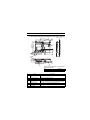
1
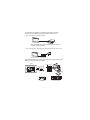
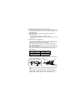
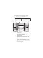
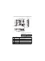
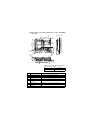
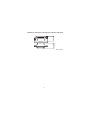
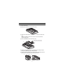
MITSUBISHI ELECTRIC
GOT 1000
Video/RGB Input Unit
User's Manual
GT15V-75V4R1
GT15V-75V4
GT15V-75R1
Art. no:
IB(NA)-0800348
01072007
Version C
MITSUBISHI ELECTRIC
INDUSTRIAL AUTOMATION
zSAFETY PRECAUTIONSz
(Always read these precautions before using this equipment.)
Before using this product, please read this manual and the relevant manuals
introduced in this manual carefully and pay full attention to safety to handle the
product correctly.
The precautions given in this manual are concerned with this product.
In this manual, the safety precautions are ranked as "DANGER" and "CAUTION".
DANGER
Indicates that incorrect handling may cause hazardous
conditions, resulting in death or severe injury.
CAUTION
Indicates that incorrect handling may cause hazardous
conditions, resulting in medium or slight personal
injury or physical damage.
Note that the
caution level may lead to a serious accident according to the
circumstances. Always follow the instructions of both levels because they are
important to personal safety.
Please save this manual to make it accessible when required and always forward
it to the end user.
A-1
[DESIGN PRECAUTIONS]
CAUTION
z Do not bundle the control and communication cables with main-circuit, power
or other wiring.
Run the above cables separately from such wiring and keep them a minimum
of 100mm (3.94in.) apart. Not doing so noise can cause a malfunction.
[MOUNTING PRECAUTIONS]
DANGER
z Be sure to shut off all phases of the external power supply used by the system
before mounting or removing this unit onto/from the GOT.
Not doing so can cause the unit to fail or malfunction.
CAUTION
z Use this unit in the environment that satisfies the general specifications
described in User’s Manual.
Not doing so can cause an electric shock, fire, malfunction or product damage
or deterioration.
z Tighten the mounting screws within the specified torque range.
Undertightening can cause the GOT to drop, short circuit or malfunction.
Overtightening can cause a drop, short circuit or malfunction due to the
damage of the screws or the GOT.
z Do not touch the conductive and electronic parts of the unit directly.
Doing so can cause a unit malfunction or failure.
A-2
[WIRING PRECAUTIONS]
DANGER
z Be sure to shut off all phases of the external power supply used by the system
before wiring.
Failure to do so may result in an electric shock, product damage or
malfunctions.
CAUTION
z Exercise care to avoid foreign matter such as chips and wire offcuts entering
the GOT. Not doing so can cause a fire, failure or malfunction.
z Make sure to securely connect the cable to the connector of unit.
Incorrect connection may cause malfunctions.
z Do not hold the cable by hand and pull it out from the unit.
When removing the cable from the unit, make sure to hold the connector by
hand and pull it.
Failure to do so may cause malfunctions or damage to the unit or cable.
z Solder the coaxial cable connector correctly.
Incomplete soldering may cause a malfunction.
A-3
[STARTUP/MAINTENANCE PRECAUTIONS]
DANGER
z When power is on, do not touch the terminals.
Doing so can cause an electric shock or malfunction.
z Before starting cleaning, always shut off GOT power externally in all phases.
Not doing so can cause a unit failure or malfunction.
Undertightening can cause a short circuit or malfunction.
Overtightening can cause a short circuit or malfunction due to the damage of
the screws or unit.
CAUTION
z Do not disassemble or modify the unit.
Doing so can cause a failure, malfunction, injury or fire.
z Do not drop the module or subject it to strong shock.
A module damage may result.
z Before touching the unit, always touch grounded metal, etc. to discharge static
electricity from human body, etc.
Not doing so can cause the unit to fail or malfunction.
[DISPOSAL PRECAUTIONS]
CAUTION
z When disposing of the product, handle it as industrial waste.
[TRANSPORTATION PRECAUTIONS]
CAUTION
z Make sure to transport the GOT main unit and/or relevant unit(s) in the
manner they will not be exposed to the impact exceeding the impact
resistance described in the general specifications of GT15 User’s manual, as
they are precision devices.
Failure to do so may cause the unit to fail.
Check if the unit operates correctly after transportation.
A-4
REVISIONS
* The manual number is noted at the lower right of the top cover.
Print Date
*Manual Number
Revision
Mar., 2006
IB(NA)-0800348-A First edition
Feb., 2007
IB(NA)-0800348-B
Partial addition
Chapter1, Section 2.4.1
Addition
Compliance with the EMC and Low
Voltage Directives
Jul., 2007
IB(NA)-0800348-C
Partial corrections
Compliance with the EMC and Low
Voltage Directives, Chapter 2, 3, 4
This manual confers no industrial property rights or any rights of any other kind,
nor does it confer any patent licenses. Mitsubishi Electric Corporation cannot be
held responsible for any problems involving industrial property rights which may
occur as a result of using the contents noted in this manual.
© 2006 MITSUBISHI ELECTRIC CORPORATION
A-5
CONTENTS
1. Overview ........................................................................................................ 1
2. Specifications ................................................................................................. 4
2.1 Video input unit specifications ................................................................. 4
2.2 RGB input unit specifications ................................................................... 5
2.3 Video/RGB input unit specifications ........................................................ 6
2.4 Cable specifications ................................................................................. 7
2.4.1 Specifications of the cables (coaxial cables) used when displaying
video images ................................................................................... 7
2.4.2 Specifications of the cables (9-core combined cables) used when
displaying RGB screens ................................................................ 10
3. Part Names and External Dimensions ......................................................... 11
3.1 Part names and external dimensions of the video input unit ................. 11
3.2 Part names and external dimensions of the RGB input unit .................. 12
3.3 Part names and external dimensions of the video/RGB input unit ........ 13
3.4 External dimensions of the extension interface relay board .................. 14
4. Installation Procedure .................................................................................. 15
A-6
Manuals
The following shows manuals relevant to this product.
Detailed Manual
Manual number
(Model code)
Manual name
GT15 User's Manual
(Sold separately)
SH-080528ENG
(1D7M23)
(Sold separately)
SH-080532ENG
(1D7M26)
GOT1000 Connection Manual
Relevant Manuals
For relevant manuals, refer to the PDF manual stored within the drawing
software used.
Packing List
The following items are included.
Model
Product
Video input unit
GT15V-75V4
GT15V-75R1
GT15V-75V4R1
Quantity
1
Mounting screw set (2 screws,2 stickers)
2
Extend interface relay board
1
RGB input unit
1
Mounting screw set (2 screws,2 stickers)
2
Extend interface relay board
1
Video/RGB input unit
1
Mounting screw set (2 screws,2 stickers)
2
Extend interface relay board
1
Compliance with the EMC and Low Voltage Directives
When incorporating the Mitsubishi GOT into other machinery or equipment and keeping
compliance with the EMC and low voltage directives, refer to "EMC AND LOW VOLTAGE
DIRECTIVE" of GT15 User's Manual.
The CE logo is printed on the rating plate of the GOT, indicating compliance with the EMC and
low voltage directives.
A-7
1. Overview
This User's Manual is related to the following units.
• MODEL GT15V-75V4 Video Input Unit (referred to as the Video Input Unit
hereinafter)
• MODEL GT15V-75R1 RGB Input Unit (referred to as the RGB Input Unit
hereinafter)
• MODEL GT15V-75V4R1 Video/RGB Input Unit (referred to as the Video/RGB
Input Module hereinafter).
When mounting the above units with the GT1585V-STBA, GT1575V-STBA
(referred to as GOT hereinafter), the images taken by video cameras or screens
on personal computers can be displayed on the GOT.
The video input unit can display the images taken by up to 4 video cameras on
the GOT.
GOT can be used as a vision sensor monitor.
Image data
Video camera*1
GOT
+
GT15V-75V4
Video camera
Camera power pack*2
Vision sensor (AS50VS or other)
*1: Power on the video camera simultaneously with the GOT.
*2: Power supply for the camera may be necessary depending on the
vision sensor to be used.
1
The RGB input unit can display a personal computer display on the GOT.
Video input is also available using an RGB output type vision sensor.
When connecting to a personal computer
*1
GOT+GT15V-75R1
*1: When connecting with a personal computer, ground wire of the
computer should be grounded.
When connecting to a video camera using an RGB output type vision sensor.
GOT+GT15V-75R1
RGB output type
vision sensor
For the video/RGB input unit, functions of both video input unit (GT15V-75V4) and
RGB input unit (GT15V-75R1) are available.
GOT*3
Video camera*2
GT15V-75V4R1
A 1254
B 348
注意 CAUTION
誤動 作の恐れあり
通電 中着脱しな いでくだ さい
Do n ot mou nt not desmou nt
a mo dule w hile th e powe r is
supp lied.
*1
Computer
2
PLCs for line control
*1: When connecting the unit to a personal computer, ground wire of the
computer should be grounded.
*2: Power on the video camera simultaneously with the GOT.
*3: Video images and personal computer screens cannot be displayed
on the GOT at the same time.
To use the Video input unit, RGB input unit and Video/RGB input unit, make the
Communication Settings.
For setting details, refer to GOT1000 Series Connection Manual.
For details of system configuration, refer to GOT1000 Series Connection
Manual.
For video input and RGB input functions, refer to the GT Designer2 Version
Screen Design Manual.
3
2. Specifications
2.1 Video input unit specifications
Item
Specifications
NTSC format, PAL format (interlaced format)
Video input Color
system
Monochrome EIA format, CCIR format (interlaced format)
Number of video input
channels
Video
Input signal
input
section
Display size [dot's]
4 channel
IVp-p, 75 , composite signal
640x480 (possible to reduce to 320x240, 160x120)
720x480 (possible to reduce to 360x240, 180x120) *1
Video external connection
Coaxial cable
method
Applicable wire size
75
coaxial shield cable
Maximum cable length
Refer to the specifications of the personal computer,
vision sensor and video camera to be used *2
Internal current consumption
(3.3VDC)
0.7A
Weight
0.2kg (0.44Ib)
*1: Compatible with PAL and CCIR formats only.
*2: The length of a cable differs depending on the specifications of the
vision sensor and video camera to be used.
Be sure to use the cable with specified length for the vision sensor
and video camera to be used.
4
2.2 RGB input unit specifications
Item
Specifications
RGB input method (dot's) Analog RGB(SVGA; 800x600, VGA; 640x480)
Number of video input
channels
Input image signal
RGB
Synchronizing signal
input
section
Display size [dot's]
RGB external connection
method
Applicable wire size
1 channel
1Vp-p, 75
TTL, 1k
800 600 (refresh rate 60, 72, 75 [Hz])
640 480 (refresh rate 60, 72, 75, 85 [Hz])
D-Sub15 pin
9-core combined cable (recommended)
Maximum cable length
Refer to the specifications of the personal computer,
vision sensor and video camera to be used *1
Internal current consumption
(3.3VDC)
0.91A
Weight
0.17kg (0.34Ib)
*1: The length of a cable differs depending on the specifications of the
personal computer and vision sensor to be used.
Be sure to use the cable with specified length for the personal
computer and vision sensor to be used.
5
2.3 Video/RGB input unit specifications
Item
Specifications
NTSC format, PAL format (interlaced format)
Video input Color
system
Monochrome EIA format, CCIR format (interlaced format)
Number of video input
channels
Video
Input signal
input
section
*3
Display size [dot's]
4 channel
IVp-p, 75 , composite signal
640x480 (possible to reduce to 320x240, 160x120)
720x480 (possible to reduce to 360x240, 180x120) *1
Video external connection
Coaxial cable
method
Applicable wire size
75
coaxial shield cable
RGB input method (dot's) Analog RGB(SVGA; 800x600, VGA; 640x480)
Number of video input
channels
Input image signal
RGB
Synchronizing signal
input
section
*3
Display size [dot's]
RGB external connection
method
Applicable wire size
1 channel
1Vp-p, 75
TTL, 1k
800 600 (refresh rate 60, 72, 75 [Hz])
640 480 (refresh rate 60, 72, 75, 85 [Hz])
D-Sub15 pin
9-core combined cable (recommended)
Maximum cable length
Refer to the specifications of the personal computer,
vision sensor and video camera to be used *2
Internal current consumption
(3.3VDC)
0.95A
Weight
0.21kg (0.42Ib)
*1: Compatible with PAL and CCIR formats only.
*2: The length of a cable differs depending on the specifications of the
personal computer, vision sensor and video camera to be used.
Be sure to use the cable with specified length for the personal
computer, vision sensor and video camera to be used.
*3: Both video images and RGB screens cannot be displayed on the
GOT at the same time.
6
2.4 Cable specifications
The following shows the cable specifications, connection diagram, and
connector used for the video input unit, RGB input unit, and video/RGB
input unit.
2.4.1 Specifications of the cables (coaxial cables) used
when displaying video images
(1) Coaxial cable
Use high frequency coaxial cable "3C-2V" or "5C-2V"
(conforms to JIS C 3501).
The following shows the coaxial cable specifications.
Item
3C-2V
5C-2V
Internal
condcuctive Insulating
Sheath
material
material
External
conductive
material
Construction
Cable diameter
5.4mm (0.21in)
7.4mm (0.29in)
Allowable bending
radius
22mm (0.87in) or more
30mm (41.18in) or more
Internal conductive
material diameter
0.5mm (0.02in)
(Annealed copper wire)
0.8mm (0.03in)
(Annealed copper wire)
Insulation material
diameter
3.1mm (0.12in) (Polyethylene)
4.9mm (0.19in) (Polyethylene)
External conductive
material diameter
3.8mm (0.15in) (Single annealed
copper wire mesh)
5.6mm (0.22in) (Single annealed
copper wire mesh)
Applicable connector
plug
Connector plug for 3C-2V (BNCP-3-N1-CAU is recommended.)
Connector plug for 5C-2V (BNCP-5-N1-CAU is recommended.)
(2) Connector
• GOT connector
Use BNC connector for GOT side connector.
The following shows the connection method for BNC connector
and coaxial cable.
7
(a) Construction of BNC connector and coaxial cable.
Parts of the BNC connector
Nut
Plug shell
Washer
Clamp
Construction of coaxial cable
Outer sheath
Outer conductor
Insulating material
Internal conductive material
Gasket
Contact
(b) Connecting the BNC connector with the coaxial cable.
1) Remove the outer sheath of the
coaxial cable in the specified
dimension as shown left.
15mm
(0.59inch)
Remove the outer sheath.
Clamp
2) Slip a nut, a washer, a gasket, and a
clamp through the coaxial cable as
shown left, and loosen the outer
conductor.
Nut
Washer
Gasket
Internal conductive
material
3mm
(0.12inch)
3) Cut off the insulating material and
internal conductive material in the
specified dimensions as shown left.
Cut off the outer conductor in the
same dimension as the taper part of
the clamp, and extend it over the
clamp.
Insulating material
6mm
(0.24inch)
Clamp and
outer conductor
4) Solder the contact to the tip of the
internal conductive material.
Soldering
5) Insert the contact assembly of 4) into
the plug shell, and engage the plug
shell with the nut.
8
*1: Soldered part must not have excess solder mound.
*2: The tail end of the contact must come into close contact with the cut
end of the insulating material. The contact must not be cutting in the
insulating material.
*3: Apply solder quickly so that the insulating material will not be
deformed by heat.
• Connector at the video camera and vision sensor
Use a connector applicable to the video camera or vision sensor
to be used.
(3) Precautions for cable preparation
The maximum cable length differs depending on the specifications of
the video camera and vision sensor to be used.
For details, refer to manuals for video camera and vision sensor.
When a cable length gets longer, video signals are attenuated, and
video images deteriorate.
When using a cable exceeding the length described in the following
table, it is recommended to correct video images using a video
signal amplifier.
Cable type
Cable length [m] (feet)
3C-2V
100 (328.1)
5C-2V
200 (656.2)
(4) Precautions for laying cable
Consider wiring using double-shielded coaxial cable in places that
are subject to large amounts of noise.
Double-shielded coaxial cable
Mitsubishi Cable ... 5C-2V-CCY
Enlarged view
of cable
Sheath
Sheath
Internal
conducter
Insulation External External
material conductor conductor
(Grounding)
Grounding
The 5C-2V connector plug is applicable to double-shielded coaxial
cable.
Connect the 5C-2V connector plug to the coaxial cable inside a
double-shielded coaxial cable. Ground the shielded part outside a
double-shielded coaxial cable as shown in the above figure.
9
2.4.2 Specifications of the cables (9-core combined
cables) used when displaying RGB screens
(1) Cable specifications
Item
Specifications
Applicable cable
Equivalent to SP23-23352A UL20276-SB
Applicable wire size
9-core combined cable (recommended)
(2) Connection diagram
Personal computer side
R
RGND
G
GGND
B
BGND
GND
GND
HSYNC
VSYNC
GND
NC
GND
SDA
SCL
75
1
6
2
7
3
8
5
10
13
14
4
9
11
12
15
Coaxical
Twisted pair
GOT side
1
6
2
7
3
8
5
10
13
14
4
9
11
12
15
R
RGND
G
GGND
B
BGND
DGND
DGND
HSYNC
VSYNC
NC
NC
NC
NC
NC
(3) Connector
• GOT side connector
The following model is used for the GOT connector.
Use a connector that matches the following connector.
15-pin D-sub (male) inch screw type
Manufactured by DDK
17HE-R13150-73MC2
• Connector at the personal computer and vision sensor
Use the connector applicable to the personal computer and
vision sensor.
(4) Precaution for cable creating
The length of a cable differs depending on the personal
computer and vision sensor to be used.
Male the create within the range of personal computer and
vision sensor specifications.
10
3. Part Names and External Dimensions
3.1 Part names and external dimensions of the video input unit
6)
GOT main unit
3
(0.12)
5)
98 (3.86)
7)
19.5
(0.77)
105 (4.13)
3)
133 (5.24)
6)
2.5
(0.10)
X
17.5 18
18
(0.69) (0.71) (0.71)
8.0
(0.32)
30.5
(1.20)
21.5
(0.85)
1)
34
(1.34)
4)
2)
Dimensions of X when the video input unit is
mounted to the GOT.
12.1”
18 (0.71)
10.4”
21 (0.83)
Unit: mm (inch)
No.
1)
Name
Connector for video
input
Description
Connector for connecting a coaxial cable
2)
Interface connector
Connector mounted to the GOT
3)
Extension connector
Connector to which a back extension unit is installed
4)
Connector for video/
RGB connection
Connector connecting with the video/RGB interface of GOT
5)
Board fixing screw
Screw for fixing the extend interface relay board
6)
Mounting screw
Mounting screws for fixing the unit to the GOT
7)
Rating plate
11
3.2 Part names and external dimensions of the RGB input unit
3)
6)
GOT main unit
3
(0.12)
5)
98 (3.86)
7)
8.0
(0.32)
105 (4.13)
133 (5.24)
6)
2.5
(0.10)
X
8.5
(0.33)
30.5
(1.20)
21.5
(0.85)
1)
113.5
(4.47)
4)
2)
Dimensions of X when the RGB input unit is
mounted to the GOT.
No.
1)
12.1”
18 (0.71)
10.4”
21 (0.83)
Unit: mm (inch)
Name
Connector for RGB
input
Description
Connector for connecting 9-core combined cables
2)
Interface connector
Connector mounted to the GOT
3)
Extension connector
Connector to which a back extension unit is installed
4)
Connector for video/
RGB connection
Connector connecting with the video/RGB interface of GOT
5)
Board fixing screw
Screw for fixing the extend interface relay board
6)
Mounting screw
Mounting screws for fixing the unit to the GOT
7)
Rating plate
-
12
3.3 Part names and external dimensions of the video/RGB
input unit
4)
7)
GOT main unit
3
(0.12)
6)
98 (3.86)
8)
8.0
(0.32)
19.5
(0.77)
105 (4.13)
133 (5.24)
7)
2.5
(0.10)
2)
X
17.5 18
18
(0.69) (0.71) (0.71)
34
26.0
(1.34)
(1.02)
8.0
(0.32)
8.5
(0.33)
30.5
(1.20)
21.5
(0.85)
1)
5)
3)
Dimensions of X when the video/RGB input
unit is mounted to the GOT.
12.1”
18 (0.71)
10.4”
21 (0.83)
Unit: mm (inch)
No.
Name
1)
Connector for video input
Connector for connecting a coaxial cable
Description
2)
Connector for RGB input
Connector for connecting 9-core combined cables
3)
Interface connector
Connector mounted to the GOT
4)
Extension connector
Connector to which a back extension unit is installed
5)
Connector for video/RGB
Connector connecting with the video/RGB interface of GOT
connection
6)
Board fixing screw
Screw for fixing the extend interface relay board
7)
Mounting screw
Mounting screws for fixing the unit to the GOT
8)
Rating plate
13
24 (0.94)
3.4 External dimensions of the extension interface relay board
27.5 (1.08)
64 (2.52)
Unit: mm (inch)
14
4. Installation Procedure
(1) Power off the GOT.
(2) Remove two extension unit covers of the GOT.
(3) Attach the extend interface relay board to the extend I/F-2 side on the
GOT.
After the installation, detach the connector cover from the extend
interface relay board.
(4) Fit the video/RGB input unit in the GOT case.
Remove the connector cover
4)
3)
(5) Fasten the video/RGB input unit by tightening its mounting screws (4
places) with tightening torgue 0.36 to 0.48 N•m.
(6) Fasten the bus connection unit by tightening the board fixing screws (2
places) with the tightening torque of 0.36 to 0.48 N•m.
5)
6)
15
(7) When installing an extension unit on the unit that has been installed,
remove the connector cover and the sticker.
When not installing an extension unit on the unit that has been installed,
in order to avoid receiving electrostatic, stick accessory stickers to cover
the top of mounting screws (4 places).
Keep the connector cover fixed.
Keep the sticker stuck as it is.
Connector cover
Accessory sticker
Sticker
Accessory sticker
Point
Remove the screws that fixes the extend interface relay board before
removing the unit.(Above 6))
16
MEMO
17
MITSUBISHI ELECTRIC
HEADQUARTERS
EUROPEAN REPRESENTATIVES
EUROPEAN REPRESENTATIVES
MITSUBISHI ELECTRIC EUROPE B.V.
EUROPE
German Branch
Gothaer Straße 8
D-40880 Ratingen
Phone: +49 (0)2102 / 486-0
Fax: +49 (0)2102 / 486-1120
MITSUBISHI ELECTRIC EUROPE B.V. CZECH REPUBLIC
Czech Branch
Radlická 714/113a
CZ-158 00 Praha 5
Phone: +420 (0)251 551 470
Fax: +420 (0)251-551-471
MITSUBISHI ELECTRIC EUROPE B.V.
FRANCE
French Branch
25, Boulevard des Bouvets
F-92741 Nanterre Cedex
Phone: +33 (0)1 / 55 68 55 68
Fax: +33 (0)1 / 55 68 57 57
MITSUBISHI ELECTRIC EUROPE B.V.
IRELAND
Irish Branch
Westgate Business Park, Ballymount
IRL-Dublin 24
Phone: +353 (0)1 4198800
Fax: +353 (0)1 4198890
MITSUBISHI ELECTRIC EUROPE B.V.
ITALY
Italian Branch
Viale Colleoni 7
I-20041 Agrate Brianza (MI)
Phone: +39 039 / 60 53 1
Fax: +39 039 / 60 53 312
MITSUBISHI ELECTRIC EUROPE B.V.
SPAIN
Spanish Branch
Carretera de Rubí 76-80
E-08190 Sant Cugat del Vallés (Barcelona)
Phone: 902 131121 // +34 935653131
Fax: +34 935891579
MITSUBISHI ELECTRIC EUROPE B.V.
UK
UK Branch
Travellers Lane
UK-Hatfield, Herts. AL10 8XB
Phone: +44 (0)1707 / 27 61 00
Fax: +44 (0)1707 / 27 86 95
MITSUBISHI ELECTRIC CORPORATION
JAPAN
Office Tower “Z” 14 F
8-12,1 chome, Harumi Chuo-Ku
Tokyo 104-6212
Phone: +81 3 622 160 60
Fax: +81 3 622 160 75
MITSUBISHI ELECTRIC AUTOMATION, Inc.
USA
500 Corporate Woods Parkway
Vernon Hills, IL 60061
Phone: +1 847 478 21 00
Fax: +1 847 478 22 53
GEVA
AUSTRIA
Wiener Straße 89
AT-2500 Baden
Phone: +43 (0)2252 / 85 55 20
Fax: +43 (0)2252 / 488 60
TEHNIKON
BELARUS
Oktyabrskaya 16/5, Off. 703-711
BY-220030 Minsk
Phone: +375 (0)17 / 210 46 26
Fax: +375 (0)17 / 210 46 26
Koning & Hartman b.v.
BELGIUM
Woluwelaan 31
BE-1800 Vilvoorde
Phone: +32 (0)2 / 257 02 40
Fax: +32 (0)2 / 257 02 49
INEA BH d.o.o.
BOSNIA AND HERZEGOVINA
Aleja Lipa 56
BA-71000 Sarajevo
Phone: +387 (0)33 / 921 164
Fax: +387 (0)33/ 524 539
AKHNATON
BULGARIA
4 Andrej Ljapchev Blvd. Pb 21
BG-1756 Sofia
Phone: +359 (0)2 / 817 6004
Fax: +359 (0)2 / 97 44 06 1
INEA CR d.o.o.
CROATIA
Losinjska 4 a
HR-10000 Zagreb
Phone: +385 (0)1 / 36 940 - 01/ -02/ -03
Fax: +385 (0)1 / 36 940 - 03
AutoCont C.S. s.r.o.
CZECH REPUBLIC
Technologická 374/6
CZ-708 00 Ostrava-Pustkovec
Phone: +420 595 691 150
Fax: +420 595 691 199
B:TECH A.S.
CZECH REPUBLIC
U Borové 69
CZ-58001 Havlíčkův Brod
Phone: +420 (0)569 777 777
Fax: +420 (0)569-777 778
Beijer Electronics A/S
DENMARK
Lykkegårdsvej 17, 1.
DK-4000 Roskilde
Phone: +45 (0)46/ 75 76 66
Fax: +45 (0)46 / 75 56 26
Beijer Electronics Eesti OÜ
ESTONIA
Pärnu mnt.160i
EE-11317 Tallinn
Phone: +372 (0)6 / 51 81 40
Fax: +372 (0)6 / 51 81 49
Beijer Electronics OY
FINLAND
Jaakonkatu 2
FIN-01620 Vantaa
Phone: +358 (0)207 / 463 500
Fax: +358 (0)207 / 463 501
UTECO A.B.E.E.
GREECE
5, Mavrogenous Str.
GR-18542 Piraeus
Phone: +30 211 / 1206 900
Fax: +30 211 / 1206 999
MELTRADE Ltd.
HUNGARY
Fertő utca 14.
HU-1107 Budapest
Phone: +36 (0)1 / 431-9726
Fax: +36 (0)1 / 431-9727
Beijer Electronics SIA
LATVIA
Vestienas iela 2
LV-1035 Riga
Phone: +371 (0)784 / 2280
Fax: +371 (0)784 / 2281
Beijer Electronics UAB
LITHUANIA
Savanoriu Pr. 187
LT-02300 Vilnius
Phone: +370 (0)5 / 232 3101
Fax: +370 (0)5 / 232 2980
INTEHSIS srl
MOLDOVA
bld. Traian 23/1
MD-2060 Kishinev
Phone: +373 (0)22 / 66 4242
Fax: +373 (0)22 / 66 4280
Koning & Hartman b.v.
NETHERLANDS
Haarlerbergweg 21-23
NL-1101 CH Amsterdam
Phone: +31 (0)20 / 587 76 00
Fax: +31 (0)20 / 587 76 05
Beijer Electronics AS
NORWAY
Postboks 487
NO-3002 Drammen
Phone: +47 (0)32 / 24 30 00
Fax: +47 (0)32 / 84 85 77
MPL Technology Sp. z o.o.
POLAND
Ul. Krakowska 50
PL-32-083 Balice
Phone: +48 (0)12 / 630 47 00
Fax: +48 (0)12 / 630 47 01
Sirius Trading & Services srl
ROMANIA
Aleea Lacul Morii Nr. 3
RO-060841 Bucuresti, Sector 6
Phone: +40 (0)21 / 430 40 06
Fax: +40 (0)21 / 430 40 02
Craft Con. & Engineering d.o.o.
SERBIA
Bulevar Svetog Cara Konstantina 80-86
SER-18106 Nis
Phone:+381 (0)18 / 292-24-4/5
Fax: +381 (0)18 / 292-24-4/5
INEA SR d.o.o.
SERBIA
Izletnicka 10
SER-113000 Smederevo
Phone: +381 (0)26 / 617 163
Fax: +381 (0)26 / 617 163
AutoCont Control s.r.o.
SLOVAKIA
Radlinského 47
SK-02601 Dolny Kubin
Phone: +421 (0)43 / 5868210
Fax: +421 (0)43 / 5868210
CS MTrade Slovensko, s.r.o.
SLOVAKIA
Vajanskeho 58
SK-92101 Piestany
Phone: +421 (0)33 / 7742 760
Fax: +421 (0)33 / 7735 144
INEA d.o.o.
SLOVENIA
Stegne 11
SI-1000 Ljubljana
Phone: +386 (0)1 / 513 8100
Fax: +386 (0)1 / 513 8170
Beijer Electronics AB
SWEDEN
Box 426
SE-20124 Malmö
Phone: +46 (0)40 / 35 86 00
Fax: +46 (0)40 / 35 86 02
Econotec AG
SWITZERLAND
Hinterdorfstr. 12
CH-8309 Nürensdorf
Phone: +41 (0)44 / 838 48 11
Fax: +41 (0)44 / 838 48 12
GTS
TURKEY
Darülaceze Cad. No. 43 KAT. 2
TR-34384 Okmeydanı-Istanbul
Phone: +90 (0)212 / 320 1640
Fax: +90 (0)212 / 320 1649
CSC Automation Ltd.
UKRAINE
15, M. Raskova St., Fl. 10, Office 1010
UA-02002 Kiev
Phone: +380 (0)44 / 494 33 55
Fax: +380 (0)44 / 494-33-66
MITSUBISHI
ELECTRIC
FACTORY AUTOMATION
EURASIAN REPRESENTATIVES
Kazpromautomatics Ltd.
Mustafina Str. 7/2
KAZ-470046 Karaganda
Phone: +7 7212 / 50 11 50
Fax: +7 7212 / 50 11 50
CONSYS
Promyshlennaya st. 42
RU-198099 St. Petersburg
Phone: +7 812 / 325 36 53
Fax: +7 812 / 325 36 53
ELECTROTECHNICAL SYSTEMS
Derbenevskaya st. 11A, Office 69
RU-115114 Moscow
Phone: +7 495 / 744 55 54
Fax: +7 495 / 744 55 54
ELEKTROSTILY
Rubzowskaja nab. 4-3, No. 8
RU-105082 Moscow
Phone: +7 495 / 545 3419
Fax: +7 495 / 545 3419
NPP "URALELEKTRA"
Sverdlova 11A
RU-620027 Ekaterinburg
Phone: +7 343 / 353 2745
Fax: +7 343 / 353 2461
KAZAKHSTAN
RUSSIA
RUSSIA
RUSSIA
RUSSIA
MIDDLE EAST REPRESENTATIVES
ILAN & GAVISH Ltd.
24 Shenkar St., Kiryat Arie
IL-49001 Petah-Tiqva
Phone: +972 (0)3 / 922 18 24
Fax: +972 (0)3 / 924 0761
ISRAEL
AFRICAN REPRESENTATIVE
CBI Ltd.
Private Bag 2016
ZA-1600 Isando
Phone: + 27 (0)11 / 928 2000
Fax: + 27 (0)11 / 392 2354
SOUTH AFRICA
Mitsubishi Electric Europe B.V. /// FA - European Business Group /// Gothaer Straße 8 /// D-40880 Ratingen /// Germany
Tel.: +49(0)2102-4860 /// Fax: +49(0)2102-4861120 /// [email protected] /// www.mitsubishi-automation.com