1
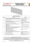
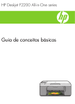
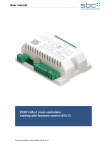
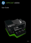
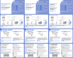
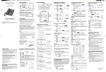
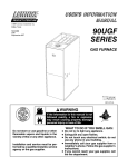
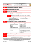
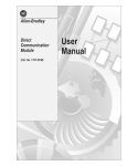
SLC 500 Remote I/O Adapter Module (Catalog Number 1747-ASB) Product Data Photo 92-599-1 Photo 92-599-2 (crop as shown) Photo 92-599-3 Support remote I/O communications across the full line of 1746 discrete and analog products. The 1747-ASB Remote I/O Adapter Module provides a communication link between SLC or PLC scanners and a wide variety of 1746 I/O modules. The 1747-ASB uses the time-tested Allen-Bradley RIO control link for remote I/O communications. This link allows for communication rates of up to 230.4K baud at 762 meters (2,500 feet) or for link distances to 3048 meters (10,000 feet) at 57.6K baud. Up to 32 different adapters can be configured on the RIO link using extended node capability. Monitor three 7-segment displays for quick status information and troubleshooting help. Each 1747-ASB module features a status display that provides alphanumeric status of the 1747-ASB module, the 1746 I/O that it controls, and communication with the RIO system. When combined with the COMM and FAULT LEDs, this display is a very effective diagnostic tool. Product Data SLC 500 Remote I/O Adapter Module Features and Benefits Supports 1/2-slot, 1-slot, and 2-slot addressing modes. Provides efficient image utilization by allowing you to assign the amount of image space required per slot for your particular I/O configuration. Provides switch selectable discrete or block transfer image mapping of speciality (e.g., analog) I/O modules. Selecting discrete mode provides deterministic data transfer and eliminates the need to program a command in your PLC, but potentially uses more image space. Block transfer mode conserves image space (1 byte of I/O image), but is not as deterministic and requires programming. The mode you select depends on your system requirements, specialty I/O module, and addressing mode. Secures I/O and DIP switch configurations in non-volatile memory. A special feature implemented with a DIP switch allows you to inhibit operation of the 1747-ASB module if the I/O configuration or DIP switch settings were modified since the last save. This can prevent system problems and save troubleshooting time. Uses the DIP switches to establish an expanded selection of operational settings and safeguards for the 1747-ASB module. The expanded selection of configuration settings available to you with the 1747-ASB module, including a processor restart lockout feature, discrete or block transfer mapping options, and selectable RIO image size, makes it easier to optimize system performance. Maximizes scanner image space using complementary I/O. If your scanner supports complementary I/O, this allows you to assign the same image location to inputs and outputs associated with different 1747-ASB modules, thereby saving addressable image space in the scanner data table for other I/O and compatible devices. What’s Inside... Hardware Overview System Overview System Operation Compatible Modules Allen-Bradley Support Specifications 2 Page 3 4 6 7 9 10 Product Data SLC 500 Remote I/O Adapter Module Hardware Overview Hardware features significant to installing, configuring, and troubleshooting the 1747-ASB module are described in the table and located in the following illustration. Hardware Features Hardware Function COMM LED Displays communication status FAULT LED Displays operating status Status Display Reveals status message data Door Label Provides module configuration and wiring information RIO Link and Processor Restart Lockout Connector Cable Tie Slots Provides physical connection to RIO link and processor restart lockout switch Secure and route wiring from module DIP Switches Establish configuration parameters for the module Test Plug Used for manufacturing purposes only Self-Locking Tabs Secure module in chassis slot COMM LED (Green) FAULT LED (Red) 2 3 4 5 6 7 8 FRN 3 4 6 8 Manufacturing Test Plug O N 6 5 7 8 RET O N 3 FAC 1M 1 RESP 2 HLS PRL 5 MADE IN USA ADDR MODE 6 4 SW3 LAST CHA SP MODE 7 KEY SA IMAGE SIZE (LSB) Î Î OPERATING TEMPERATURE CODE T3C RSV (MSB) 4 IN BAUD RATE PRI/COMP 3 NC SW2 LINE 2 2 SHLD 1 LINE 1 FOR HAZ. LOC. A196 CLASS 1, GROUPS A, B, C AND D, DIV. 2 7 Door Label UL 5 LOGICAL GROUP 8 IMPORTANT: SLC 500 INSTALL IN SLOT ZERO OF MODULAR CHASSIS ONLY REMOTE I/O ADAPTER MODULE CURRENT REQUIREMENT: 375mA SER LISTED IND. CONT. EQ. 1 2 3 4 5 6 7 8 2 SW1 LOGICAL RACK (LSB) RIO Link and Processor Restart Lockout Connector CAT O N 1 2 3 4 5 6 7 8 SERIAL NO. O N 1 (MSB) 1 Status Display O N STATUS SW1 COMM FAULT SW2 SW3 ADAPTER DIP Switches 1747–ASB Cable Tie Slots Self-Locking Tab 3 Product Data SLC 500 Remote I/O Adapter Module System Overview The 1747-ASB module is a single-slot, RIO communication link module. It occupies the first slot (slot 0) of a 1746 remote chassis, where the SLC processor normally resides. The 1747-ASB module is an adapter, or slave, on the RIO link and master of the remote chassis and remote expansion chassis where it resides. It can control up to 30 slots of I/O installed in up to three 1746 chassis. It acts as a gateway between a PLC or SLC system scanner and the I/O modules in the 1747-ASB remote chassis and remote expansion chassis. Output data is sent from the system scanner to the 1747-ASB module across the RIO link. It is automatically transferred to the output modules across the chassis backplane. Inputs from the input modules are collected across the backplane by the 1747-ASB module and sent back to the scanner across the RIO link. No user programming of the 1747-ASB module is necessary. Typical PLC to 1747-ASB Configuration In this illustration the PLCs built-in scanner controls two 1747-ASB modules. 1747-ASB #1 controls one 7-slot and one 10-slot 1746 chassis, and 1747-ASB #2 controls one 4-slot, one 7-slot, and one 13-slot 1746 chassis. A single 1747-ASB module can control up to three 1746 chassis or 30 slots. Scanner Adapter PLC 1747-ASB #1 1747-ASB #2 I/O Modules Controls up to 16 compatible I/O modules Controls up to 23 compatible I/O modules 1747-ASB #1 PLC Processor/Scanner PLC Local Chassis 7-slot Remote Chassis 10-slot Remote Expansion Chassis RIO Link PanelView Operator Terminal 1747-ASB #2 1747-ASB modules are serially connected in a daisy-chain configuration using Belden 9463 cable. 4 4-slot Remote 7-slot Remote Expansion Chassis Chassis RediPANEL 13-slot Remote Expansion Chassis Product Data SLC 500 Remote I/O Adapter Module Typical SLC to 1747-ASB Configuration In this illustration the 1747-SN RIO scanner resides in the second slot (slot 1) of the local chassis and controls three 1747-ASB modules. 1747-ASB #1 controls one 4-slot and one 10-slot chassis. 1747-ASB #2 controls one 13-slot chassis. 1747-ASB #3 controls one 7-slot and one 13-slot chassis. Scanner Adapter SLC 1747-ASB #1 1747-ASB #2 1747-ASB #3 I/O Modules controls up to 13 compatible I/O modules controls up to 12 compatible I/O modules controls up to 19 compatible I/O modules 1747-ASB #1 SLC Processor Scanner (1747-SN) SLC Local Chassis 4-slot Remote 10-slot Remote Expansion Chassis Chassis PanelView Operator Terminal RIO Link 13-slot Remote Chassis 1747-ASB #2 1747-ASB modules are serially connected in a daisy-chain configuration using Belden 9463 cable. 7-slot Remote Chassis 13-slot Remote Expansion Chassis 1747-ASB #3 5 Product Data SLC 500 Remote I/O Adapter Module System Operation When power is applied to the 1747-ASB it automatically determines which I/O modules you installed in its chassis and configures its own image table according to the DIP switch settings you set before installation. If a valid configuration has been set, operation will begin. You make selections for starting logical rack, starting logical group, image size, and slot addressing mode. For example, slot addressing refers to how each chassis slot is assigned a specific amount of the 1747-ASB I/O image. The amount depends on which addressing mode you choose: 1/2-slot, 1-slot, or 2-slot addressing. Typical uses of the different modes are shown in the following table. Addressing Mode Typically used with these modules: 1-Slot Addressing 4, 8, or 16 point discrete I/O modules; specialty I/O modules 2-Slot Addressing 4 or 8 point discrete I/O modules; specialty I/O modules 1/2-Slot Addressing 4, 8, 16, or 32 point discrete I/O modules; specialty I/O modules Scanner Serial RIO Link • • 1747-ASB Chassis Resident I/O 1747-ASB Built-in (PLC) Modular (PLC or SLC) Parallel Backplane Bus • • Discrete Mode Block Transfer Mode • • • Discrete I/O Modules Analog I/O Modules Other Specialty I/O Modules Inputs from I/O resident in the 1747-ASB chassis are gathered by the 1747-ASB module in a single SLC backplane input scan. These inputs are then transmitted from the 1747-ASB to the scanner on the RIO link using RIO discrete transfers and/or RIO block transfers. Outputs intended for I/O modules resident in the 1747-ASB chassis are sent by the scanner on the RIO link to the 1747-ASB using RIO discrete transfers and/or RIO block transfers. These outputs are then transmitted to the appropriate I/O module in a single SLC backplane scan. RIO discrete transfers are transparent to a user. RIO block transfers are initiated by instructions added to the PLC ladder logic program. RIO block transfers are used when large amounts of data must be exchanged. 6 Product Data SLC 500 Remote I/O Adapter Module Compatible Modules RIO Scanners The 1747-ASB module is compatible with all Allen-Bradley scanners. Scanners that do not support RIO block transfers do not work with all of the I/O modules supported by the 1747-ASB module. For example, the 1747-SN Series A, RIO Scanner, does not work with the 1746-BAS, BASIC Module, since the scanner does not support RIO block transfers. Refer to the appropriate scanner manual for details concerning physical and logical specifications. Compatible Scanners Catalog Number Device Extended Node Capability Comments 1771-SN Sub I/O Scanner for Mini-PLC-2 and PLC-5 families 1772-SD, -SD2 Remote Scanner/Distribution Panel for PLC-2 family Yes (except with SD-2 Series A) 1775-S4A, -S4B, -S5 I/O Scanner Programmer Interface Module for PLC-3 family Only available with S5 scanner – 1775-SR, -SR5 Remote Scanner Distribution Panel for PLC-3/10 family Only available with SR5 scanner – 1785-L11B PLC-5/11 (in scanner mode) Yes – 1785-LT/x PLC-5/15 (in scanner mode) Yes PLC-5/15 Series B Revision H or later have partial rack addressing. Earlier versions are limited to 3 logical devices. 1785-L20B PLC-5/20 (in scanner mode) Yes – 1785-LT2 PLC-5/25 (in scanner mode) Yes PLC-5/25 Series A Revision D or later have partial rack addressing. Earlier versions are limited to 7 logical devices. 1785-L30x PLC-5/30 (in scanner mode) Yes – 1785-L40x PLC-5/40 (in scanner mode) Yes – 1785-L60x PLC-5/60 (in scanner mode) Yes – 5250-RS Remote Scanner for PLC-5/250 Yes – 1747-SN SLC Remote I/O Scanner Yes Series A scanner does not have block transfer capability. 6008-SI IBM PC I/O Scanner Module Yes – 6008-SV VMEbus I/O Scanner Module Yes – Q-bus I/O Scanner Module No – 6008-SQH1, -SQH2 No Revision D or later SD-2 scanner must be Revision 3 or later. 7 Product Data SLC 500 Remote I/O Adapter Module RIO Adapters The 1747-ASB Module can physically reside on the RIO link with any other adapter. The following table lists the adapters available for use with a RIO link. Compatible RIO Adapters Catalog Number 8 Device Extended Node Capability Comments 1785-LT/x PLC-5/15 Yes In adapter mode 1785-LT2 PLC-5/25 Yes In adapter mode 1785-LT3 PLC-5/12 Yes In adapter mode 1785-L30x PLC-5/30 Yes In adapter mode 1785-L40x PLC-5/40 Yes In adapter mode 1785-L60x PLC-5/60 Yes In adapter mode 1771-ASC Remote I/O Adapter Module No – 1771-ASB Remote I/O Adapter Module Series B and C only 1771-AM1 1-Slot I/O Chassis with Integral Power Supply and Adapter Yes – 1771-AM2 2-Slot I/O Chassis with Integral Power Supply and Adapter Yes – 1784-F30D Plant Floor Terminal Remote I/O Expansion Module Yes – 1771-RIO Remote I/O Interface Module No – 1771-JAB Single Point I/O Adapter Module Yes – 1771-DCM Direct Communication Module No – 1778-ASB Remote I/O Adapter Module Yes – 1747-DCM Direct Communication Module Yes – 2706-xxxx DL40 Dataliner Yes 2705-xxx RediPANEL Yes – 2711-xx PanelView Terminal Yes – 1336-RIO Remote I/O Adapter for 1336 AC Industrial Drives Yes – 1395-NA Remote I/O Adapter for 1395 DC Industrial Drives Yes – 1747-ASB SLC 500 Remote I/O Adapter Module Yes – Series A, B, and C Must be catalog number 2706-ExxxxxB1. Product Data SLC 500 Remote I/O Adapter Module I/O Modules The following modules can be placed in the 1747-ASB chassis: Compatible I/O Modules ➀ Catalog Number Device Comments 1746-xxx All discrete I/O modules – 1746-Nxx All analog I/O modules – 1746-BAS BASIC Module 1746-HS IMC 110 Motion Control Module 1747-KE RS-232/DH-485 Communication Interface Module 1747-DSN Distributed I/O Scanner 1747-DCM Direct Communication Module – 1746-NT4 Thermocouple/mV Input Module – 1746-NR4 RTD/Resistance Module – SLC 5/01 mode – 1 word input, 0 words output SLC 5/01 mode ➀ The 1746-HSCE High-Speed Counter module is not compatible in a 1747-ASB remote configuration. Allen-Bradley Support In today’s competitive environment, when you buy any product, you expect that product to meet your needs. You also expect the manufacturer of that product to back it up with the kind of customer service and product support that will prove you made a wise purchase. As the people who design, engineer, and manufacture your Industrial Automation Control equipment, Allen-Bradley has a vested interest in your complete satisfaction with our products and services. Allen-Bradley offers support services worldwide, with over 75 Sales/Support Offices, 512 authorized Distributors and 260 authorized Systems Integrators located throughout the United States alone, plus Allen-Bradley representatives in every major country in the world. Contact your local Allen-Bradley representative for: • sales and order support • product technical training • warranty support • support service agreements 9 Product Data SLC 500 Remote I/O Adapter Module Specifications Specification Description Backplane Current Consumption 375 mA at 5V Operating Temperature 32°F to 140°F (0°C to 60°C) Storage Temperature –40°F to +185°F (–40°C to +85°C) Humidity 5% to 95% noncondensing Noise Immunity NEMA standard ICS 2-230 Agency Certification (when product or packaging is marked) •CSA certified •CSA Class I, Division 2 Groups A, B, C, D certified •UL listed •CE marked for all applicable directives Baud Rate Determination of Maximum Cable Length and Terminating Resistor Size Baud Rate U Using Extended N Node Capability N Using U Not Extended Node Capability N 57.6K baud 115.2K baud 230.4K baud 57.6K baud 115.2K baud 230.4K baud Maximum Cable Distance (Belden 9463) 3048 meters (10,000 feet) 1524 meters (5,000 feet) 762 meters (2,500 feet) 3048 meters (10,000 feet) 1524 meters (5,000 feet) 762 meters (2,500 feet) Resistor Size 82Ω 1/2 Watt 1 Ω 11/22 Watt W 150Ω 82Ω 1/2 Watt Performance The 1747-ASB (Remote I/O) performance is determined by I/O module configuration (i.e., number and type of modules in chassis) and by remote system configuration (i.e., baud rate, number of 1747-ASB modules, PLC/Scanner, etc.). Refer to the Remote I/O Adapter Module User Manual, publication 1747-6.13, for more information. 10 Product Data SLC 500 Remote I/O Adapter Module Notes 11 3/& 3/& 3/& DQG 3/& DUH UHJLVWHUHG WUDGHPDUNV RI WKH $OOHQ%UDGOH\ &RPSDQ\ ,QF 6/& 6/& 3/& 3/& 3/& 3/& 3/& 3/& 3/& 3/& 3/& 'DWDOLQHU ,0& 3DQHO9LHZ DQG 5HGL3$1(/ DUH WUDGHPDUNV RI $OOHQ%UDGOH\ &RPSDQ\ ,QF ,%0 LV D UHJLVWHUHG WUDGHPDUN RI ,QWHUQDWLRQDO %XVLQHVV 0DFKLQHV ,QFRUSRUDWHG $OOHQ%UDGOH\ D 5RFNZHOO $XWRPDWLRQ %XVLQHVV KDV EHHQ KHOSLQJ LWV FXVWRPHUV LPSURYH SURGXFWLYLW\ DQG TXDOLW\ IRU PRUH WKDQ \HDUV :H GHVLJQ PDQXIDFWXUH DQG VXSSRUW D EURDG UDQJH RI DXWRPDWLRQ SURGXFWV ZRUOGZLGH 7KH\ LQFOXGH ORJLF SURFHVVRUV SRZHU DQG PRWLRQ FRQWURO GHYLFHV RSHUDWRU LQWHUIDFHV VHQVRUV DQG D YDULHW\ RI VRIWZDUH 5RFNZHOO LV RQH RI WKH ZRUOG·V OHDGLQJ WHFKQRORJ\ FRPSDQLHV :RUOGZLGH UHSUHVHQWDWLRQ $XVWUDOLD $XVWULD %DKUDLQ %HOJLXP %UD]LO %XOJDULD &DQDGD &KLOH &KLQD 35& &RORPELD &RVWD 5LFD &URDWLD &\SUXV &]HFK 5HSXEOLF (FXDGRU (J\SW (O 6DOYDGRU )LQODQG )UDQFH *HUPDQ\ *UHHFH *XDWHPDOD +RQGXUDV +RQJ .RQJ +XQJDU\ ,FHODQG ,QGLD ,QGRQHVLD ,UHODQG ,VUDHO ,WDO\ -DPDLFD -DSDQ -RUGDQ .RUHD .XZDLW /HEDQRQ 0DOD\VLD 0H[LFR 1HWKHUODQGV 1HZ =HDODQG 1RUZD\ 3DNLVWDQ 3HUX 3KLOLSSLQHV 3RODQG 3RUWXJDO 3XHUWR 5LFR 4DWDU 5RPDQLD 5XVVLD&,6 6DXGL $UDELD 6LQJDSRUH 6ORYDNLD 6ORYHQLD 6RXWK $IULFD 5HSXEOLF 6SDLQ 6ZHGHQ 6ZLW]HUODQG 7DLZDQ 7KDLODQG 7XUNH\ 8QLWHG $UDE (PLUDWHV 8QLWHG .LQJGRP 8QLWHG 6WDWHV 8UXJXD\ 9HQH]XHOD <XJRVODYLD $UJHQWLQD 'HQPDUN $OOHQ%UDGOH\ +HDGTXDUWHUV 6RXWK 6HFRQG 6WUHHW 0LOZDXNHH :, 86$ 7HO )D[ 3XEOLFDWLRQ $SULO 3XEOLFDWLRQ $SULO 6XSHUVHGHV 3XEOLFDWLRQ 'HFHPEHU &RS\ULJKW $OOHQ%UDGOH\ &RPSDQ\ ,QF 3ULQWHG LQ 86$