1
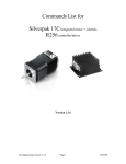
Commands List for SilverPak 23C Integrated motor + control/drive SilverPak 23CE Integrated motor + control/drive + encoder R356 Stand Alone control/drive + encoder Version 1.12 RMS Technologies Version 1.12 Page 1 9/28/2014 Thank you for purchasing the SILVERPAKC23 integrated motor and controller/driver with optional encoder feedback (SILVERPAKCE23), or the R356 stand alone controller/driver with encoder feedback product. This product is warranted to be free of manufacturing defects for one year from the date of purchase. Technical Support for RMS Technologies By Telephone: 877-301-3609 (Mon.-Fri., 8:00 a.m.-5:00 p.m.) On the Web: www.rmsmotion.com Our technical support group is glad to work with you in answering your questions. If you cannot find the solution to your particular application, or, if for any reason you need additional technical assistance, please call technical support at 877-301-3609. PLEASE READ BEFORE USING Before you begin, ensure there is a suitable DC Power Supply. Do not disconnect the DB-15 cable while power is still being applied to the controller. This will damage the board. The minimum voltage for the controller is 12.0 volts. Under any circumstances, do not exceed +40 VDC. DISCLAIMER The information provided in this document is believed to be reliable. However, no responsibility is assumed for any possible inaccuracies or omissions. Specifications are subject to change without notice. RMS Technologies reserves the right to make changes without further notice to any products herein to improve reliability, function, or design. RMS Technologies does not assume any liability arising out of the application or use of any product or circuit described herein; neither does it convey any license under its patent rights, nor the rights of others. There are known issues involving the Halt command (i.e., H01) when stored in memory location zero. Upon power up, the remaining command string after the Halt command might be executed if the user types in a new command. If memory location zero is not being used, the user is advised to always clear everything in memory by typing /1?9. Otherwise, the user may terminate the remaining command string in the buffer by issuing a /1T. Special Symbols Indicates a WARNING and that this information could prevent injury, loss of property, or even death (in extreme cases). RMS Technologies Version 1.12 Page 2 9/28/2014 SilverPakC23/SilverPakCE23 and R356 Commands User Manual Product: Version: Date: SILVERPAKC23/SILVERPAKCE23; R356 1.12 9/28/2014 Version History Version Date Description of Changes 1.00 New User Manual 1.01 Corrected m to be 3.0Amps not 2.0Amps Added extra note about step & direction mode Removed c command 1.02 1.03 1.04 1.05 1.06 2/28/2007 1.07 4/13/2007 1.08 07/17/2007 1.09 7/01/2008 1.10 8/17/2009 1.11 9/28/2014 RMS Technologies Version 1.12 Page 3 Updated pinouts, updated encoder info, o command range, updated wording of Z command. Added example for Opto and Jog Mode and added B command Standardization of manuals Velocity range, explanation of commands more in detail Updated response codes Added R356 details; Updated Appendix 2 Updated Z command max value, n1 mode “B” command, and Appendix 1 for encoder use. Updated Appendix 2: step/dir info. 9/28/2014 TABLE OF CONTENTS DT Protocol syntax 5 Running two or more motors together 5 Default Values 5 List of Commands 6 HOMING & POSITIONING 6 VELOCITY & ACCELERATION 6 SETTING CURRENT 7 LOOPING & BRANCHING 7 POSITION CORRECTION – ENCODER OPTION ONLY 9 PROGRAM STORAGE & RECALL 9 PROGRAM EXECUTION 9 MICROSTEPPING 9 BAUD CONTROL 10 Responses from Controller Error! Bookmark not defined. Understanding Response 12 Homing Sensor 14 APPENDIX 1 15 Encoder Usage 15 Position Correction Mode 15 Overload Report Mode 16 APPENDIX 2 16 STEP AND DRIVE MODE 16 RMS Technologies Version 1.12 Page 4 9/28/2014 DT Protocol syntax The DT Protocol allows the unit to be commanded over a simple serial port. Start Address Commands Run End of a string Character / 1-9* Command strings R <CR> *To Access Drivers 10 – 16 Driver # Command A : B ; C < D = E > F ? 0 @ use the following: (colon) (semi colon) (less than) (equals) (greater than) (question mark) (at sign) Running two or more motors together Motors Motors Motors Motors Motors Motors Motors Motors Motors Motors Motors Motors 1 and 2: 3 and 4: 5 and 6: 7 and 8: 9 and 10: 11 and 12: 13 and 14: 15 and 16: 1, 2, 3 and 4: 5, 6, 7 and 8: 9, 10, 11 and 12: 13, 14, 15 and 16: For all motors: “A” “C” “E” “G” “I” “K” “M” “O” “Q” “U” “Y” “]” (close bracket) “_” (underscore) Example: /CA5000R will move motors 3 and 4 to Absolute Position 5000. Default Values Function (command) Running Current (m) Holding Current (h) Step Resolution (j) Top Velocity (V) Acceleration (L) Position Microstep smoothness (o) Outputs (J) Baud Rate RMS Technologies Version 1.12 Description 25% of 3.0 Amps (0.75 Amps) 10% of max current (0.30 Amps) 256x 305175 PPS (microsteps/sec) L = 1000, 6103500 μsteps/sec2 0 1500 Both are turned off, inputs 1 & 2 9600 bps Page 5 9/28/2014 List of Commands Operand Command (Case Sensitive) Example HOMING & POSITIONING Z 0-max* /1Z10000R z 0-max* /1z65536R A 0-max* /1A10000R 0 or 1 /1f1R P 0-max* /1P10000R D 0-max* /1D10000R B 0-max* /1B1000R 0, 1 /1TR /1F1R f Description Home & Initialize the motor. Motor will turn towards 0 until the home opto sensor is interrupted. If already interrupted it will back out of the opto and come back in until re-interrupted. Current motor position is set to zero. Speed of homing is set by V. In the example, the motor will take 10000 steps to find the home sensor. If sensor is still not found after 10000 steps, it will stop motion. Only opto #1 (pin 7) can be used with this. Sets current position without moving motor. Works accurately when new position is divisible by 1024. Move Motor to Absolute position. i.e. moves to the 10,000th step. Issuing A10000 again will NOT move the motor because it is already at that value. Sets polarity of direction of home sensor, default is 0. Move Motor relative number of steps in positive direction. A “P0” command rotates motor infinitely, which enters into Velocity Mode. Any other finite number will set the mode to be in Position Mode. Move Motor relative number of steps in negative direction (Note: Motor will not run in the negative direction if the position is at 0. You can use the ‘z’ command to set the 0 position to be further away in the negative direction. OR you can use the F command (F1) prior to the P command to reverse direction of rotation.) A “D0” command rotates motor infinitely, which enters into Velocity Mode. Any other finite number will set the mode to be in Position Mode. Sets the distance for pulse jog mode (see n command) T F * 2^31 - 1 VELOCITY & ACCELERATION V 0-2^31 /1V2000R L 0-65000 /1L5000R RMS Technologies Version 1.12 Terminate current command Reverses the positive direction to be negative. The P and D command will switch directions. Default is 0. Max value is (2^31)-1 = 2,147,483,647 In Position Mode, this sets the Top Speed of the Motor in µsteps/sec. During velocity mode, speed can be changed on the fly (during rotation). This sets the Acceleration factor µsteps/sec² = (L Value) x (6103.5). i.e. /1L1R takes 16.384 Seconds to get to a speed of V=100000 (µsteps/sec) Default is L=1000, default speed V = 305175 µsteps/sec, so default acceleration = 6103500 μsteps/sec2. It should take 0.05 seconds to get to top speed. Page 6 9/28/2014 Command (Case Sensitive) Operand SETTING CURRENT m 0-100 h 0-50 Example Description /1m50R Sets the running current on a scale of 0 to 100% of the max current, 3.0A. Default setting is m25. Sets the Hold Current on a scale of 0 to 50% of the max current, 3.0 Amps. Default setting is h10. /1h20R LOOPING & BRANCHING g /1gP10G5R G 0-30000 /1gP10G0R M H 0-30000 01 11 02 12 03 13 04 14 /1M2000R /1gH02P100 00G20R Beginning of a repeat loop End of a repeat loop. Loops can be nested up to 4 levels. A value of 0 causes the loop to be infinite. Delay for “M” milliseconds Halt the current command string and wait until condition specified. The example will wait for switch two (2) to close (0) and then proceed to execute “P10000”. 01 11 02 12 03 13 04 14 S 01 11 02 12 03 13 04 14 /1gS02A1000 0A0G20R Wait Wait Wait Wait Wait Wait Wait Wait for for for for for for for for low on input 1 (Pin 13) high on input 1 (Pin 13) low on input 2 (Pin 5) high on input 2 (Pin 5) low on input 3 (Pin 7) high on input 3 (Pin 7) low on input 4 (Pin 14) high on input 4 (Pin 14) Halted operation can also be resumed by typing /1R If it is desired to stop motion rather than to wait for the input and move, one can use input 2 (pin 5) to stop motion of a P0 or D0 command. /1P0R and close input 2 to ground to stop motion. Skip command: will skip the command following it if the input is high or low. Useful for executing different programs based on a high or low signal on an input. 01 11 02 12 03 13 04 14 Skip Skip Skip Skip Skip Skip Skip Skip next next next next next next next next instruction instruction instruction instruction instruction instruction instruction instruction if if if if if if if if low on input 1 (Pin 13) hi on input 1 (Pin 13) low on input 2 (Pin 5) hi on input 2 (Pin 5) low on input 3 (Pin 7) hi on input 3 (Pin 7) low on input 4 (Pin 14) hi on input 4 (Pin 14) Can be used to escape loops by going to other stored programs RMS Technologies Version 1.12 Page 7 9/28/2014 Command (Case Sensitive) n Operand 0-4095 Example Description /1n2R Sets Modes – Interpret as combination of Binary Bits Bit0: /1n1R Enable Pulse Jog Mode. Jog distance is given by “B” command. Velocity is given by “V” command. The Switch Inputs 1 and 2 become the Jog Inputs. Press input 1 to rotate CW for a given distance, B. Press input 2 to rotate CCW for a given distance, B. If also in position correction mode, “B” will be in microsteps and not encoder counts. Bit1: /1n2R Enable Limit. The opto input #3, pin 7, becomes one limit switch for rotating CW (using P command). The opto input #4, pin 14, becomes the other limit switch for rotating CCW (using D command). Use /1P0R to rotate towards the limit switch. Can be combined with other commands like: /1P0P500R: rotate continuously until input 3 is low, then move 500 more steps. Bit2: /1n4R Enable Continuous Jog Mode. Continuous run of motor while switch is depressed. Velocity is given by the “V” command. Note that the jog mode allows moves below zero, which will be interpreted by any subsequent “A” command as a large positive number. If this is undesirable, please use the “z” command to define zero position to be some positive number so that underflow will not occur. Bit3 : /1n8R Enables Position Correction Mode. See Appendix 1 Bit4 : /1n16R Enabled Overload Report Mode. See Appendix 1 Bit5 : /1n32R Enable Step And Direction Mode A value of 1 for this mode, or enable Dual Encoder Mode if value of 0. i.e. /1n96<CR> (96=32+64) Enables step and dir mode and slaves the motor to it. (See Appendix 2) Bit6 : /1n64R Enable Motor slave to encoder/step-dir. Note: /1n10R will enable limit (n2) and the position correction mode (n8). Or, /1n9R will be jog mode (n1) and position correction mode (n8). RMS Technologies Version 1.12 Page 8 9/28/2014 Command (Case Sensitive) Operand Example Description POSITION CORRECTION – ENCODER OPTION ONLY N 1-2 /1N1R Special Modes: 1 = Encoder with no index (default). Motor will home to the opto sensor #1, pin 7. 2 = Encoder with index. Homes to the index. aC 1-65000 /1aC100R When in position correction mode, set distance allowed to move before the motor corrects using encoder feedback. See Appendix 1 aE 1000-10^6 /1aE12500R Set Encoder ratio. This sets the ratio between the encoder ticks/rev and the microsteps/rev for the motor. See Appendix 1 au 1-10^6 /1au10000R Set Overload Timeout. This sets the number of times the move is retried in case a move stalls. See Appendix 1 r /1rR This will recover the encoder after there has been a timeout due to an overload timeout on the encoder (See Appendix 1) PROGRAM STORAGE & RECALL s 0-15 /1s1A10000A Stores a program. Program 0 is executed on power 0R up (Total of 14 commands max per string when storing, but if not storing you can send 256 characters max). e 0-15 /1e1R Executes the Stored Programs 0-15. You can execute one program within a program. i.e. /1s0V500j2e1R, and /1s1gP1000M500G5e2R and /1s2f1Z100000R: This example will power on, execute speed of 500, 2x microstep and execute program #1: move 1000 steps and pause 0.5 seconds (5 times), then execute program 2 which will home the motor in the opposite direction. PROGRAM EXECUTION R /1R X MICROSTEPPING j 2, 4, 8, 16, 32, 64, 128, 256 o 1400-1650 (default 1500) /1j256R RMS Technologies Version 1.12 Run the command string that is currently in the execution buffer – Always end commands with ‘R’. Repeat the current command string Adjusts the resolution in micro-steps per step. Allows user to correct any unevenness in microstep size. Adjusts audible noise and should be executed while motor is running. Should only be adjusted in small increments and should not exceed 1650 and should not be set below 1400. Page 9 9/28/2014 Command (Case Sensitive) Operand Example ON/OFF DRIVERS (OUTPUTS) J 0-3 Description On/Off Driver. Turns on or off the two outputs. (I/O’s are bidirectional) It’s a two bit Binary value: 3=11=Both Drivers On, 2=10=Driver2 on, Driver1 off, etc. (Drivers output 3VDC max) Driver1 (Pin 10) Driver2 (Pin 2) QUERY COMMANDS The following commands are queries and cannot be cascaded in strings or stored. They can be executed while other commands are still running. ? 0 /1?0 Returns the current motor position ? 1 /1?1 Returns the current Start Velocity ? 2 /1?2 Returns the current Slew Speed for Position mode ? 3 /1?3 Returns the current Stop Speed ? 4 /1?4 Returns the status of all four inputs, 0-15 representing a 4 bit binary pattern: Bit 0 = Input 1 (Pin 13) Bit 1 = Input 2 (Pin 5) Bit 2 = Input 3 (Pin7) Bit 3 = Input 4 (Pin 14) ? 5 /1?5 Returns the current Velocity mode speed ? 6 /1?6 Returns the current step size ? 7 /1?7 Returns the current ‘o’ value ? 8 /1?8 Returns the Encoder Position (can be zeroed by “z” command) ? 9 /1?9 Erases all commands/program stored in EPROM except for the any settings such as current, microstepping, velocity, acceleration and any other settings $ /1$ & Q /1& /1Q T p /1T /1p66 Recalls current command executed. To see what currently stored in a specific program, run the program and issue the /1$ example: /1e2R /1$ Returns the current Firmware revision and date Query current status of the controller: 0 = No Error 1 = Initialization error 2 = Bad Command 3 = Operand out of range Terminate current commands Sends out the number 66 or any number placed after p, mostly used for confirmation of when a move is done. For example /1P1000p66R will send out the number 66 when the motor has moved 1000 steps. (Any number can be used after p). BAUD CONTROL b 9600 19200 38400 /1b19200R RMS Technologies Version 1.12 Adjustable baud rate This command will usually be stored as program zero and execute on power up. Default baud rate is 9600. Page 10 9/28/2014 Responses from Controller The SILVERPAKC23 and R356 respond to commands by sending messages addressed to the Master Device (in most cases is your PC). It always assumes it has an address of zero (0). The master device should parse the communications on the bus continuously for responses starting with /0. (It is not recommended, for example, to look for the next character coming back after issuing a command because glitches on the bus when the bus reverses direction can sometimes be interpreted as characters). After the /0 the next is the “status character” which is a collection of 8 bits. These bits are: Bit 7 Reserved Bit 6 Always set Bit 5 Ready Bit – it is set when the unit is ready to accept a command Bit 4 Reserved Bit 3, 2, 1, 0 represent the error codes: 0 1 2 3 4 5 6 7 8 9 10 11 12 13 14 15 ‘ A B C No error Initialization error Bad command (illegal command was sent) Bad operand (out of range operand value) N/A E Communication error (internal communication error) N/A G Not initialized (controller was not initialized before attempting a move) N/A I Overload error (system could not keep up with commanded position) N/A K Move not allowed N/A N/A N/A O Command overflow (unit was already executing a command when another command was received) Example of initialization error response: The Upper nibble only takes on values of 4 or 6 in Hex. An initialization error has a response of “1” in the lower nibble. Therefore the response is 41 or 61 in Hex, which corresponds to the ASCII characters of upper case “A” and lower case “a”, depending on if the devices I busy or not, respectively. Example of invalid command response: The Upper nibble only takes on values of 4 or 6 in Hex. An invalid command has a response of “2” in the lower nibble. Therefore the response is 42 or 62 in Hex, which corresponds to the ASCII characters of upper case “B” or lower case “b”, depending on if the device is busy or not, respectively. Example of Operand Out of Range response: The Upper nibble only takes on values of 4 or 6 in Hex. An invalid command has a response of “3” in the lower nibble. Therefore the response is 43 or 63 in Hex, which corresponds to the ASCII characters of upper case “C” or lower case “c”, depending on if the device is busy or not, respectively. RMS Technologies Version 1.12 Page 11 9/28/2014 Example of Overload Error Response: The Upper nibble only takes on values of 4 or 6 in Hex. An invalid command has a response of “9” in the lower nibble. Therefore the response is 49 or 69 in Hex, which corresponds to the ASCII characters of upper case “I” or lower case “i”, depending on if the device is busy or not, respectively. Understanding Response Example Response to the command /1?4 FF RS485 line turn around character. It’s transmitted at beginning of a message 2F ASCII “/” Start character. The DT protocol uses the ‘/’ for a start character 30 ASCII “0”, this is the address of the recipient for the message. 60 This is the status character, here, 60 is “ ‘ “, no error 31 31 These two bytes are the actual answer in ASCII. It will indicate the status of the 4 inputs in the form of 4 bits: Bit 0 – switch 1 Bit 1 – switch 2 Bit 2 – opto 1 Bit 3 – opto 2 03 0D 0A This is the ETX or end of text character. It is at the end of the answer string This is the carriage return character This is a line feed A program that receives these responses must continuously parse for /0 and take the response from the bytes that follow /0. The first Character that comes back may be corrupted due to line turn around transients, and should not be used as a “timing mark”. RMS Technologies Version 1.12 Page 12 9/28/2014 Example #1: /1gP1000D1000G10R will move motor 1000 steps counterclockwise, then 1000 steps clockwise, it will repeat the loop for 10 times. / 1 g P1000 D1000 G10 R Always begin a program with the forward slash Address of controller (Check the dial on top of the unit) Beginning of loop (All commands within ‘g’ and ‘G’ will repeat) Move counterclockwise 1000 steps Move clockwise 1000 steps End loop, Repeat 10 times Run this command string Example #2: /1s0gH01A100H01A0G0R will store a program to memory, and run upon power up. This program will move 100 steps (90° for a 1.8° step motor) when you press a push button (input 1, pin-13). And it will return to its original position when pressing the button a second time. This loop will repeat infinitely. / 1 s0 g H01 pressed. A100 H01 A0 G0 R Always begin programs with a forward slash Address of Controller. (Check the dial on top of the unit) Store to program 0 – defined as running upon power up Beginning of loop. Anything between ‘g’ and ‘G’ will repeat Halt commands until a low ‘0’ is seen on input 1. Push button is Then move 100 steps (absolute position) Halt again until a low ‘0’ is seen on input 1. (Pin-13 Push button) Move back to Position 0. End loop. Repeat infinitely. (type /1T to terminate) Run commands To execute program, type /1e0R. Or, power down and power up. Only program 0 will start upon power up. To terminate out of this infinite loop, type /1T. Example #3: Enable Pulse Jog Mode /1B10000n1R (Now use inputs 1 & 2 to move 10,000 CW or CCW) Enable Opto Limit Mode /1n2R /1n2gP0D0G0R This will rotate the motor in the positive direction infinitely until it hits a switch, then it will rotate in the negative position infinitely until it hits the other switch. This will repeat continuously. (Use inputs 3 & 4) Enable Pulse Jog Mode and Opto Limit Mode /1n3R (Uses all 4 inputs to combine the two modes) Enable Continuous Jog Mode /1n4R (Now use inputs 1 & 2. Pull to ground for movements, go high to stop motion) Enable Opto Limit Mode and Continuous Job Mode /1n6R (Uses all 4 inputs to combine the two modes) RMS Technologies Version 1.12 Page 13 9/28/2014 Homing Sensor The “Z” command is used to initialize the motor to a generally known amount of steps (a maximum of 10000 steps + 400 default steps). When issued, i.e. /1Z5000R, the motor will turn towards zero at a maximum step of 5400 until the home opto sensor is interrupted. If issued a /1Z0R, motor will only move 400 steps to find opto sensor. If the sensor is already interrupted, and /1Z5000R was issued, the motor will move in the opposite direction until the sensor is un-cut again. At this time, the motor moves towards home in the same way described above. When sensor is cut, motor stops motion and current position is reset to zero. Speed is set by V, i.e. /1V4000Z5000R. The Z command is used in conjunction with Pins 6 and 7. An appropriate optical sensor must be attached to Pins 6 and 7 in order for the homing command to work properly. The Z command allows the motor to rotate until Pin 7, Input 3, goes from low to high. RMS Technologies Version 1.12 Page 14 9/28/2014 APPENDIX 1 Encoder Usage The SILVERPAKCE23 and R356 can do closed loop position correction. encoder connects to the board internally. The Position Correction Mode Position correction mode, when enabled will issue steps to the motor until the encoder reads the correct position. Once enabled, positions are given in Quadrature encoder counts of the encoder – not in microsteps. If the motor stalls during a move then this mode will reattempt the move until the encoder reads the correct number, or until it has tried a certain number of times and times out (the au command). NOTE: The “Z” command for homing and “B” command for n1 mode will still be in terms of microsteps and not encoder counts. All other movement commands like “P”, “D”, and “A” are in encoder counts. First: Set the Encoder Ratio: Encoder ratio = [(Microstep * 200 steps/rev) / (CPR *4)]*1000 This must be a whole number after you multiply by 1000. For example: a 1.8° motor set to 256x microstepping with a 1000 count encoder: Encoder ratio = ((200 * 256)/(1000*4))*1000 = 12800 Set encoder ratio: /1aE12800R If Encoder Ratio is Unknown: Follow these steps: 1. Issue a /1n0R to clear any special modes 2. Issue a /1z0R to set position of encoder and controller to zero 3. Issue a /1A100000R and ensure the move completes at a velocity that does not stall. 4. Issue a /1?0 to read current position. This should be 100000. 5. Issue a /1?8 to read the encoder position 6. Issue a /1aE0R which auto divides these two numbers 7. Issue a /1?aE which read backs the encoder ratio computed 8. This value is a rough guide and may be a few counts off due to inaccuracies in the motor position and run-out of the encoder, but use the EXACT number that was returned and set it with a /1aEXXXXR. Or, please contact RMS Technologies and provide us with your motor part number and we can look up the encoder CPR for you. Second: Set the Error in Quadrature Encoder Ticks allowed before correction begins: /1aC50R (default is 50) Motor will move 50 encoder ticks away from desired position before position correction takes place. If aC is set to too small of a value, the motor may oscillate back and forth trying to locate the exact position. Use a larger aC value. Third: Set the Overload Timeout Value: This is the number of re-tries allowed under a stall condition: /1au10000R (default is 10) Fourth: Enable the Feedback mode: Zero the positions prior to enabling the feedback mode: /1z0R Issue /1n8R to enable the feedback mode. RMS Technologies Version 1.12 Page 15 9/28/2014 Overload Report Mode Overload report mode when enabled, will compare the encoder value to the commanded position at the end of a move and report an error if the two values do not match within the range given by “aC”. When this error occurs the drive will exit from any loops or strings it may be executing. Overload report mode is enabled by /1n16R, and requires the encoder ratio to be entered correctly via the “aE” command. Issue a /1zR to zero both the encoder and position counter just prior to issuing /1n16R. Only the Position Correction mode or the Overload Report mode may be turned on at one time. Notes: 1. When any command is received by the drive it will always respond with its status. The drive will only accept a command when it is not busy. This status byte received must be checked to ensure that the unit was not busy and that the command was accepted. This is especially important when position correction mode is enabled, because the drive may be attempting to correct position all by itself, and will reject an externally received command if it is busy in the middle of a correction move. 2. When position correction mode is enabled, /1n8R, then the drive will keep retrying any stalled moves, and will NOT halt any strings or loops upon detection of a stall. 3. During position correction mode /1T will halt any move, but there is a possibility that the drive may instantly reissue itself a position correction command, especially if it is fighting a constant disturbance. It may be necessary to issue a /1n0R to positively halt a move in progress. 4. Position correction mode is inhibited if the encoder underflows and goes negative (but will automatically resume if a move is made into the positive range). If position correction is required at the zero point, please redefine zero to be a slightly positive number with the “z” command. Eg /1z10000R 5. If the encoder ratio is changed from its default of 1000, the allowed max position will be decreased from +2^31 by the same ratio. APPENDIX 2 STEP AND DIRECTION MODE The SilverPak23C, SilverPak23CE, or R356 controllers can be configured as a driver only by first connecting it to your PC and saving the special mode “n96” in program memory storage zero. 1. First connect to your PC and save n96 in storage zero: ( /1s0n96R ) 2. Next, connect the positive side of a TTL square wave for step pulses to Pin 11 (Blue/white wire). (Refer to R356 Manual, page 8, DB-15 Pin Assignments) 3. Connect a +5VDC supply to Pin 4 (Yellow wire). 4. Tie together the negative pin of the step pulse to the negative 5VDC supply. This becomes your signal ground. 5. Change direction of rotation on the fly by connecting or disconnecting Pin 3 (White/green wire) to the signal ground that was just created in Step 4. Moving commands via RS485 will override step pulses. RMS Technologies Version 1.12 Page 16 9/28/2014