1
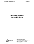
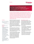
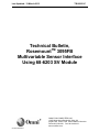
Last Updated: 12-March-2012 TB-980501C Technical Bulletin, TM Rosemount 3095FB Multivariable Sensor Interface Using 68-6203 SV Module OMNI FLOW COMPUTERS, INC. 12620 West Airport Boulevard, Suite 100 Sugar Land, Texas 77478 United States of America Phone-281.240.6161 Fax: 281.240.6162 www.omniflow.com 52-0003-0002/Rev C Page 1 of 18 TB-980501C RosemountTM 3095FB Multivariable Sensor Interface Using 68-6203 SV Module NOTE: User Manual Reference - This Technical Bulletin complements the information contained in the User Manual, applicable to Firmware Revision 21.74+/25.74+ and 23/74, +/27.74. Table of Contents Scope ............................................................................................................................................4 Abstract .........................................................................................................................................4 Important OMNI Flow Computer Compatibility Issues When Using SV Combo Modules.............4 Serial Communication Module Compatibility.............................................................................4 Other Known System Incompatibilities......................................................................................4 Equipment Ordering Limitations ................................................................................................5 Connectivity Issues When Connecting to the 3095FB Multivariable Transmitters: Multi-drop versus Point-to-Point .....................................................................................................................5 Advantages of Multi-drop Configurations ..................................................................................5 Disadvantages of Multi-drop Configurations .............................................................................5 Jumper Settings for the OMNI SV Combo Module........................................................................6 Setting the Address of the SV Combo Module..........................................................................6 Setting the Termination Jumpers for the Each of the SV RS-485 Ports....................................6 Initial Setup of the Rosemount™ 3095FB Multi Variable Transmitter ...........................................8 Connecting the 3095FB to the OMNI Flow Computer...................................................................9 3095FB Transmitter RS-485 Connections ................................................................................9 3095FB Transmitter Power Connections and Requirements ..................................................10 Isolation and Transient Protection Issues ...............................................................................10 Wiring Considerations When Replacing a Multi-dropped 3095FB Transmitter .......................10 Configuring the OMNI Flow Computer to use the 3095FB Multi Variable Transmitter................11 Configuring the Meter Run I/O ................................................................................................11 Selecting the Device Type ...................................................................................................11 Selecting the SV Combo Module Port..................................................................................11 Select Modbus Address for 3095FB ....................................................................................11 What I/O Points are Used and Why .....................................................................................11 Bi-directional Flow and 3095FB Transmitters ......................................................................12 Referencing 3095FB Variables Elsewhere in the Configuration ..........................................12 DP, Pressure and Temperature Setup Entries Needed ..........................................................12 Data Transferred between the 3095FB Transmitter and the OMNI Flow Computer ...................13 Polling Intervals for Process Variables and Critical Alarms.....................................................13 Critical 3095FB Alarms Monitored By the Flow Computer ......................................................13 Synchronizing the 3095FB and the Flow Computer Configurations............................................14 Viewing the 3095FB Data at the Flow Computer Front Panel.....................................................15 Installing, Replacing and Calibrating 3095FB Transmitters ........................................................16 Wiring Issues...........................................................................................................................16 Using the OMNI Flow Computer to Set the Modbus Address of the 3095FB .........................16 Using a Laptop PC to Trim the 3095FB Calibration ................................................................17 52-0003-0002/Rev C Page 2 of 18 TB-980501C RosemountTM 3095FB Multivariable Sensor Interface Using 68-6203 SV Module Figures Figure 1. OMNI Model 68-6203 Multivariable Interface Module - SV Combo Module .................6 Figure 2. Multi-drop Configuration with Flow Computer Terminated............................................6 Figure 3. Multi-drop Configuration with Flow Computer Non-terminated .....................................7 Figure 4. Unacceptable Configuration - Five Termination Points.................................................7 Figure 5. Point-to-Point Wiring Configuration...............................................................................7 Figure 6. RosemountTM 3095FB Multivariable Setup Switches and Jumpers ..............................8 Figure 7. RosemountTM 3095FB Multivariable Wiring Terminals................................................9 Figure 8. Labels for Rosemount 3095 RS-485 Serial Port are Eeversed. Label A is B (negative signal) and Label B is A (positive signal).....................................................................................10 52-0003-0002/Rev C Page 3 of 18 TB-980501C RosemountTM 3095FB Multivariable Sensor Interface Using 68-6203 SV Module Scope Firmware Revisions 21.74+/25.74+ and 23.74+/27.74+ of OMNI 6000/OMNI 3000 Flow Computers are affected by the issues contained in this Technical Bulletin. This Bulletin applies to Orifice/Differential Pressure Liquid Flow Metering Systems and to Orifice Gas Flow Metering Systems. Abstract The Rosemount 3095FB Multivariable sensor assembly is used to measure differential pressure (DP), static pressure (SP) and line temperature (T). Application of the 3095FB is limited to flow computer revisions 21, 23, 25 and 27 which work with differential head devices such as orifice meters, nozzles and venturi meters. Because the flow computer is limited to a maximum of four (4) meter runs it is also limited to a maximum of four (4) 3095FB multivariable transmitters. Data is accessed from the 3095FB transmitter via a 2 wire RS-485 data link at 9600 baud using Modbus protocol. Technically, it would have been possible to use one of the flow computer’s standard serial ports to communicate with the 3095FB but this would have caused several issues: Reduced the number of serial ports available for use with SCADA, PLCs and OMNICOM etc. Extra 'A’ type combo modules would have to be purchased simply to provide analog outputs in a minimum system requiring just the multivariables. OMNI chose to design a special ‘SV’ combo module which includes two (2), 2-wire RS-485 ports and six (6), 4-20 mA analog outputs. With this module it becomes possible to provide a powerful OMNI 6000/3000 system with the following specs: Four meter runs with Differential Pressure, Static Pressure and Temperature inputs Four communication ports for SCADA, PLC, Printer, OMNICOM etc Twelve Digital I/O for logic control Six digital to analog outputs This SV module is capable of connecting to one to four 3095FBs in various multi-drop configurations. A second SV combo module can be utilized in applications where point to point operation of more than two (2) multivariable transmitters is desirable. Important OMNI Flow Computer Compatibility Issues When Using SV Combo Modules The ‘SV’ combo modules are effectively serial I/O modules which have been specially designed to communicate with various multivariable transmitters. Changes have been made to the IRQ priorities to accommodate these ‘SV’ combo modules. These IRQ changes also involve the ‘Serial I/O Combo Modules’ that are used to connect to printers, OMNICOM, PLCs and SCADA devices. Serial Communication Module Compatibility ‘SV’ combo modules cannot be installed in flow computer systems containing RS-232-C Serial I/O Combo modules model type 68-6005. The IRQ settings on the 68-6005 serial combo module are not jumper selectable and are incompatible with the 'SV’ combo modules. The flow computer will not be able to initialize or boot up if this module is installed (this will be evident by a blank LCD screen which flashes its backlighting on and off every 1.5 seconds). The more recent 68-6205 serial module which is both RS-232-C and RS-485 compatible, has jumper selectable IRQ settings, these must be installed in the ‘IRQ 3’ position when an ‘SV’ combo module is present (TB-980503 for more details). Other Known System Incompatibilities At the time this bulletin was prepared, it was not possible to install both an ‘SV’ combo module and an ‘HV’ (Honeywell multivariable) combo module in the same unit. 52-0003-0002/Rev C Page 4 of 18 TB-980501C RosemountTM 3095FB Multivariable Sensor Interface Using 68-6203 SV Module Equipment Ordering Limitations Because of the compatibility issues raised in the previous paragraphs, it is not possible for the customer to retrofit existing flow computer installations with ‘SV’ combo modules. Any system which requires ‘SV’ combo modules, must be purchased new from OMNI, or the system must be returned to OMNI to be modified. Contact Sales at [email protected] for upgrade details and pricing. Connectivity Issues When Connecting to the 3095FB Multivariable Transmitters: Multi-drop versus Point-to-Point The 3095 FB multivariable transmitter is a four (4) wire device, two (2) power wires and two (2) wires for the RS-485 serial communication link. It can be connected in a ‘point-to-point’ or ‘multi-drop’ wiring configuration. Advantages of Multi-drop Configurations The advantages of multi-drop configurations are: Less wire may be needed to connect devices under certain conditions. This may or may not be the case depending upon equipment placement. One (1) OMNI SV Combo module can handle up to four (4) 3095 FB multivariable transmitters. An OMNI 3000 can be used in place of an OMNI 6000 and handle four (4) meter runs. Disadvantages of Multi-drop Configurations Disadvantages of multi-drop configurations are: Multiple Modbus IDs required. Each multi-dropped transmitter must have a unique Modbus ID which matches the Modbus ID selected within the flow computer for that meter run multivariable. Possibility of errors when replacing multivariable transmitters. Because of the multiple Modbus addresses it is not possible to simply take a transmitter off the shelf and install it in a multi-drop configuration. This is because transmitters come from Rosemount with the Modbus address defaulted to ‘1’ and there may already be a transmitter in the loop using that address. Adding a second transmitter with the same address as an existing transmitter would effectively cause a loss of signal on both transmitters (existing and new). Depending upon where the transmitter is in the wiring, ‘termination’ jumpers may or may not be required on the replacement transmitter. Transmitter interaction is possible. While not likely, a hardware failure in one transmitter could compromise the integrity of the shared RS-485 link causing a loss of flow signals for all meter runs. Calibrating a transmitter via a laptop computer requires the wiring to be disturbed. Care must be taken not to disconnect other transmitters in the same multi-drop loo. RS-485 termination requirements are more complex. RS-485 transmission wires must have only one beginning and one end (they cannot be used in a ‘star’ configuration). Both ends of the wire must be terminated, meaning only two (2) devices in the loop need terminating. In a point-to-point configuration, this simply means both the flow computer and transmitter are terminated. In a multidrop configuration, the user must ensure that only the end devices have the termination jumpers in. This means that some transmitters may have the terminating jumpers in while others may have them out. Remember that the OMNI may or may not be at the end of the wire so it may or may not be one of the terminated devices. Process variable update time may exceed the flow computers 500 msec cycle time. Critical measurement or control systems require that the process variables be input to the flow computer as fast as possible for best performance. 52-0003-0002/Rev C Page 5 of 18 RosemountTM 3095FB Multivariable Sensor Interface Using 68-6203 SV Module TB-980501C Jumper Settings for the OMNI SV Combo Module The Multi Variable ‘SV’ Combo module contains several sets of jumpers which must be installed correctly (Figure 1). Port 1 (3) Tx/RT S Le ds Recv Led Grn SV RS-48 5 Termination J umpers Both Jm pe rs I n = Port Term in ated Both Jm pe rs Ou t = Port N on-Term in ated A lwa ys RTS SV Address Jumper Jm p In = 1s t SV Co mb o Jm p Out = 2 nd SV Com bo A lways IRQ 2 2 P ort 2 (4) T x/R TS L eds Re d R ecv L ed Grn RTS T E R M GND T E R M RTS GND T E R M T E R M SV P ort 1 ( 3 ) SV Port 2 ( 4 ) Po rt Num bers in ( ) are f or 2 BRD S EL 4 IRQ nd SV M odu le Figure 1. OMNI Model 68-6203 Multivariable Interface Module - SV Combo Module Setting the Address of the SV Combo Module The flow computer can accept up to two (2) ‘SV’ Combo modules, each with a unique address determined by the ‘BRD SEL’ jumper shown in Figure 1. With this jumper fitted the flow computer will report that a ‘SV1’ module is installed and SV ports 1 and 2 will be available. Without this jumper in the ‘BRD SEL’ position the flow computer will report that a ‘SV2’ module is installed and SV ports 3 and 4 will be available. Note that a system can have a ‘SV2’ module without a ‘SV1’ being installed, in this case only SV ports 3 and 4 would be available. Setting the Termination Jumpers for the Each of the SV RS-485 Ports Multivariable RS-485 communication circuits must have two (2) ends only, a ‘star’ configuration with more than two (2) ends or a ‘loop’ configuration with no ends is not allowed. The devices at both ends of the circuit must be jumpered to provide termination. 3095 FB MV ID #1 Omni Flow Computer 3095 FB MV ID #2 3095 FB MV ID #3 This Device Must Be Terminated 3095 FB MV ID #4 This Device Must Be Terminated Figure 2. Multi-drop Configuration with Flow Computer Terminated Both jumpers marked ‘TERM’ must be installed to terminate a flow computer ‘SV’ port (Figure 1). Termination settings for the 3095FB are shown later in this Technical Bulletin. 52-0003-0002/Rev C Page 6 of 18 RosemountTM 3095FB Multivariable Sensor Interface Using 68-6203 SV Module TB-980501C This Device Must Be Terminated 3095 FB MV ID #1 3095 FB MV ID #4 Omni Flow Computer 3095 FB MV ID #2 This Device Must Be Terminated 3095 FB MV ID #3 Figure 3. Multi-drop Configuration with Flow Computer Non-terminated 3095 FB MV ID #1 3095 FB MV ID #2 3095 FB MV ID #3 3095 FB MV ID #4 Omni Flow Computer Star Configuration Not Allowed! Figure 4. Unacceptable Configuration - Five Termination Points All 4 MV Ports of Flow Computer Must Be Terminated 3095 FB MV ID #1 3095 FB MV ID #1 3095 FB MV ID #1 3095 FB MV ID #1 Omni Flow Computer Using Independent MV Ports Modbus IDs of 3095FBs Can Be The Same In This Point to Point Configuration All Four 3095FB Transmitters Must Be Terminated Figure 5. Point-to-Point Wiring Configuration In the point-to-point configuration each 3095FB transmitter is connected to an independent ‘SV’ port of the flow computer. Because each ‘SV’ port is now connected to only one (1) 3095FB, each 3095FB can now use the default Modbus address ‘1’, greatly simplifying transmitter replacement issues discussed in this Technical Bulletin. 52-0003-0002/Rev C Page 7 of 18 RosemountTM 3095FB Multivariable Sensor Interface Using 68-6203 SV Module TB-980501C Initial Setup of the Rosemount™ 3095FB Multi Variable Transmitter The 3095FB module has two (2) sets of DIP switches and a jumper set which must be setup according to the wiring configuration used to connect to the OMNI Flow Computer. PULL DOWN (B) PULL UP (A) AC TERMINATION All ON = Terminated All OFF = Un-Terminated o o o SECURITY o o OFF ON o o o o o Security OFF to allow configuration ON 1 2 3 S1 S2 ON 1 2 All ON For 9600 Baud Figure 6. Rosemount TM 3095FB Multivariable Setup Switches and Jumpers Place the security jumper in the ‘OFF’ position, this allows the OMNI Flow Computer to write to the 3095FB registers ensuring that the internal configuration matches the flow computer. Both baud rate switches S1 and S2 must be set to 9600; i.e., in the ‘ON’ position. The termination switches should be all ‘ON’ or all ‘OFF’ depending upon whether device termination is required. 52-0003-0002/Rev C Page 8 of 18 RosemountTM 3095FB Multivariable Sensor Interface Using 68-6203 SV Module TB-980501C Connecting the 3095FB to the OMNI Flow Computer Table 1. Back Panel Termination Assignments – SV Combo Module TERMINAL SIGNAL DESCRIPTION 1 Port # (3) RS 485 B wire 2 Port #1(3) RS 485 A wire 3 Port #2(4) RS 485 B wire 4 Port #2 (4) RS 485 A wire 5 Signal Return for 4-20mA Outputs 6 Signal Return for 4-20ma Outputs 7 4-20ma Analog Output # 5 8 4-20mA Analog Output # 6 9 4-20mA Analog Output # 3 10 4-20mA Analog Output # 4 11 4-20mA Analog Output # 1 12 4-20mA Analog Output # 2 A RS-485 B + PWR Figure 7. RosemountTM 3095FB Multivariable Wiring Terminals 3095FB Transmitter RS-485 Connections Two (2) terminals are provided marked A and B, these are connected to the A and B terminals of other multi-dropped 3095FBs and to the OMNI SV Combo module terminals. These connections should be made using twisted pair unshielded wire with a minimum gauge dependent upon the distance to be run. Use 22 AWG minimum, 18 AWG maximum for runs less than 1000 ft. Use 20 AWG minimum, 18 AWG maximum for runs of 1000 to 4000 ft. Shielded twisted pair cable can be used but may have an attenuating effect due to a higher capacitance per foot thereby limiting the maximum wire run length to less than 4000 ft. 52-0003-0002/Rev C Page 9 of 18 RosemountTM 3095FB Multivariable Sensor Interface Using 68-6203 SV Module TB-980501C 3095FB Transmitter Power Connections and Requirements Terminals marked ‘+’ and ‘-‘ are provided to connect the 3095FB to a 7.5 VDC. to 24 VDC. power supply. This power supply must be able to provide 10 mA per installed 3095FB plus an additional 100 mA which is required when any 3095FB in the system is transmitting data to the flow computer. Ripple on this power supply must be less than 2%. Wiring gauge should be selected as per the previous paragraph and can be unshielded un-twisted pair, but for best performance should be shielded and twisted. 4000 Ft. Maximum OMNI FLOW COMPUTER SV PORT #1 SV PORT #2 SV PORT #3 SV PORT #4 B Termination ON No Stubs over 6 FT RS485 BUS A B A B A B A 7.5 VDC to 24 VDC Power Supply 150 mA Minimum A RS485 B A RS485 B A RS485 B + PWR - + PWR - + PWR - Termination OFF Termination OFF Termination ON + - Figure 8. Rosemount 3095 RS-485 Serial Ports in a Multidrop System. If there are communications problems swap wires A and B on one end and try again. Isolation and Transient Protection Issues The design of the 3095FB transmitter does not provide any DC isolation between the power connections and the RS-485 connections. Applying voltages between the power wiring and RS-485 wiring greater than the allowable common mode voltage of a RS-485 driver circuit could damage the 3095FB. The OMNI Flow Computer SV port is optically isolated and can handle common mode voltages of +/- 250 VDC with respect to chassis ground. Inductive base transient protectors including the Rosemount Model 470 can adversely affect the output of the 3095FB. Do not use the Model 470 for transient protection with the 3095FB. If transient protection is desired, install the optional ‘Transient Protection Terminal Block’ described in Appendix B of the Rosemount 3095FB Manual (pub. 00809-0100-4738). Wiring Considerations When Replacing a Multi-dropped 3095FB Transmitter If downtime of other 3095FB transmitters in a multi-dropped system cannot be tolerated, make sure to provide a suitable and safe means of disconnecting power and signal from each individual 3095FB transmitter. NOTE: Because of the power requirements of the RS-485 the 3095FB cannot be made ‘intrinsically safe’. This means that proper safety procedures must be followed before any covers are removed from any devices or junction boxes located in hazardous areas. Refer to Rosemount 3095FB Manual (publication 00809-0100-4738) for correct installation of the 3095FB transmitter. 52-0003-0002/Rev C Page 10 of 18 RosemountTM 3095FB Multivariable Sensor Interface Using 68-6203 SV Module TB-980501C Configuring the OMNI Flow Computer to use the 3095FB Multi Variable Transmitter Configuring the Meter Run I/O Selecting the Device Type The existing ‘Select Turbine Y/N’ entry in the ‘Config Meter Run’ menu has been changed to ‘Select Device Type’. Valid selections at this point are: 0 = DP Sensor 1 = Turbine Meter 2 = 3095FB Multivariable 3 = SMV 3000 Multivariable When ‘2’ is selected the following entries appear: Selecting the SV Combo Module Port The number of ports available depends upon what SV Combo Modules are fitted in the flow computer. Ports 1 and 2 are available when SV Combo Module #1 is fitted ports 3 and 4 when SV Combo Module #2 is present. It is possible to have SV ports 3 and 4 without SV ports 1 and 2 assuming SV Combo Module #2 is the only SV module fitted. Select Modbus Address for 3095FB In point-to-point mode (i.e., each SV port is connected to a single 3095FB) it is recommended that you select Modbus ID ‘1’ at this point. This is the default ID used by Rosemount when the 3095 is shipped. In multi-drop mode each 3095FB connected to a SV port must have its own address which can be between 1 and 247. What I/O Points are Used and Why Even though the multivariable data is obtained serially and not via analog input channels, the flow computer must have a storage structure in RAM to place the data. OMNI has chosen to treat the data as closely as possible to that obtained by conventional means and use the same physical I/O RAM structure as is used for analog inputs. The main difference being that with analog and pulse inputs you would manually assign the I/O points to be used for each input. When using the 3095FB multi variable, the flow computer automatically assigns three (3) I/O point assignments for the DP, temperature and pressure sensors within the 3095FB. The I/O point numbers are allocated in the order that the 3095FBs are configured using the device type three (3) entries (it has nothing to do with SV port or SV module numbers). The starting I/O point for the first 3095FB configured is the first point immediately after the last I/O point used by any other A, B, E/D, E or H combo modules in the system (Tables 2 and 3). Table 2. I/O Points Used by SV Combo Modules – Example 1 EXAMPLE 1 CONFIGURATION 6000 – 2A – 1B – 1SV A1 Combo Module I/O Points 1-4 A2 Combo Module I/O Points 5-8 B1 Combo Module I/O Points 9 - 12 st DP=13, T=14, P=15 nd DP=16, T=17, P=18 rd DP=19, T=20, P=21 th DP=22, T=23, P=24 1 3095FB Configured Uses 2 3095FB Configured Uses 3 3095FB Configured Uses 4 3095FB Configured Used 52-0003-0002/Rev C Page 11 of 18 RosemountTM 3095FB Multivariable Sensor Interface Using 68-6203 SV Module TB-980501C Table 3. I/O Points Used by SV Combo Modules – Example 2 EXAMPLE 2 CONFIGURATION 6000 – 1A – 1E/D – 1SV A1 Combo Module I/O Points 1-4 A2 Combo Module I/O Points 5-8 B1 Combo Module I/O Points 9 - 12 st DP=13, T=14, P=15 nd DP=16, T=17, P=18 rd DP=19, T=20, P=21 th DP=22, T=23, P=24 1 3095FB Configured Uses 2 3095FB Configured Uses 3 3095FB Configured Uses 4 3095FB Configured Used Bi-directional Flow and 3095FB Transmitters Sometimes it is necessary to use a process variable obtained from a 3095FB in more than one meter run. For example, when measuring bi-directional flow it is customary to configure one meter run within the OMNI Flow Computer as ‘forward’ flow and a second meter run as ‘reverse’ flow. To do this, simply configure both meter runs as ‘Device Type = 2 (3095FB Multi Variable)’, select the same SV port and Modbus ID, the OMNI Flow Computer will recognize that both meter runs are using the same 3095FB device and allocate only one set of I/O assignments. Referencing 3095FB Variables Elsewhere in the Configuration While the DP, temperature and pressure obtained from the 3095FB multi variable are used to calculate flow, it may also be necessary to use either the temperature and/or the pressure to correct a densitometer device mounted in close proximity. To do this simply note the I/O point numbers automatically assigned to the 3095FB when it was configured and reuse these point numbers as needed. DP, Pressure and Temperature Setup Entries Needed Once I/O points have been assigned to the 3095FB multi variable transmitter, by the flow computer the Differential Pressure, Temperature and Pressure setup menus become active. Data entries in these menus are: Low Alarm Setpoint High Alarm Setpoint Override Value Override Code 0 = Never Use Override Value 1 = Always Use Override Value 2 = Use Override on a 3095FB Communication Failure or Critical Error 3 = Use Last Hour’s Average on a 3095FB Communication Failure or Critical Error 4mA Value (read only) 20mA Value (read only) Damping Code 0 = 0.108 Seconds 1 = 0.216 Seconds 2 = 0.432 Seconds 3 = 0.864 Seconds (Default) 4 = 1.728 Seconds 5 = 3.456 Seconds 6 = 6.912 Seconds 7 = 13.824 Seconds 8 = 27.648 Seconds 52-0003-0002/Rev C Page 12 of 18 TB-980501C RosemountTM 3095FB Multivariable Sensor Interface Using 68-6203 SV Module All of the data entries are changeable when using analog transmitters but when using the 3095FB multi variable transmitter the 4mA and 20mA scaling values cannot be changed. The upper and lower range of the 3095FB sensors are fixed by design. The OMNI Flow Computer simply reads these values and displays them in the 4mA and 20mA fields for information only. While the 3095FB transmitter has internal alarm setpoints and alarm status points, OMNI has chosen to ignore the 3095FB integral alarming functions and use the existing flow computer alarm setpoints and alarm status points. The Low and High Alarm Setpoints of the flow computer therefore behave exactly as they would with an analog transmitter. The 3095FB Critical Alarm states are monitored continuously. Data Transferred between the 3095FB Transmitter and the OMNI Flow Computer In operation the OMNI Flow Computer automatically sets up the 3095FB transmitter to use the correct floating point format and units of measure needed to match the flow computer’s configuration. The OMNI continuously reads the following data: Process Variables DP, Pressure and Temperature Individual Transmitter Sensor Ranges Critical Transmitter Alarms (Sensor failures etc) Transmitter Information (Body and Fill material etc) Manufacturers Code Transmitter Tags Polling Intervals for Process Variables and Critical Alarms The message poll scheme comprises regular reads of the process variable values and critical alarms every 200msec per 3095FB connected to a flow computer SV port. This means that in a multi-drop system with four (4) transmitters the process variable update time will be 4 x 200msec or 800msec. Critical 3095FB Alarms Monitored By the Flow Computer Critical alarm points within the 3095FB are monitored and mapped into the OMNI Flow Computer Modbus database as shown in Table 4: 52-0003-0002/Rev C Page 13 of 18 RosemountTM 3095FB Multivariable Sensor Interface Using 68-6203 SV Module TB-980501C Table 4. Alarms Associated with the 3095FB Providing Data to Meter Run ‘n’ MODBUS ADDRESS ALARM POINT DESCRIPTION ACTION TAKEN IF ALARM IS ACTIVE (SEE ALSO ‘FAILURE CODE SETTING) 1n83 DP signal 10% above upper range limit DP transmitter failure flagged 1n84 DP signal 10% below lower range limit DP transmitter failure flagged 1n85 Pressure signal 10% above upper range limit Pressure transmitter failure flagged 1n86 Pressure signal 10% below lower range limit Pressure transmitter failure flagged 1n87 Pressure sensor is shorted Pressure transmitter failure flagged 1n88 Pressure sensor bridge is open circuit Pressure transmitter failure flagged 1n89 Temperature signal 10% above upper range limit Temperature transmitter failure flagged 1n90 Temperature signal 10% below lower range limit Temperature transmitter failure flagged 1n91 Temperature RTD is disconnected Temperature transmitter failure flagged 1n92 Sensor internal temperature above upper range limit DP, P and T, transmitter failures flagged 1n93 Sensor internal temperature below upper range limit DP, P and T, transmitter failures flagged 1n94 Critical 3095FB sensor electronics failure DP, P and T, transmitter failures flagged 1n95 Security jumper of 3095FB is set to ‘Write Protect’ DP, P and T transmitter failures flagged if write to 3095FB is attempted and fails *1n96 No communications between the OMNI and 3095FB unit *1n96 is flow computer generated DP, P and T, transmitter failures flagged Synchronizing the 3095FB and the Flow Computer Configurations To ensure that the flow computer correctly interprets the 3095FB data, the flow computer continuously verifies that the configuration of the 3095FB transmitter matches that required by the flow computer. Additional message polls verifying this data are interleaved with the normal message polls used to retrieve the process variables and alarms. NOTE: Numbers in ( ) are Modbus addresses within the 3095Fb database ++ The flow computer will attempt to correct the database of the 3095FB transmitter if mismatches are detected for these variables. * The flow computer will adjust its database to agree with the 3095FB database if mismatches are detected for these variables. 52-0003-0002/Rev C Page 14 of 18 RosemountTM 3095FB Multivariable Sensor Interface Using 68-6203 SV Module TB-980501C Critical 3095FB configuration data which is checked every 10 seconds is: Floating Point Number Format Measurement Engineering Units of Measure Minimum and Maximum Ranges of each Signal Transmitter Identification (Information Only) Damping Factors **(0132) **(0060 - 0062) *(7407 - 7416) (0001 - 0011) **(7421, 7424, 7427) Transmitter ASCII Tags (3x8 characters) Transmitter Information (Materials of Construction) **(0032 - 0047) (0017 - 0029) Viewing the 3095FB Data at the Flow Computer Front Panel Differential Pressure, Temperature and Pressure variables and averages are viewed using the normal key press combinations as described in the OMNI Flow Computer User Manual. A display list of 3095FB transmitter information can be displayed by pressing ‘Setup’ ‘n’ ‘Enter’. Data is organized by SV port number ‘n’ and in the order that the transmitters were configured. The information and diagnostic data is displayed (example shows first transmitter on the #1 SV port as an example): NOTE: 1st digit is the SV port number, 2nd digit is the Modbus Address of the 3095FB SV Port 1 ‐ 1 Manufactur Rosemount Model 3095/Modbus Out Board Rev 108.0 If you continue to scroll down, the following data will be displayed: Sensor Mod Rev 142 Sensor Serial 839193 Xmtr Ser 19644 H/W Rev 3 Modbus Rev 5 Sensor Type GP DP Range ‐250 to 250 SP Range 0‐800 psi PT Range‐40 to 1200F Isolator Mat’l 316SS Fill Fluid Silicone Flange Mtr’l 316SS Flange Type Coplaner Drain/Vent 316SS O‐Ring PTFE (Teflon) Seal type None Seal Fill None Seal Isolator None Number of Seals None 52-0003-0002/Rev C Page 15 of 18 RosemountTM 3095FB Multivariable Sensor Interface Using 68-6203 SV Module TB-980501C Installing, Replacing and Calibrating 3095FB Transmitters Wiring Issues If downtime of other 3095FB transmitters in a multi-dropped system cannot be tolerated, make sure to provide a suitable and safe means of disconnecting power and signal from each individual 3095FB transmitter. NOTE: Because of the power requirements of the RS-485 the 3095FB cannot be made ‘intrinsically safe’. This means that proper safety procedures must be followed before any covers are removed from any devices or junction boxes located in hazardous areas. Refer to Rosemount 3095FB Manual (publication 00809-0100-4738) for correct installation of the 3095FB transmitter. Using the OMNI Flow Computer to Set the Modbus Address of the 3095FB The 3095FB transmitter will normally be shipped with a default Modbus address of ‘1’. While this is fine for a point to point installation, it will cause a problem if two (2) or more devices have the same Modbus ID in a multi-drop scheme. The Modbus ID of a transmitter can be set using the ‘Configurator User Interface PC Software’ available from Rosemount. It is anticipated though that some situations may arise where a 3095FB transmitter must be installed or replaced without this software being available. In this case the OMNI Flow Computer can be connected to a 3095FB in the point to point mode using any available SV port and the Modbus ID changed to what is required in the flow computer configuration. CAUTION: This procedure involves ‘broadcast’ transmitting a Modbus address out of a SV port. All devices connected to this SV port will have their Modbus address set to the ID broadcast. This would cause data collisions and a complete loss of communication when more than one 3095FB transmitter is connected. Be sure to temporarily disconnect any 3095FB transmitters which addresses you do not want to change. Proceed as follows: 1. Setup the 3095FB as described previously in the section titled ‘Initial Setup of the Rosemount 3095FB Multi Variable Transmitter’. 2. Setup the 3095FB to be RS-485 terminated. 3. Connect the transmitter to any open SV port (terminal A to A, B to B). The SV port should be jumpered for RS-485 termination. If this SV channel is not an open channel, all 3095FB transmitters except the one needing the address change must be disconnected. 4. Apply power to the 3095FB transmitter. 5. At the flow computer front panel press the following keys: [Alpha Shift] [Diag] The computer will enter the Diagnostic mode. [Setup] [n] [Enter] Where ‘n’ is the SV port number that the 3095FB is connected to. 6. The following warning screen may display (SV port 1 is used as an example) or the screen in (7) will display. SV Port 1 # 1 This Port Currently Configured For Use! Continue (Y/N)? This means that the flow computer has detected that this SV port is currently configured to communicate with one (1) or more transmitters. You may or may not have selected the wrong SV port (refer to CAUTION). 52-0003-0002/Rev C Page 16 of 18 RosemountTM 3095FB Multivariable Sensor Interface Using 68-6203 SV Module TB-980501C 7. If you wish to continue with the address broadcast operation enter ‘Y’ and the following screen will display. SV Port 1 # 1 Change Xmtr Address New Address _ Idle 8. Scroll down to ‘New Address’ and enter the address required. Press ‘Enter’ and the following message will display. Sending New Address 9. The flow computer will wait a short time and then attempt to communicate with the 3095FB using the new address. If communications are established the following message will be displayed for a few seconds. Address Changed The following message will display for a second or two (2) should the transmission fail. Failed Change Should this message appear check your wiring, switch and jumper settings and repeat the procedure. 10. Disconnect and reinstall 3095FB to the appropriate SV port for normal operation making sure to observe the termination requirements of only two (2) devices at the end of a loop being terminated. Using a Laptop PC to Trim the 3095FB Calibration The flow computer provides no way of calibrating or trimming the output of the 3095FB multi variable transmitter. To calibrate the transmitter use the ‘Configurator User Interface PC Software’ available from Rosemount. The user must disconnect the 3095FB needing calibrating and connect it in point to point mode with the Laptop or PC running the Rosemount Interface Software. Remember to follow all correct safety procedures when removing transmitter covers or junction boxes. Read the manufacture’s warnings and recommendations as printed in the 3095FB manual. Be aware that when removing a transmitter from a multi-drop installation, wiring may be disturbed and disruption of the circuit may cause a loss of all measurement signals due to loss of power, signal or RS-485 termination. 52-0003-0002/Rev C Page 17 of 18 RosemountTM 3095FB Multivariable Sensor Interface Using 68-6203 SV Module TB-980501C DOCUMENT REVISION HISTORY DOCUMENT INITIAL RELEASE DATE .................................................................. 22-May-2003 REVISION A B C DATE 22-May-2003 13-April-2009 12-March-2012 PURPOSE / CHANGE REQUEST Maintained on the Web - Initial release DCR 090101 DCR 120031 52-0003-0002/Rev C Page 18 of 18