1
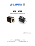
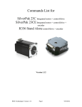
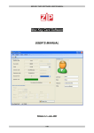
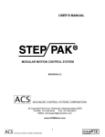
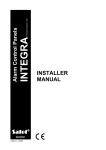
Simple Step
INTEGRATED STEP MOTOR,
DRIVER, AND CONTROLLER
USER MANUAL
Lin Engineering
Page 1
5/15/2003
TABLE OF CONTENTS
SECTION 1: INTRODUCTION TO SIMPLE STEP...............................................3
PLEASE READ BEFORE USING SIMPLE STEP ................................................................. 4
DISCLAIMER..................................................................................................................... 4
ELECTRICAL SPECIFICATIONS......................................................................................... 5
COMMUNICATIONS SPECIFICATIONS............................................................................... 5
DIMENSIONS .................................................................................................................... 6
OPERATING SPECIFICATIONS ......................................................................................... 6
FEATURES ....................................................................................................................... 7
DEVELOPER’S KIT LIST ................................................................................................... 7
SECTION 2: CONNECTORS ...............................................................................8
SECTION 3: GETTING STARTED .......................................................................9
SETUP FOR HYPERTERMINAL ....................................................................................... 10
SETUP FOR WINDOWS APPLICATION ............................................................................ 10
SECTION 4: USING THE DIGITAL I/O ..............................................................11
INPUT CONNECTIONS .................................................................................................... 11
OUTPUT CONNECTIONS ................................................................................................ 13
CONNECTING AN LED TO AN I/O.................................................................................... 14
CONNECTING MULTIPLE DRIVERS ................................................................................. 15
CHANGING ADDRESSES ................................................................................................ 15
SECTION 5: SOLDERING ACCESSORY PIECES............................................16
PUSH BUTTON ............................................................................................................... 16
OPTO SENSOR .............................................................................................................. 17
SECTION 6: SIMPLE STEP COMMANDS SET (HIGHLIGHTS) .......................18
PROGRAMMING SYNTAX ............................................................................................... 18
ROTATE MOTOR IN THE POSITIVE AND NEGATIVE DIRECTION ....................................... 19
CHANGING THE VELOCITY............................................................................................. 20
CHANGING THE ACCELERATION FACTOR ..................................................................... 20
LOOPS .......................................................................................................................... 20
SETTING THE CURRENT ................................................................................................ 21
THE SKIP COMMAND ..................................................................................................... 21
STORING PROGRAMS .................................................................................................... 21
ADJUSTING THE STEP RESOLUTION .............................................................................. 21
THE HALT COMMAND .................................................................................................... 22
RUNNING MULTIPLE MOTORS ........................................................................................ 22
EXAMPLES ..................................................................................................................... 23
SECTION 7: SOFTWARE DOWNLOADS .........................................................24
Lin Engineering
Page 2
5/15/2003
1. Introduction To Simple Step
The Simple Step is designed to allow for rapid implementation of stepper motors
in products requiring automation.
With a fully intelligent controller attached to the back, the Simple Step accepts
high level commands from an RS232/RS485 link. The controller only adds 0.5”
to the length of the motor which otherwise is a standard Lin Engineering Size 17
High Torque Step Motor.
The Simple Step unit is supplied
with a developer’s kit, enabling users
to easily implement their own
programs.
An RS485 to RS232
converter card is also given, along
with a DB-9 connector cable and
accessory pieces. The converter
card
provides
the
connection
between your Simple Step Unit and
your PC. Commands can be issued
from any serial terminal program
(such as HyperTerminal) or from the
Simple Step Windows Application,
which can be downloaded from Lin
Engineering’s website. Accessory
pieces such as a red push button
switch, an Opto Sensor, and a 4-pin
connector for the converter card, are
included. Also, additional wiring for
I/O’s are provided. The commands
to the Simple Step are intuitive and
simple. For example the command
A10000 will move the
stepper motor to Absolute Position 10000 (steps). (This communications
protocol is compatible with devices that use the Cavro DT or OEM protocol).
The Simple Step is also capable of stand alone operation with no connection to a
PC. It can be set to execute a preset string of commands upon power up.
Commands include nested loops, execution halt pending a switch closure, and
much more. It is also possible to daisy chain up to 16 different Simple Step units.
This user manual is a complete guide to setting up the Simple Step unit. It also
contains information on various types of inputs and outputs your Simple Step unit
can be used with. In addition, a highlighted list of commands for programming
the Simple Step has been provided.
Lin Engineering
Page 3
5/15/2003
SIMPLE STEP INSTALLATION NOTES
Thank you for purchasing the Simple Step Integrated Motor & Controller. The
Simple Step is warranted to be free of manufacturing defects for 1 year from the
date of purchase.
PLEASE READ FIRST BEFORE USING SIMPLE STEP
Before you start, ensure that there is a suitable DC power supply. A current
limited lab supply is recommended for first time users to guard against the
possibility of miswire. In addition, in order to prevent any harm to the controller
board, do not disconnect the unit while power is still being supplied. Do not
exceed 40VDC under any circumstances.
DISCLAIMER
Lin Engineering reserves the right to make changes without further notice to this
product to improve reliability, function, or design. Lin Engineering does not
assume any liability arising out of the application or use of any product or circuit
described herein; neither does it convey any license under its patent rights of
others.
The Simple Step Integrated Motor & Controller and Lin Engineering logo are trademarks of Lin
Engineering.
Lin Engineering
Page 4
5/15/2003
ELECTRICAL SPECIFICATIONS
Power Supply Requirements
Voltage
+12 VDC to +40 VDC
Motor Specifications
NEMA Size 17
Motor Rated Current
4118S
4118M
4118L
0.9 Amps RMS
1.4 Amps RMS
1.1 Amps RMS
Holding Torque 4118S
4118M
4118L
38.4 oz-in
72.0 oz-in
84.8 oz-in
Steps per Revolution (1.8° Motor)
400, 800, 1600, 3200, 6400, 12800
Digital I/O Specifications
Number of I/O
Number of Inputs
Input Voltage
Input Current
Pull-up Resistors
Protection
2
2
+0 VDC to +24 VDC
700 mA
10k Ω
Static Protection to the microprocessor
COMMUNICATION SPECIFICATIONS
Interface Type
Baud Rate
# Bits per character
Parity
Stop Bit
Flow Control
Lin Engineering
RS485 to RS232 converter card
9600 bps
8 Data
None
1
None
Page 5
5/15/2003
DIMENSIONS
A. Motor Front Shaft Extension Length
Standard length is 0.94”. Customized length is available.
B. Motor Shaft Diameter
Standard shaft diameter is 0.1968”. Customized diameter length is also
available.
C. Overall Body Length
Motor body length is available in various lengths
Model 4118S (2.69”)
Model 4118M (2.92”)
Model 4118L (3.24”)
OPERATING SPECIFICATIONS
Maximum Step Frequency
Operating Temperature Range
Storage Temperature Range
Lin Engineering
10k pps
0 to 50 °C
-20 to 70 °C
Page 6
5/15/2003
FEATURES
•
•
•
•
•
•
•
•
•
•
•
•
•
•
Single 4 wire bus linking up to 16 stepper motors
1.50 Amp Chopper (PWM) Driver
Operates from 12V to 40V
Stand alone operation with no connection to a PC
Execution Halt pending switch push button
Pre-wired for Opto Switch inputs
1/2, 1/4, 1/8, 1/32, 1/64 step resolution
Homes to an Opto or Switch closure with a single command
Fully programmable ramps and speeds
Two digital I/O and two fixed input channels
Switch selectable address
Software selectable "Move" and "Hold" currents
Hold Current automatically selected upon move completion
Simple DB9 connection
DEVELOPER’S KIT LIST
•
•
•
•
Simple Step Integrated Motor and Controller
RS485 to RS232 converter card
A DB-9 female connector cable, a switch push button, Opto Sensor, a 4
Pin connector for the converter card, and extra wiring for I/O
User Manual
Lin Engineering
Page 7
5/15/2003
2. Connectors
A DB-9 female connector cable receives power and provides the control
connections for the Simple Step module. On the opposite end of the DB-9
female connector cable, there is a 4 pin connector provided for the converter
card in order for the driver to communicate with the PC. This allows the user to
solder and program the switch push button and the Opto Sensor, enabling
several options. The two I/O wires are colored blue and black. This will allow for
options such as solenoids, relays, opto isolators, LED’s and many other input
and output connections. See Figure 2.1 for details.
Pin #
1
2
3
4
5
6
7
8
9
Color
Red
Black
Brown
Black/White
Orange
Green
White
Blue
Yellow
Function
+V (Main power In)
I/O
RS485B
RS485A
Switch Closure to GND (IN)
GND (-V of main pwr in)
Opto Sensor Phototransistor (IN)
I/O
Opto Sensor LED (Power Out)
Input*
1
4
3
2
Table 2.1
Figure 2.1: DB-9 Female Cable Connector (Rear View)
*Inputs are labeled 1, 2, 3 and 4 for programming the ‘Halt’ and ‘Skip’
Commands. See page 21 and 22 for more information.
Lin Engineering
Page 8
5/15/2003
3. Getting Started
1. Connect the DB-9 Female Cable to the back of the Simple Step unit.
2. On the opposite end of the DB-9 cable, there is a 4 pin female connector.
Connect this female mating connector to the header of the converter card
(RS485 to RS232 converter card).
3. Then connect two wires from the converter card to a power supply. Plus
and minus signs should already be allocated on the converter card.
4. Connect one end of a serial cable to the converter card, and the other end
to a serial port on a PC (This cable is not provided in the kit.)
5. Turn on your Power Supply (See Figure 3.1 below).
WARNING: DO NOT DISCONNECT THE UNIT WHILE POWER IS STILL
BEING SUPPLIED.
Figure 3.1
Lin Engineering
Page 9
5/15/2003
SETUP FOR HYPERTERMINAL
Please follow these steps in order to properly set up hyperterminal:
1. Open a terminal from your PC by following these steps:
Start Menu Æ Programs Æ Accessories Æ
Communications Æ HyperTerminal
2. Assign a name for your terminal
3. Make sure your COMM connection corresponds to the same COMM
connection as your PC serial port (i.e. COMM 1, COMM 2, etc.)
4. Set your Port Settings to default (i.e. 9600 baud, 8 data, no parity, 1 stop
bit, no flow control) To get to your Port Settings, perform the following
steps:
File Æ Properties Æ Settings
5. Turn on local echo by going to:
FileÆ Properties ÆSettings Æ ASCII Setup:
Click on the box for “Echo Typed Characters Locally” and click on the box
for “Send Line ends with line feeds”. These options will be useful when
typing commands in HyperTerminal.
6. Click OK
7. Now you can type your commands
8. Example: /1A10000R
o This will run driver 1 to the Absolute position 10000
o Visit www.linengineering.com for a full list of commands
SETUP FOR WINDOWS APPLICATION
1. Go to www.linengineering.com Æ Click on the Integrated Motors Icon Æ
Windows Application
2. Install Simple Step onto your PC
3. Open the application
4. Click on Settings, on the bottom right corner and type the correct COM
port. Be sure this corresponds with the correct serial port on your PC
5. Begin writing your commands (see the Quick Reference Guide for the
Windows Application at www.linengienering.com)
Lin Engineering
Page 10
5/15/2003
4. Using the Digital I/O
The Simple Step contains two fixed inputs and two digital bidirectional I/O’s. It is
possible to receive input from external devices such as sensors, switches, or
PLC outputs. Outputs such as relays, solenoids, LED’s and PLC inputs may be
controlled from the Simple Step Unit.
All Input and I/O lines feature internal 20k Ω pull-up resistors. The I/O lines in
addition feature a switch closure to ground, which can be used to drive loads
connected externally of up to 2.4 mA at 24V, or as low as 0.5 mA at 5V. The I/O
lines should not be actively driven high, because of the internal switch closure to
ground. (Use a pull-up resistor of 300 Ω or greater and an open collector style
pull-down on these particular lines).
INPUT CONNECTIONS
Connecting a Switch Push Button
A Red Capped Switch Push Button is provided in your kit. After
completing the ‘Getting Started’ section, you are now ready to program
an input. Please refer to the ‘Soldering Accessory Pieces’ on page 16
in order to use your switch push button. Figure 4.1 shows a circuit
schematic of how the switch push button is configured.
Figure 4.1
Using HyperTerminal, here is how to program your Simple Step Unit to
move 1000 steps in the positive direction each time you press the
button. Assuming the motor address is set to 1 (see the ‘Changing
Addresses’ section on page 15), type in the following code:
/1gH14P1000G0R
Lin Engineering
Page 11
5/15/2003
Connecting a TTL Interface
This enables the user to have one Simple Step unit’s output to be
another Simple Step unit’s input. Below, Figure 4.2 shows the input
driver on the left, and the output driver on the right.
Figure 4.2
Be aware of the possibility of a ground shift between the output driver
and the input driver. The wiring between the two drivers should be a
short 6 inch distance. If your wiring is too long, it is possible that the
ground voltage on the input side may be as high as 2 VDC, thus not
enabling this connection to work properly. To connect motors further
apart, use an opto isolator, as shown in the following section. It is also
recommended to connect multiple motors as shown on page 15.
Connecting an Opto Isolator
Connection of two motors is possible using an opto isolator. Be sure to
use a transistor opto that has a current, Ic > 1mA at IF = 20mA.
Figure 4.3
Lin Engineering
Page 12
5/15/2003
OUTPUT CONNECTIONS
Connecting an Opto Sensor
An Opto Sensor is provided in your developer’s kit. After completing
the ‘Getting Started’ Section, you can now program the Opto in
HyperTerminal. Please refer to page 17 for Soldering the Opto.
Figure 4.4
Here is how to program your Simple Step Unit to wait for a switch
closure on pin 2, home the stepper to the opto, move to position 1000,
then move to position 0:
/1H11ZA1000A0R
Driving a Relay
It is necessary to place a 1N4001 diode across the relay as shown in
order to protect against inductive spikes.
Figure 4.5
Example: To activate the relay, then wait for 500 milliseconds, and
then deactivate the relay, type in the following commands:
/1gJ3M500J0G5R
Lin Engineering
Page 13
5/15/2003
Driving a small DC Motor
A simple connection shown in Figure 4.6 will allow a 5V to 24V DC
motor to run with your Simple Step Unit.
Figure 4.6
Example: To turn on a driver, or an I/O pin, use the ‘J’ function, as shown
in the previous example. For ease of purpose, call J3 to turn on both
drivers, and use J0 to turn off both drivers.
/1J3M1000J0R
CONNECTING AN LED TO AN I/O
Since the Inputs and Outputs are tied down together to make a
bidirectional I/O line, there is about 0.002 Amps running through the line when it
should be off. When connecting an LED, there is a slight chance that the light
may appear dim when it is should appear to be completely off. If this happens,
an easy solution is to add a 20V Zener Diode between the LED and the circuit
board.
Figure 4.7
Lin Engineering
Page 14
5/15/2003
CONNECTING MULTIPLE DRIVERS
•
•
Ensure that each unit has its own unique address if you choose to have
different motions per unit. If you choose to run the same motion on
multiple units, then the same address for each unit may be used.
Figure 4.8 shows a basic schematic of the connections between two
motors and the converter card
Figure 4.8
CHANGING ADDRESSES
•
•
•
Locate the channel selector on the bottom of the Simple Step
Using a small flat screwdriver, turn dial to the desired channel
See Figure 4.9 below
Figure 4.9
Lin Engineering
Page 15
5/15/2003
5. Soldering Accessory Pieces
PUSH BUTTON
The push button needs to be soldered to wire 5 (Orange) and wire 6 (Green).
There is no difference in polarity for the push button, therefore, wire 5 and 6 can
be interchanged with the push button terminals.
Figure 5.1
Now you can program your switch push button. See ‘Examples’ in Section 6.
Note: When programming a specific input, note that:
Input 1 corresponds to Pin 2
Input 2 corresponds to Pin 8
Input 3 corresponds to Pin 7
Input 4 corresponds to Pin 5
See the commands list on how to program switches and halt statements.
Lin Engineering
Page 16
5/15/2003
OPTO SENOSR
The opto sensor uses wire 6 (Green), wire 7 (White), and wire 9 (Yellow). Four
wires are already connected to the opto sensor, colored Red, Black, White, and
Green. On the opto sensor, wires Green and Black are both Ground, which need
to be soldered together, then soldered to wire 6 (Green) on your DB-9 cable.
Then the red wire on the opto sensor needs to be soldered to wire 9 (Yellow) on
your DB-9 cable. And the white wire on the sensor needs to be soldered to wire
7 (White) on your DB-9 cable.
Opto Sensor
Green Æ
Black Æ
Red Æ
White Æ
Cable
Green
Green
Yellow
White
Table 5.1
Figure 5.2
Now you can program your Opto Sensor. See ‘Examples’ in Section 6.
Note: When programming a specific input, note that:
Input 1 corresponds to Pin 2
Input 2 corresponds to Pin 8
Input 3 corresponds to Pin 7
Input 4 corresponds to Pin 5
Lin Engineering
Page 17
5/15/2003
6. Simple Step Command Set
Commands to the Simple Step driver and controller are single alpha characters
normally followed by a numeric value. The alpha character represents “what to
do” and the numeric value represents “how much to do it”.
Values for desired velocities, accelerations, positions, stepping resolutions, and
currents can all be set. You can also query the program what position it is
currently at and what velocity it currently possesses. Creating loops within the
strings are easily possible, and storing these strings for later execution can also
be done. These strings are stored on the EEPROM, enabling the Simple Step to
power up into a mode of your choice, enabling the Unit to run as a stand alone
module.
For a complete list of commands, please visit www.linengineering.com and look
for Products Æ Integrated Motors Æ Simple Step.
PROGRAMMING SYNTAX
When typing in commands, always follow this format:
Start Character
/
Simple Step address
1-9*
Commands
Command string
End of string
<CR>
*Addresses for 10-16 use a different numbering system, described on page 22.
The forward slash tells the computer that you are going to give it a command.
The address number lets the computer know which Simple Step unit you want to
program. The command string is your actual command, described in detail in the
following sections. After typing in your command, you must type in the letter ‘R’,
which stands for ‘Run’. This will tell the computer to run the command. Lastly,
by pressing Enter, it tells the computer that you are finished with your string. In
the following descriptions and example, we will assume that the motor address
you wish to program will be motor address one.
Lin Engineering
Page 18
5/15/2003
ROTATE MOTOR IN THE POSITIVE AND NEGATIVE DIRECTION
When the motor is standing upright, with the shaft pointing towards the ceiling,
the motor will rotate clockwise when stepping in the positive direction. Rotating
counterclockwise is stepping in the negative direction.
Command
Operand
Description
(Case
Sensitive)
Z 0-max*
z 0-max*
A 0-max*
P 0-max*
D 0-max*
Initialize the Motor. Motor will turn towards 0 until
the home opto sensor is interrupted. If already
interrupted it will back out of the opto and come back
in until re-interrupted. Current motor position is set
to zero.
Sets current position to be position specified without
moving motor
Move Motor to Absolute position
Move Motor relative number of steps in positive
direction. A value of zero will cause an endless
forwards move at speed V. By doing so, it enters
into Velocity Mode. Any other finite number will set
the mode to be in Position Mode.
Move Motor relative number of steps in negative
direction (Note: Motor will not run in the negative
direction if the position is at 0. You can use the ‘z’
command to set the 0 position to be further away in
the negative direction. Then use this command.) A
value of zero will cause an endless backwards move
at speed V. This will enter Velocity Mode. Any other
finite number will set the mode to be in Position
Mode.
* 109 (32 Bit)
Example: To run a motor in the positive direction 1000 steps, then in the
negative direction 1000 steps, you’d type in:
/1P1000D1000R
Note: It is not possible to move in the negative direction if the motor
is already at position zero, start position. To query the program
what position the motor currently possesses, type: “/1?0R”. If the
response is “0’0”, this means that the motor is at home or start
position. To move in the negative position while at the home or
start position, it is possible to set the home position further away.
Let’s say you want to move back by 5000 steps, but you are
already at the home position. Set the new Home position to be
5000 steps away, then move 5000 steps in the negative direction:
/1z5000D5000R
Lin Engineering
Page 19
5/15/2003
CHANGING THE VELOCITY
It is possible to set the start speed, the top speed, and the stop speed of the
motor. There are two types of modes: Position mode and Velocity Mode. In
velocity mode, it is possible to change the velocity on the fly.
Command
Operand
Description
(Case
Sensitive)
v 50-900
V 5-5800
V 5-2500
c 50-900
In Position Mode, this sets the Start Speed of the
Motor in half steps per second.
In Position Mode, this sets the Top Speed of the
Motor in half steps per second.
In Velocity Mode, you can change the Top Speed
“on the fly”. This is allowed when Top Speed < Start
Speed (pps).
In Position Mode, this sets the stop speed of the
motor in half steps per second.
Velocity mode occurs when you run the Simple Step Unit infinitely, by typing:
“/1P0R”. The motor will run forever until you interrupt it with the termination
command: “/1TR”. While the motor is running, you may slow down the velocity
on the fly by typing: “/1V1000”. Or, when the motor is not running, it is possible
to change the start and top speed by typing in: “/1v300V5000R”.
CHANGING THE ACCELERATION FACTOR
Command
Operand
Description
(Case
Sensitive)
L 1-20
In Position Mode, this sets the Acceleration factor (
acceleration = L*7500 steps/sec2)
LOOPS
Command
Operand
Description
(Case
Sensitive)
g
G 0-30000
Beginning of a repeat loop
End of a repeat loop. Loops can be nested up to 4
levels. A value of 0 causes the loop to be infinite.
Example: To run a motor in the positive direction 1000 steps, then in the
negative direction 1000 steps, and then repeat this 5 times, type in:
/1gP1000D1000G5R
Lin Engineering
Page 20
5/15/2003
SETTING THE CURRENT
Operand
Command
Description
(Case
Sensitive)
m 0-100
l 0-100
h 0-50
Sets “Fast Move” Current on a scale of 0 to 100% of
the max current. When V>v, m100 = 100% of 1.25A
for the 4118S series.
Sets “Slow Move” Current on a scale of 0 to 100% of
the max current. Use this when V<v.
Sets the Hold Current on a scale of 0 to 50% of the
max current.
THE SKIP COMMAND
Command
Operand
Description
(Case
Sensitive)
S 01
11
02
12
03
13
04
14
Skip next instruction if low on input 1 (Pin no. 2)
Skip next instruction if hi on input 1 (Pin no. 2)
Skip next instruction if low on input 2 (Pin no. 8)
Skip next instruction if hi on input 2 (Pin no. 8)
Skip next instruction if low on input 3 (Pin no. 7)
Skip next instruction if hi on input 3 (Pin no. 7)
Skip next instruction if low on input 4 (Pin no. 5)
Skip next instruction if hi on input 4 (Pin no. 5)
STORING PROGRAMS
Command
Operand
Description
(Case
Sensitive)
s 0-15
e 0-15
Stores a program. Program 0 is executed on power
up (Total of 25 commands max per string)
Executes the Stored Programs 0-15
Example: To store the previous example, type: /1s0gP1000D1000G5R
To execute this program, type: /1e0R
ADJUSTING THE STEP RESOLUTION
Command
Operand
Description
(Case
Sensitive)
j 2, 4, 8, 16,
32, 64,
128, 256
o 0-250
Lin Engineering
Adjusts the resolution in micro-steps per step.
Resolution depends on model.
Allows user to correct any unevenness in microstep
size
Page 21
5/15/2003
THE HALT COMMAND
Operand
Command
Description
(Case
Sensitive)
H
Blank
01
11
02
12
03
13
04
14
Halt current command string and wait until condition
specified.
Wait for switch 2 closure
Wait for low on input 1 (Switch 1, Pin 2)
Wait for high on input 1 (Switch 1, Pin 2)
Wait for low on input 2 (Switch 2, Pin 8)
Wait for high on input 2 (Switch 2, Pin 8)
Wait for low on input 3 (Opto 1, Pin 7)
Wait for high on input 3 (Opto 1, Pin 7)
Wait for low on input 4 (Opto 2, Pin 5)
Wait for high on input 4 (Opto 2, Pin 5)
Halted operation can also be resumed by typing /1R
RUNNING MULTIPLE MOTORS
*To access drivers 10-16, use these commands:
Driver #
Command
A
:
(colon)
B
;
(semi colon)
C
<
(less than)
D
=
(equals)
E
>
(greater than)
F
?
(question mark)
0
@
(at sign)
Running two or more motors together:
Motors 1 and 2:
Motors 3 and 4:
Motors 5 and 6:
Motors 7 and 8:
Motors 9 and 10:
Motors 11 and 12:
Motors 13 and 14:
Motors 15 and 16:
Motors 1, 2, 3 and 4:
Motors 5, 6, 7 and 8:
Motors 9, 10, 11 and 12:
Motors 13, 14, 15 and 16:
“A”
“C”
“E”
“G”
“I”
“K”
“M”
“O”
“Q”
“U”
“Y”
“]”
(close bracket)
For all motors:
“_”
(underscore)
Example: /CA5000R will move motors addressed 3 and 4 to Absolute Position
5000.
Lin Engineering
Page 22
5/15/2003
EXAMPLES
Open and Close a Valve with One Push Button
/1s0j2gH11P100H11D100G0R
/1s0
j2
g
H11
P100
H11
D100
G0
R
<CR>
Store the following string as program 0 for driver #1
Step resolution set to half stepping
Begin loop
Wait for a switch closure (push button) on input 1, pin 2
Move in the positive direction by 100 steps (90 degrees)
Wait for another switch closure (push button) on input 1, pin 2
Move in the negative direction by 100 steps
Loop continuously
Run
Carriage Return
Figure 6.1
Lin Engineering
Page 23
5/15/2003
Push Button to Run Motor, Opto Sensor stops the Motor
/1s0gH11P10000H11Z10000G0R
/1s0
g
H11
P10000
H11
Z10000
G0
R
Store the following string as program 0 for driver #1
Begin loop
Wait for a Halt Switch Closure on input 1, (pin 2)
Move motor in the Positive Direction by 10000 steps
Wait for another Halt Switch Closure (push button)
Move back by 10000 steps, or until a sensor is interrupted
Loop continuously
Run Program
Figure 6.2
7. Software Downloads
Visit www.linengineering.com for the following information:
• Simple Step Windows Application executable
• Simple Step Full Command Set List
• Quick Reference Guide for Hyper Terminal
• Quick Reference Guide for the Windows Application
• Windows Application Examples
Lin Engineering
Page 24
5/15/2003
Simple Step User Manual
www.linengineering.com
The Simple Step Integrated Motor & Controller and
Lin Engineering logo are trademarks of Lin Engineering
Lin Engineering
Page 25
5/15/2003