1
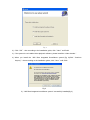
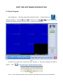
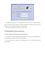
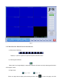
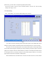
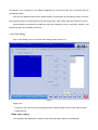
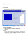
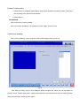
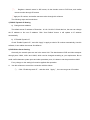
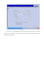
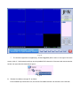
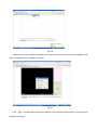
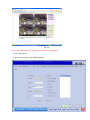
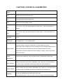
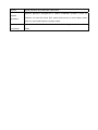
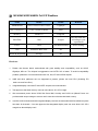
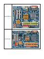
JMV Video Surveillance
User Manual
Shenzhen Jim Video Technology Co., Ltd.
All right reserved
July 9th,2009
Ver:01.01.04
Note
Thank you for buying our product.
Before using this surveillance system, please read the user manual carefully to familiar with
their functions. Otherwise, we will not responsible for any consequence.
This User Manual will tell you the installation, operation, setting and networking of Jimvise
Surveillance system in detail.
The host’s working voltage is 220 volts (10% more or less). Thus, in the bad situation, to
insure the normal work of system, please use uninterruptible power system (UPS).
When install or remove the DVR card, please be sure that the electricity is cut off, and the
mainboard is completely de-energized.
D1 and CIF resolution can be switched, but after setting in the resolution, it can only work
after you close and open the channel again.
The working temperature is from -10±3℃ to 55±2℃, and the environment should be clean
and well-ventilated.
We have patent on this software. Copy is not allowed without our consent. For the copy
software, we are not responsible for the stable and will affix the responsibility through relevant
legal.
Features(H.264 Compression)
¾
Compression:H.264/MPEG 4;
¾
Display resolution:1024×768、1280×1024、16:9 widescreen、16:10 widescreen;
¾
Preview resolution(adjustable) :704×576(PAL),740×480(NTSC);
352×288(PAL),370×240(NTSC);
¾
Video resolution:704×576(PAL), 740×480(NTSC);
352×288(PAL),370×240(NTSC);
¾
One PC can install multiple cards and have up to 12 channels full D1 or 48 channels full CIF
¾
Support one to 36 picture display in one screen, full screen display, auto flip
¾
Display/Record/Playback multi-channels in one screen; Support multiple PTZ control and alarm
boxes to realize linkage alarm
¾
Various recording modes: continuous recording, scheduled recording and motion triggered
recording
¾
Each camera’s name can be set as you like
¾
Support video source in PAL and NTSC format. 25fps for PAL format to realize real time record and
playback
¾
Video images adjustment make the image more clearly
¾
Multi levels of quality available. Higher level provides clear images and bigger files.
¾
Motion alarm record and sound alarm output, adjustable alarm record sensitivity, adjustable time for
scheduled record and delay record
¾
Intelligent retrieval, user can select playback files according to its Date, Channel, and Recording
mode. The system will auto list all the eligible files that matches users specifications.
¾
With functions of local amplifier and playback by frame; user can choose the display mode: rapid,
slow or regular
¾
The user can snapshot, backup and edit the playing file
¾
Support remote Surveillance, remote control the lens, color, manual record, and computer restart
¾
One PC can install multi hard disks with the maximum capacity
¾
The hard disk can be fully used trough the maximum and minimum setting
¾
Automatically create the log file (user operation log, system log, remote control log)to facilitate query
operation
¾
User can set the system shutdown and restart time arbitrarily
¾
The surveillance system can be set to automatically start each time windows starts-up and
shutdown when power off. When power on, the system will restart and recover video automatically.
¾
Reliable hardware and stable software
¾
Low hardware requirements, 48 channel’s recording occupy only 75% CPU
¾
System can effectively prevent system brush caused by repeated operation
Contents
CHAPTER 1 SOFTWARE INSTALLATION .....................................................................................6 1.1 System Requirements .................................................................................................................................. 6 1.1.1 Hardware Requirements ................................................................................................................... 6 1.1.2 Software Requirements..................................................................................................................... 6 1.2 Software Installation.................................................................................................................................... 6 1.3 Software Uninstallation ............................................................................................................................... 8 PART TWO SOFTWARE INTRODUCTION.....................................................................................9 2.1 Enter Program.............................................................................................................................................. 9 2.2 Software Main Interface Introduction........................................................................................................ 10 2.2.1 JMV iSee Integrated Monitoring System Main Interface ............................................................... 10 2.2.2 Main Interface Button Function Introduction ................................................................................. 11 2.3 Software Setting ........................................................................................................................................ 15 2.3.1 Basic Setting ................................................................................................................................... 16 2.3.2 Record Setting ................................................................................................................................ 18 2.3.3 Video & Audio Setting.................................................................................................................... 19 2.3.4 PTZ Setting..................................................................................................................................... 20 2.3.5 Alarm Setting .................................................................................................................................. 22 2.3.6 Color Setting................................................................................................................................... 23 2.3.7 Motion Detection ............................................................................................................................ 24 2.3.8 Privacy masking.............................................................................................................................. 25 2.3.9 Display Setting................................................................................................................................ 26 2.3.10 Storage setting............................................................................................................................... 27 2.3.11 System setting ............................................................................................................................... 28 2.3.12 Network setting............................................................................................................................. 29 CHAPTER 3
PLAYBACK ...........................................................................................................36 CHAPTER 4 TECHNICAL PARAMETERS....................................................................................38 Appendix I: The Recommendation for DVR Card ............................................................................41 Ⅰ. 4CH/8CH/12CH Full CIF Realtime .......................................................................................................... 41 Ⅱ. 4CH/8CH/12CH Full D1 Realtime............................................................................................................ 41 Ⅲ. 16CH/24CH/32CH/48CH Full CIF Realtime............................................................................................ 42 Hardware ................................................................................................................................................. 42 Software................................................................................................................................................... 43 Appendix II: List of Recommended Motherboard.............................................................................43 CHAPTER 1 SOFTWARE INSTALLATION
1.1 System Requirements
1.1.1 Hardware Requirements
Motherboard
Intel G31/G35 chipsets,2 or more PCI-EXPRESS slots
CPU
Intel Core E4300 (Core(TM)2 E5200 is recommended)
Memory
512M(Recommended dual memory)
Display card
Integrated graphics card
Network
10/100M
Resolution
1024*768,1280*1024,support widescreen
1.1.2 Software Requirements
Operation system:Windows 2000/Windows XP/Windows Vista
1、Recommended operation system: Microsoft Windows XP Professional sp3
2、Install DirectX 9.0 or above
3、Use the latest card driver
4、Please do not install a firewall, antivirus software or other applications on the host which install
the DVR software. (Firewall, including system firewalls can cause remote access connection failure;
antivirus software occupy the system resource, thus may affect the stability of DVR software;
please don't run other applications when DVR software running.)
Note: To insure the normal work of DVR please install motherboard driver before the installation of
video driver.
1.2 Software Installation
1) Double-click Setup.exe to start the installation, fig 1:
Fig 1
2) Click“OK”
,then according to the installation guide, click“Next”until finish
3) If the system is not installed video playback software, please install the “video decoder ”
4) When you install the “JMV iSee Integrated Surveillance system”,(fig 2)Click “ Continue
Anyway”,then according to the installation guide, click“Next”until finish
Fig 2
5) “JMV iSee integrated surveillance system” successfully installed(fig 3)
Fig 3
1.3 Software Uninstallation
1)Mode 1:Click Start > Procedures-> iSee ->Uninstallation, Uninstall the software will delete the related
documents, but keep DVR video files and folders.
2)Mode 2:Open “control panel”,then double-click “
” to find “iSee DVR”,click
“cancel”on the lower right corner, then according to the installation guide, click“Next”until finish
PART TWO SOFTWARE INTRODUCTION
2.1 Enter Program
After installing the “JMV iSee Integrated Surveillance System”, double-click the icon “
” on
Windows desktop or click Start->Program->Jim Video Tech, Ltd-> iSee-> iSee to open "JMV iSee
Integrated Surveillance System” preview screen, no need to input password.
Fig 4
All buttons are locked after entering the main interface of “JMV iSee Integrated Surveillance
System”, click “
”or any other button, a window will show as fig 5
Fig 5
Click “Y”, and a window will show as fig 6, and then input admin into User name and Password.
Fig 6
After login successfully, enter “User Setting”, add new user name, and do “Authority Setting” to
protect some common users to change the settings. Administrator has authority to create, delete and
manage new users. See detailed information in “Authority Setting”
Note: System administrator name: admin, password: admin.
2.2 Software Main Interface Introduction
2.2.1 JMV iSee Integrated Monitoring System Main Interface
Before running “JMV iSee Integrated Monitoring System”, make sure your computer display 32-bit
true color resolution, resolution ration 1024*768 or 1280*1024.
(It is recommended to use 1280*1024 for a display larger than 17” as it will be larger and clearer
when browsing)
Fig 7
2.2.2 Main Interface Button Function Introduction
1) Multi-picture Switching
Display in 1 picture /4 picture /16 picture /25 picture and full screen
2) Rearrangement Button
When there is no image display in sequential windows, this button can help rearrange all windows
with images in order.
3) Page button
Page down
Page up
When one page cannot display all monitoring screens, click “
” to enter next page, and click
“
” to enter previous page.
4) Page Cycling Button
Click, pages will sequentially display in order according to previous time setting. (See detailed
in “Global Setting”)
5) Playback Button
Click, it will enter video playback screen
6) Configuration Button
Click to enter program configuration screen.
Note: only administrator and senior user can use this function.
7) Help Button
Click, “JMV iSee Integrated Monitoring System” User Manual,
8) Lock Button
Click, it will lock current screen, and show the unlock window as fig 8:
Fig 8
When locked, there is no response to click any button. This will effectively avoid that when
monitoring person leave, other people do wrong operations to system. It will unlock after input login
password.
9) Minimize Button
Click, JMV iSee Integrated Monitoring System will minimize in taskbar, and it will be back to
Windows screen.
10) Hardware Device List
Fig 9
Show current PCI-EXPRESS video capture card device status in host computer.
11) Open Button
Choose one camera in device list, and click “
” to open current video.
12) Recording Button
Choose one camera in device list, and click “
13) Stop Recording Button
” to start current video recording manually.
Choose one camera in device list, and click “
” to stop current video recording.
14) Close Button
Choose one camera in device list, and click “
” to stop current video recording.
15) Snapshot Button
Choose one camera or click one monitoring screen in device list, and click“
” to snapshot the
selected screen. The snapshot picture will be stored by JPG format, and the storage location can
be modified in “Storage Setting”.
16) Zoom Button
:Lens zooms in
:Lens zooms out
17) Iris Button
:Lens iris zooms in
:Lens iris zooms out
18) Focus Button
:Lens focus far
:Lens focus near
19) PTZ Control Button
:P/T/Z up
:
:P/T/Z down
:
P/T/Z left
P/T/Z right
:P/T/Z light on/off switch
:P/T/Z blow switch
:P/T/Z preplace position setting button; click, and input the preplace position number to set
P/T/Z preplace position.
:P/T/Z preplace position call button; click, and input the the preplace position number to call
P/T/Z preplace position.
20) Exit Button
Click “
” to exit JMV iSee Integrated Monitoring System”
2.3 Software Setting
Click “
” to enter the program setting screen, see fig 10:
Fig. 10
Click the list in the right to choose channel and do the settings for each channel.
2.3.1 Basic Setting
Click “Basic” icon to enter into basic parameters setting, seen in fig. 11:
Fig 11
Camera Name: name the selected camera
Camera type: Local DVR or remote DVR
IP Address: This software can connect IP camera and the user can input the IP address of the IP
camera.
Connection way: Display whether it is the local device
Camera description: Input a text description for the selected camera
Activate this device when JMV iSee system is open:
Check the box, this video channel will open automatically when “JMV iSee
Integrated Monitoring System” start.
Otherwise not
Start recording when the device is open:
Check the box; start recording automatically when the video is open.
Otherwise not
Support remote monitor:
Check the box, the video support remote monitor
Otherwise not
Apply to all:
Check the box, the setting of other all video channels will be the same as the current video channel
Otherwise not
Use Default
Click it will return to factory setting
After you change the setting, it is necessary to click “Apply” button to save.
2.3.2 Record Setting
Click “Record” icon to enter the record setting screen, see fig 12:
Fig 12
Apply to all:Check the box, the setting of all video channels will be the same as the current video
channel
Otherwise not
Scheduled Record: There are three scheduled record modes to choose:
①Once: Define the recording time for any recording file
②A week: User can set the record time (from Monday to Sunday)
③24/7: The camera will record all time
Use Default
Click it will return to factory setting
After you change the setting, it is necessary to click “Apply” button to save.
2.3.3 Video & Audio Setting
Click “Video & Audio Setting” icon to enter video and audio setting, see fig 13:
Fig 13
Apply to all:Check the box, the setting of all video channels will be the same as the current video
channel
Otherwise not
Video Encoder Setting
→ Video Compression: H.264/MPEG4
→
Optimized Encoder: there is three choices-super high quality, high quality and high speed.
→
Super high quality—the image is best with video not compressed, the CPU occupancy a bit
higher, and the recording file disk is not limited. It is mainly used in such fields as Bank, Financials
and Government etc. with high requirements.
→
High quality—the image is in high quality, and the recording file disk is limited: D1 resolution
40-640M/H/C, and CIF resolution 10-200M/H/C. It is fit for common situation.
→
High speed—when computer dominant frequency is low, it is recommended to choose high
speed.
Audio Encoder Setting
→
Audio Compression: G.711/Speex
→
Audio Compression Quality: set it to low, normal, or high
Video Setting
→
Frame Rate: set the frame rate for the selected channel (PAL: 1-25 fps NTSC: 1-30 fps)
→
Video Mode: PAL/NTSC
→
PAL resolution: 352*288(used in China mainland)
→
NTSC resolution: 352*240
※ Note: specific setting depends on the camera
Resolution setting
Resolution: D1 or CIF
→
Choose D1, the video will display, record and playback in D1 resolution
→
Choose CIF, the video will display, record and playback in CIF resolution.
Every time when resolution is changed, it is necessary to close the corresponding video first, and
then open the video again. Note it is a must.
Use default
Click it will return to factory setting
After you change the setting, it is necessary to click “Apply” button to save.
2.3.4 PTZ Setting
Click “PTZ Setting” icon to enter the PTZ setting screen, see fig 14:
Fig 14
1. PTZ Setting
Start PTZ:
Check the box to start PTZ and do setting for PTZ protocol, COM, port, Baud Rate and PTZ address
if the device has PTZ function
Otherwise not
PTZ Protocol: Decode protocol for decoder. This software has installed main internet protocols,
such as, PELCO-D,PELCO-P,SUMSANG etc.
COM port: the port number to connect the decoder set for the selected channel. Default Is COM1.
Baud Rate: the decoder baud rate set for the selected channel; there is 2400/4800/9600/19200 for
selection.
PTZ Address encodes: the value is set in the front-end PTZ decoder.
2. PTZ preplace position setting
Control the PTZ to appointed address through the PTZ button. Input the PTZ number in the text of
“set PTZ preplace position”, and input the description information in the text of “set PTZ preplace
position name”, and click “Add” to complete PTZ preplace position setting.
Input the PTZ number in the text of “call PTZ preplace position”, and click “call”. After the setting
changed, click “Apply” to save.
2.3.5 Alarm Setting
Click “Alarm Setting”icon to enter the alarm setting screen, see fig 15
Fig 15
If you need to connect the monitoring system with the alarm system, check “Enable alarm” and do
settings for recording, snapshot, call preplace position and reminding sound etc. to ensure the safety.
Port number: when the monitoring system connect with the alarm system, the alarm signal transfer
from the alarm device through the computer port number (COM port) to the alarm system. Choose the
COM port not occupied, as there is a default COM port in computer. If the default port has been used in
PTZ 485 signal transfer, it is necessary to add port number to add computer COM port. It can avoid the
signal intersect caused PTZ uncontrolled or disabled alarm.
Warner addresses code: It is the alarm device. If there are more than one device, in order to distinct
the devices, it is necessary to set different addresses for all devices that has connected with the
monitoring system.
Port rate: the default speed rate for digital transfer is 2400 when the monitoring system connects
with the alarm system. All alarm devices can set the port rate, 2400, 4800, 9600 and 19200 for choices.
Alarm handling: the monitoring system can react when alarming, such as, recording, snapshot, call
preplace position and reminding sound etc.
2.3.6 Color Setting
Click "Color Setting" icon to enter the basic setting screen, see fig 16:
Fig 16
Apply to all
¾ Check the box, other all video channels will be the same setting as the current video channel.
¾ Otherwise not
Video color setting
You can adjust the brightness, contrast, chroma and saturation degree to the selected
video.
Use default
Click it will return to factory setting.
After you change the setting, it is necessary to click “Apply” button to save.
2.3.7 Motion Detection
Click “Motion Detection” icon to enter the motion detection setting screen, see fig 17:
Fig 17
Enable video motion detection
¾ Check the box to enable video motion detection for the selected video
¾ Otherwise not
Sensitivity
¾ There are 3 choices to set the sensitivity of video motion detection---high, medium and low.
¾ The least seconds for recording when detecting moving objects in the video: Time for
recording after the moving objects stop in the video.
Enable E-mail sending
¾ Check the box to enable E-mail sending. After motion detection recording finished, it will send
the recording to the preset E-mail address.
¾ Otherwise not
Use default
Click it will return to factory setting.
After you change the setting, it is necessary to click “Apply” button to save.
2.3.8 Privacy masking
Click “Privacy Masking” icon to enter the video mask setting screen, see fig 18
Fig 18
This setting is mainly used in such fields as Banks and plots etc. which are not convenient to
monitor. Check “Enable video mask”, click the mouse left key and draw the area need to mask in the left
video preview screen, and then click “Apply”.
2.3.9 Display Setting
Click “Display” to open “Display Setting”(fig 19):
Fig 19
Display Mode
○ Direct Draw(Default):
○ Direct 3D:
○ GDI:
Any change to this function, it is a must to restart the software.
Pages Cycling Interval
Click “
”(page cycling button) to set Interval time for pages cycling, the default time is 10
seconds.
Default Display Video Channels
The number of display screens when start “JMV iSee Integrated Surveillance System”
OSD Setting
□Time Display:
Check the box to display time and date in the screen
Otherwise, it will not display time and date in the screen
□
Display
Device
Name
:
Check
the
box
to
display
the
preset
device
Otherwise, it will not display the preset device name
□Animation Display When Alarming: Check the box, the screen will become full screen
from a small screen and flickering when alarming
Otherwise, no response in the screen when alarming
Use default
Click it will return to factory setting.
After you change the setting, it is necessary to click “Apply” button to save.
2.3.10 Storage setting
Click “Storage” to enter storage parameters setting, seen in fig. 20:
name
Fig. 20
Disk Volume
Show current number of disks, total volume and free space etc on the host computer. To keep the
system stable, it is better not set disk C as storage disk. The default storage disk is disk D, and you can
set other disks as the storage disk manually.
Storage Rule
The storage disks are limited; you can choose below settings in the software when free space is
lower than the defined minimal disk space.
① Delete old files
② Stop recording
③ Reminding sound
Snapshot files storage path: click“Browse”button to select a path to save the snapshot pictures.
2.3.11 System setting
Click “System” icon to open system setting screen, seen in fig. 21:
Fig. 21
□Auto running the software when power on: Check the box, the “JMV iSee Integrated Surveillance
System” will start automatically when computer power on.
Otherwise not
□Auto shutdown when software closed: Check the box, the computer will shutdown automatically when
“JMV iSee Integrated Surveillance System” closed.
Otherwise not
Use Default
Click it will return to factory setting
After you change the setting, it is necessary to click “Apply” button to save.
2.3.12 Network setting
Click “Network Setting” icon to open the network setting screen, see fig 26:
Fig. 22
The server is set up and there 2 ways to do WAN remote monitor:
①
Register a domain name in JMV server, tie the domain name to DVR host, and realize
remote monitor through IE browse.
②Apply an ID number, and realize remote monitor through this software.
The following steps are introductions:
1) DDNS / Dynamic IP Setting
a) Change server address
The default server IP address of Shenzhen . is 219.136.240.51.Check the box, the user can change
the IP address to his own IP address. Click “Use Default” button. It will update to IP address
automatically.
b) IP Enable Dynamic IP
Check “Enable Dynamic IP”, and click “Apply” to apply a serial of ID number automatically, Use this
software, it can realize the remote Surveillance.
2) DVR Video Server Setting
Generally, the network ports are set in the same LAN. The data between DVR and client transport
through ports 10060, 10061 and 10062, which can be changed according to your requirement. But to
avoid conflict between system ports and other procedure ports, it is better to set the ports above 9000.
Every change on the setting info must be applied after operation.
A.
Use this software to control the connection with the clients:
①
Click“Enable dynamic IP”,and then click“Apply”, the user can get an ID number:
Fig. 23
② click“Device” on the right equipment list,this option enables user to add device from other LAN
or Internet. Click“Add Remote”,and then choose Internet, input the ID number applied just now. Save
the password, and click “OK”.
Fig. 24
③
The internet equipment we applied(e.g. DVServer@2288) will be seen on the right of the main
screen, click of “+”before device will pop out the possible DVR channels. If the user need remote monitor
he/she can right click the channel and open it.
Fig. 25
B.
Remote Surveillance through IE, as follow:
Enter website http://www.hidvr.com, the remote Surveillance button can be seen on the left side.
Fig. 26
Install Activex control software according to the guide. After that, input the ID number applied, user
name and password for connection, see fig 27:
Fig. 27
Click “
”to enable client’s remote Surveillance for the selected channel when it is connected to
the server, see fig 32
Fig. 28
Note:Only senior user can change the configuration of this page.
2.3.10 User setting
3. Click “User” to open “User Setting”(fig 29):
Fig. 29
If this is the first time for you to use our software please enter “Setting”, set operators and their
permissions to prevent normal user login with administrators account, causing unnecessary losses.
Administrators have the supreme authority to add, delete, manage the user etc.
Click“
”on the below of equipment list to add a new user:
User Name:input the name and code of the new user
Password:set the password for the new user
Repeat the password: input the password again for verification
Description(optional):add related description for the new user, e.g.:Manager of security
department, Security guard captain、security guard etc.
Email(optional):it is recommended to write your email add if you have ,as the system will send
alarm information such us image to your email
Select needless user name, click the button“
”below equipment list box to delete this user.
Every change on the user info must be saved after operation.
CHAPTER 3
Click on
PLAYBACK
,to enter video playback,(Fig.30):
Fig.30
Video file display: the default is nine-picture display, the user can adjust for 16-picture display,
25-picture display or full screen. Single left-click any display window to have a full screen view on the
current channel. When a window is selected, then there is a red box around. The selected window is
called broadcast window.
On the right of the main screen, user can select playback files according to its Date, Channel, and
Recording mode. Any video file matches will be showed in blue on the 0—23 time axis, just single click
and drag the slider to the specified period of time to display the video file
Play function keys (Play, Fast forward, Fast backward, Stop and Backup) are located at the bottom
right corner.
Play
Pause
Stop
Snapshot
Backup
Fast backward the image
Fast forward the image
Step backward by 10 seconds
Step forward by 10 seconds
CHAPTER 4 TECHNICAL PARAMETERS
Model
O/S
Windows XP PRO (recommended)
V/I
Multi-channel PAL/NTSC video input
V/O
Support secondary display device
8/16 channel(open and closed optional)alarm input,can be extended to 32
A/I
channel
8/16 channel(open and closed optional)alarm output,can be extended to 32
A/O
channel
Interface
RJ-45
Resolution
352*288dpi (PAL)、352*240dpi (NTSC)
Real time display, one-picture display/four- picture display/six-picture
display/eight-picture display/nine-picture display/ten-picture display/twelve-picture
Display Mode
display/sixteen-picture display/twenty-picture display/twenty-five-picture
display/sixty-two-picture display/full screen display, Locking, security and picture
switching function
Image
Camera name, date/time, video and alarm status, confidential covered area
Information
Display current time and position adjustable) :X(0—180),Y(0—270),save them in
Time Indicator
the video images. Adjustable time display brightness and transparency
Display camera name and position adjustable) :X(0—180),Y(0—270),save them in
Camera Name
the video images. Adjustable time display brightness and transparency
Shielding
Two size of shielding area:128*64 and 64*32; save
position(adjustable(0—220),Y(0-220) in the video images; adjustable shielding
background color
Continuous record, scheduled record, alarm linkage record, detection record, hard
Record Mode
disk overwrite record, auto record when power on
Video Quality
Set the image quality to be best, better, normal, bad or worst
Compression
H.264
Video Medium
Hard disk with capacity unlimited
Retrieval and display according to the time; playback many pictures in one screen,
Retrieval
playback by frame, quick playback, slow playback, single screen amplification,
playback
partial enlargement, single image saving, remote playback
Backup
Backup to other hard disk or CD, DVD
With RS - 232 terminals connect to the decoder by 485 communication to control
PTZ Control
the PTZ
Dynamic
perception
99 perceptual area and 9 sensitivity levels for the user to set; adjustable record
time, support scheduled record
Glass broken alarm, infrared alarm, vibration alarm, signal loss alarm, alarm signal
Alarm mode
upload, linkage alarm and multiple output , alarm continuous record and output
time adjustable
E-map
Alarm automatically pop-up e-map, 36 alarm area can be arbitrarily set
Upload mode
Help signal upload, open signal upload, alarm event upload
Remote
PSTN、ISDN、ADSL、DDN、INTENET、OPTICAL FIBER
network
connection
Real-time monitoring, remote playback, remote record, remote PTZ control,
Networking
remote video regulation
Remote alarm
Image reminder and sound alarm
Remote
Remote control air conditioning, entrance, lobby lamp, advertisement lamp,
control
remote shutdown and restart the outlet server
Multilevel password management to realize unattended operation: power off
system
shutdown can save all record files; restart and recover to record status when
protection
power on; auto restart when the system closed
Seamless
Replace video files with seamless connection technology, to ensure the video
connection
quality
Appendix I: The Recommendation for DVR Card
Jim Video Call Your Attention: Our strict test approves that Jim Video’s DVR Card work stably
with recommended hardware. Jim Video advises you to select the recommended hardware, to eliminate
system instability.
Ⅰ. 4CH/8CH/12CH Full CIF Realtime
Name
Model
Brand
Remark
Motherboard
GA-G31M-S2L /GA-G31MX-S2
Gigabyte
CPU(including fan)
Intel Core 2 E 4300 or better
Intel
Memory
DDR2 512M 以上
Kingston
Hard Disk
250G
Seagate
Buy the hard disk
according to your
requirement
Power
250W
GreatWall/HuntKey
Power Rating
Case
Industrial 400L/450L
No
Mouse &
Keyboard
Average
No
Ⅱ. 4CH/8CH/12CH Full D1 Realtime
Name
Model
Brand
Remark
Motherboard
GA-G31M-S2L /GA-G31MX-S2
Gigabyte
CPU(including fan)
Core 2 E 5200 or better
Intel
Memory
DDR2 512M×2
Kingston
Better effect with
dual memory
Hard Disk
320G
Seagate
Buy the hard disk
according to your
requirement
Power
300W
GreatWall/HuntKey
Power Rating
Case
Industrial 400L/450L
No
Mouse &
Keyboard
Average
No
Ⅲ. 16CH/24CH/32CH/48CH Full CIF Realtime
Name
Model
Brand
Motherboard
GA-G31-S3G/ GA-G31-S3L
Gigabyte
CPU(including fan)
Core 2 E5200 or better
Intel
Memory
DDR2 1G
Kingston
Remark
Hard Disk
320G
Seagate
Buy the hard disk
according to your
requirement
Power
350W
GreatWall/HuntKey
Power Rating
Case
Industrial 400L/450L
No
Mouse & Keyboard
Average
No
Hardware
1.
Please use famous brand motherboard with good stability and compatibility, such as ASUS,
Gigabyte, MSI etc. The chipset is suggested to use INTEL 915 or better. To avoid incompatibility
problem, please do not use mainboard with VIA, SIS, ATI and nVIDIA chipset.
2.
AMD and other platforms are not supported at present, please use Intel CPU (including PD
dual-core and Core Duo).
3.
Integrated display card with ATI and INTEL chipset are recommended.
4.
Test approves that dual memory card can save about 10% CPU usage.
5.
We recommend power above 350W, like Great Wall, Huntkey and COOL etc (Brand Power can
provide stable output voltage to ensure card’s normal work and avoid black screen).
6.
Intel G31/G35 motherboard with integrated display card are recommended with Surveillance system
less than 48 channels.(Our test approves that integrated display card can save about 10% CPU
usage than alone display card)
Software
1.
Microsoft Windows XP Professional sp3 system is recommended, do not support Win9x and server
version.
2.
Install directx 9.0c or above.
3.
Using the latest video driver to get better effect.
4.
Please do not install a firewall, antivirus software or other applications on the host which install the
DVR software. (firewall, including system firewalls can cause remote access connection failure;
antivirus software occupy the system resource, thus may affect the stability of DVR software; please
don't run other applications when DVR software running.)
5.
To insure the normal work of “JMV software” please install mainboard driver before the installation of
video driver.
Appendix II: List of Recommended Motherboard
In order to save cost and obtain the optimum performance, it is recommended to use motherboards
with integrated display card and Intel 945 chipset. Try to choose motherboard with more PCI-Express
slots, as Jim Video DVR cards are designed to based on PCI- Express 1X interface, equally applies to
the PCI Express - 4X / 8X / 16X slots.
Recommended Motherboard List
Intel Chipset 945
Gigabyte
GA-945PL-S3P
G31 Motherboard
Gigabyte G31 series
Model
GA-G31-S3G
GA-G31M-S2L
Picture
GA-G31MX-S2
GA-G31-S3L
SHENZHEN JIM VIDEO TECHNOLOGY CO.,LTD
Add:RMB504,Techonology Innovation International,10th Block of Tech South RD,Nanshan,
Shenzhen, Guangdong, China
Website: www.JMV-tech.com
TELL: +86-755-86377041
FAX: +86-755-86377040