1
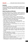
Multi-system Scanner Series User's Manual
Disclaimer
All information, illustrations, and specifications contained in this
manual are based on the latest information available at the time
of publication. The right is reserved to make change at any time
without notice.
EN
Safety Precautions and Warnings
To prevent personal injury or damage to vehicles and/or the
Multi-system Scanner, please read this user’s manual first
carefully and observe the following safety precautions at a
minimum whenever working on a vehicle:
•• Always perform automotive testing in a safe environment.
•• Do not attempt to operate or observe the tool while driving
a vehicle. Operating or observing the tool will cause driver
distraction and could cause a fatal accident.
•• Wear safety eye protection that meets ANSI standards.
•• Keep clothing, hair, hands, tools, test equipment, etc. away
from all moving or hot engine parts.
•• Operate the vehicle in a well-ventilated work area: Exhaust
gases are poisonous.
•• Put blocks in front of the drive wheels and never leave the
vehicle unattended while running tests.
•• Use extreme caution when working around the ignition
coil, distributor cap, ignition wires and spark plugs. These
components create hazardous voltages when the engine is
running.
•• Put the transmission in P (for A/T) or N (for M/T) and make
sure the parking brake is engaged.
•• Keep a fire extinguisher suitable for gasoline/chemical/
electrical fires nearby.
•• Don’t connect or disconnect any test equipment while the
ignition is on or the engine is running.
•• Keep this tool dry, clean, free from oil/water or grease. Use a
mild detergent on a clean cloth to clean it if necessary.
I
Multi-system Scanner Series User's Manual
Table of Contents
1 INTRODUCTION...........................................................1
2 Product Descriptions..................................................2
2.1 Outline of Multi-system Scanner.............................2
2.2 Specifications.........................................................3
2.3 Accessories............................................................3
2.4 Product Troubleshooting.........................................3
2.5 Power supply..........................................................4
3 Tool Setup....................................................................5
3.1 Connection.............................................................5
3.2 Tool Setup...............................................................6
3.3 Tool Information......................................................7
4 Diagnose......................................................................8
5 Upgrading.....................................................................10
6 FAQ...............................................................................13
II
Multi-system Scanner Series User's Manual
1 INTRODUCTION
The Multi-system Scanner Series covers the following models:
Multi-system Scanner i980, Multi-system Scanner i960, Multisystem Scanner i930, Multi-system Scanner i906, Multisystem Scanner i908 and Multi-system Scanner i902, which is
especially designed for the DIY users and the servicemen of
small service workshop.
EN
Featuring the color LCD display and personalized function
menu, the Multi-system Scanner Series can diagnose full
electronic control system of single vehicle model.
The wording “OBDII/EOBD” (refer to Figure 1-1) marked on
the back of the Multi-system Scanner Series defines OBD
connector, instead of OBDII/EOBD functions.
Figure 1-1
Note: The MULTI-SYSTEM SCANNER may automatically reset
while being disturbed by strong static electricity. THIS IS A
NORMAL REACTION.
1
Multi-system Scanner Series User's Manual
2 Product Descriptions
2.1 Outline of Multi-system Scanner
2
1
10
3
4
9
8
7
6
5
Figure 2-1
2
1 Power Indicator
Lights up when your tool is
powered on.
2 Cable with OBD II
Connector
Connects the Multi-system
Scanner to the vehicle’s Data Link
Connector (DLC).
3 LCD Display
Indicates test results.
4/7 UP/DOWN Button
Move cursor up or down for
selection.
5 OK Button
Confirms a selection (or action)
from a menu list.
Multi-system Scanner Series User's Manual
6/8 RIGHT/LEFT Button
Move cursor right or left for
selection; Or turn page up or
down when more than one page
is displayed.
9 USB Port
Connects to computer to update
the Multi-system Scanner.
10 ESC Button
Returns to previous menu.
EN
2.2 Specifications
1) Screen: 2.8” TFT 262K true color, 320*240dpi
2) Input voltage range: 9~18V
3) Operating current: <100mA@12V (Typical)
4) Power consumption: <1.2W (Typical)
5) Operating temperature: 32°F~122°F / 0°C~50°C
6) Storage temperature: -4°F~158°F / -20°C ~70°C @ RH60%
7) Outline dimension: 4.7’*3.2’*1.0’ / 121*82*26 mm (L x W x H)
8) Weight : < 500g
2.3 Accessories
1) User’s Manual -- Instructions on tool operations
2) USB cable -- Connect to a computer for upgrading online
2.4 Product Troubleshooting
Vehicle Linking Error
A communication error occurs if the scan tool fails to
communicate with the vehicle’s ECU (Engine Control Unit). You
3
Multi-system Scanner Series User's Manual
need to do the following to check up:
A) Verify that the ignition is ON;
B) Check if the scan tool’s OBD II connector is securely
connected to the vehicle’s DLC;
C) Verify that the vehicle is OBD2 compliant;
D) Turn the ignition off and wait for about 10 seconds. Turn
the Ignition back to on and continue the testing;
F) Verify the control module is not defective.
Scan tool doesn’t power up
If the scan tool won’t power up or operates incorrectly in any
other way, you need to do the following to check up:
A) Check if the scan tool’s OBD II connector is securely
connected to the vehicle’s DLC;
B) Check if the DLC pins are bent or broken. Clean the DLC
pins if necessary.
C) Check vehicle battery to make sure it is still good with at
least 9.0 volts.
2.5 Power supply
The power of the Multi-system Scanner is provided via the
vehicle’s Data Link Connector (DLC). Follow the steps below to
power it up:
1) Find DLC on vehicle;
Note: A plastic DLC cover may be found for some vehicles
and you need to remove it before plugging the OBDII cable.
2) Plug the connector at the end of OBD II cable to the
vehicle’s DLC.
4
Multi-system Scanner Series User's Manual
3 Tool Setup
3.1 Connection
1) Turn the ignition off.
2) Locate the vehicle’s 16-pin Data Link Connector (DLC).
EN
The DLC (Data Link Connector) is the standardized 16-cavity
connector where diagnostic code readers interface with the
vehicle’s on-board computer. The DLC is usually located 12
inches from the center of the instrument panel (dash), under
or around the driver’s side for most vehicles. If Data Link
Connector is not located under dashboard, a label should be
there telling location. For some Asian and European vehicles,
the DLC is located behind the ashtray and the ashtray must be
removed to access the connector. If the DLC cannot be found,
refer to the vehicle’s service manual for the location.
Figure 3-1
3) Plug the OBDII cable into the vehicle’s DLC.
4) Turn the ignition on. Engine can be off or running.
5) After finishing, press [OK] button to enter Main Menu.
5
Multi-system Scanner Series User's Manual
Figure 3-2
CAUTION: Don’t connect or disconnect any test equipment
with ignition on or engine running.
3.2 Tool Setup
This option enables you to change your interface language and
turn the beeper on/off.
Select [Tool Setup] in the Main Menu and press [OK] to enter.
Figure 3-3
1) Language: To swtich to the desired language.
Choose [Language] and press [OK] to enter. Use [ ] / [ ] key
to select any language and press [OK] to confirm, the system
will switch to the chosen language interface.
6
Multi-system Scanner Series User's Manual
2) Beeper: To turn the Beeper ON/OFF.
Choose [Beeper] and press [OK] to enter. Use [ ] / [ ] to select
ON/OFF and press [OK] to confirm.
3.3 Tool Information
EN
This option allows you to view: boot version, display program
version, diagnostic program version, serial number and register
code.
Figure 3-4
Press [ESC] to return to the previous screen.
7
Multi-system Scanner Series User's Manual
4 Diagnose
This function is specially designed to diagnose electronic control
system of single vehicle model.
Figure 4-1
Refer to the flowchart illustrated as below to diagnose a vehicle:
8
Multi-system Scanner Series User's Manual
Note: For vehicles manufactured by different vendors, it
is possible that it has different diagnostic menus. For details,
please follow the instructions on the screen to proceed.
EN
9
Multi-system Scanner Series User's Manual
5 Upgrading
Follow the steps described as below to proceed registration and
update:
1. Go to http://www.icarsoft.com or http://www.icarsoft.us and
download the update tool to the computer.
2. Run the iCarsoft_Update_Setup.exe file, and follow the onscreen instructions to install the update tool (compatible with
Windows XP and Windows 7 operating system).
3.Launch the program when installed, a screen similar to
Figure 5-1 will appear:
Figure 5-1
4.In Figure 5-1, type in the Product Serial Number which is
located at the back of the tool.
5.After the serial number is entered, click Update to jump to
the registration page. Enter the following information and
click Submit.
10
Multi-system Scanner Series User's Manual
EN
Figure 5-2
(If you need the Register Code, please refer to steps 6~9.)
(If you have the Register Code, directly proceed to step 10.)
6.The Register Code can be found in your tool. Connect one
end of the supplied USB cord to your tool, and the other end
on the computer.
7.After the tool has powered up and entered the main menu
screen, move the highlight bar on the Tool Information and
press the [OK] button.
8.The Register Code shown in Figure 5-3 is the Register Code
needed in step 5.
Figure 5-3
(Return to step 5 and input the Register Code and then
proceed)
11
Multi-system Scanner Series User's Manual
9.Reopen the update tool, select the updates you would like
to perform, and then click Download to start downloading.
Figure 5-4
10.Once all steps are done, the registration process is
complete.
12
Multi-system Scanner Series User's Manual
6 FAQ
Here we list some frequently asked questions and answers
relating to Multi-system Scanner.
Question: System halts when reading data stream. What is the
reason?
EN
Answer: It may be caused by a slackened connector. Please
turn off the Multi-system Scanner, firmly connect the connector,
and switch on it again.
Question: Screen of main unit flashes at engine ignition start.
Answer: Caused by electromagnetic disturbing, and this is
normal phenomenon.
Question: There is no response when communicating with onboard computer.
Answer: Please confirm the proper voltage of power supply and
check if the throttle has been closed, the transmission is in the
neutral position, and the water is in proper temperature.
Question: Why are there so many fault codes?
Answer: Usually, it’s caused by poor connection or fault circuit
grounding.
Note: All pictures illustrated here are for reference and
demonstration purpose only and this User’s Manual is subject to
change without prior notice.
13