1
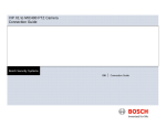
iVMS-7200 Installation Manual UD.6L0204A1064A01 Installation Manual of iVMS-7200 Thank you for purchasing our product. If there is any question or request, please do not hesitate to contact the dealer. This manual is applicable to iVMS-7200. This manual may contain several technically incorrect places or printing errors, and the content is subject to change without notice. The updates will be added into the new version of this manual. We will readily improve or update the products or procedures described in the manual. The figures shown in this manual are for reference only. The appearance and interface of the device are subject to the actual model. 1 Installation Manual of iVMS-7200 TABLE OF CONTENTS Chapter 1 Before you Start ......................................................................................................................... 3 1.1 Overview .................................................................................................................................................... 3 1.2 Running Environment ............................................................................................................................... 3 1.2.1 Hardware Environment...................................................................................................................... 3 1.2.2 Software Environment ....................................................................................................................... 4 1.3 Installation Environment Check List ......................................................................................................... 4 Chapter 2 System Introduction .................................................................................................................. 6 2.1 System Architecture ................................................................................................................................... 6 2.2 Network Connection .................................................................................................................................. 6 2.2.1 Front-end Device Connection ............................................................................................................ 6 2.2.2 Central Server Connection ................................................................................................................. 6 2.3 Bandwidth Calculation .............................................................................................................................. 7 2.3.1 Front-end Device Bandwidth ............................................................................................................. 7 2.3.2 Central Server Bandwidth .................................................................................................................. 7 2.3.3 Client Bandwidth ............................................................................................................................... 7 Chapter 3 Platform Installation and Configuration ................................................................................. 9 3.1 Platform Software Installation .................................................................................................................. 9 3.1.1 Web Installation ................................................................................................................................. 9 3.1.2 Servers Installation .......................................................................................................................... 14 3.1.3 OCX Installation ............................................................................................................................... 18 3.2 Front-end Device Configuration .............................................................................................................. 21 3.3 License Replacement ............................................................................................................................... 24 Chapter 4 Mobile Client Installation ........................................................................................................ 25 Appendix I Compatible Front-end Devices ................................................................................................ 26 Appendix II System Configuration Requirements .................................................................................... 27 Appendix III System Network Requirements ........................................................................................... 29 Appendix IV Server Loading Capacity ....................................................................................................... 30 Appendix V Enable NTP Service in Windows 2008 Server ...................................................................... 31 Appendix VI Enable Telnet Service in Win7 ............................................................................................. 32 Appendix VII Uninstall iVMS-7200 ............................................................................................................ 33 2 Installation Manual of iVMS-7200 Chapter 1 Before you Start 1.1 Overview Adopting multiple advanced technologies such as high-efficiency audio & video encoding technology, wireless transmission technology, GIS technology, mass data storage and search technology, the intelligent video management system iVMS-7200 provides powerful functionalities including real-time live view, remote playback, GPS location monitoring, system operating statistics, etc. Thanks to these features, iVMS-7200 is widely applied to the transportation industry and contributes to establish a comprehensive monitoring system combined with front-end devices including mobile DVRs, IP cameras, PVRs, etc. Table 1. 1 Description of Terms and Conventions Terms / Conventions Description CU Client Unit PU Producer Unit PPVSServer Register Server AlarmServer Alarm Server RSMServer Stream Media Server Windows Server 2008 R2 Front-end Device Operating system, SP1 patch is released on Feb. 23, 2011 DVR, Encoder, NVR, IP Camera, Mobile DVR, PVR, Mobile Enforcement System, etc. 1.2 Running Environment 1.2.1 Hardware Environment Server: Recommended: Processor: XEON 3440 @ 2.53G, Quad-core, 8M Motherboard: 3420GPLC Memory: 2*2GB DDR3 ECC HDD: 1*500G SATA Network Card: 1000Mps Router and Firewall The router and firewall should support the bidirectional mapping. Compatible Front-end Devices 3 Installation Manual of iVMS-7200 For details, see Appendix I Compatible Front-end Devices. 1.2.2 Software Environment Server Recommended: Operating System: Windows Server 2008 R2 Standard SP1 (64-bit Operating System) J2EE Server: Tomcat 6.0.18 Database Server: postgresql-9.2.4 Client Operating system: Microsoft Windows 7 Web browser: IE8, IE9, IE10, IE11 Firewall For the network security, hardware firewall is highly recommended for the system. During the firewall deployment, it is required to open the listening ports of the functional modules in the server. For details, see the table below. Table 1. 2 Open Ports of Firewall Server Register Server Alarm Server Stream Media Server Web Server Port No. Port Type Note 7660 UDP -- 7661 TCP Search server information 8000-10000 TCP Playback 7332 UDP -- 7280 TCP Search server information 7554 TCP Listening port 11000-15000 UDP Get stream from device via UDP 16000-18000 TCP Get stream from device via TCP 31000-35000 UDP Forward stream to platform client via UDP 31000-35000 TCP Forward stream to mobile client via TCP 80 TCP Default web service port Firewall opening ports should be modified accordingly if ports in configuration file are changed. 1.3 Installation Environment Check List Table 1. 3 Installation Environment Check List Check Items Criterion 4 Installation Manual of iVMS-7200 Hardware Fit to standard in the contract (CPU, Memory, HDD etc.). Software Fit to standard in the contract (OS requirement, iVMS-7200 Version) Front-end Device Device list in “Appendix I Compatible Front-end Devices” Firewall Configuration Ports opening meeting the requirements Network Connection Front-end device network connectivity; Central device network connectivity TCP/IP Configuration IP address, subnet mask, gateway and DNS in correct configuration 5 Installation Manual of iVMS-7200 Chapter 2 System Introduction 2.1 System Architecture The iVMS-7200 video management system platform consists of three modules: front-end devices, centralized servers and application clients. The front-end devices include the hardware equipment located in the vehicle, such as the mobile host, station reporter, microphone, camera, and emergency alarm button. The central servers and the application clients are composed of server hardware and iVMS-7200 platform client. The central servers get the data stream from the front-end devices, and the platform client communicates with the servers and transfers the collected information to the terminal users. Figure 2. 1 System Architecture 2.2 Network Connection 2.2.1 Front-end Device Connection The front-end devices can be connected to iVMS-7200 via wireless networks. 2.2.2 Central Server Connection The central server can be directly connected to the public network, and in this case each server requires for one public statistic IP address. You can also connect those servers to the public network via the router, and in this case, only one public statistic IP address is required for all the servers. 6 Installation Manual of iVMS-7200 2.3 Bandwidth Calculation The bandwidth for the surveillance system is related to the resolution and the frame rate. When the frame rate is 25fps, the bandwidths for different resolution are as follows: For CIF (Resolution 352×288), the bandwidth is 512Kbps; For 4CIF (Resolution 704×576), the bandwidth is 2Mbps; For 720P (Resolution 1280×720), the bandwidth is 4Mbps; For 1080P (Resolution 1920×1080), the bandwidth is 8Mbps. Due to different requirements for the real-time and fluency, you can configure the resolution and frame rate according to the real situation. 2.3.1 Front-end Device Bandwidth Adopting H.264 encoding technology, the video encoding devices requires less network bandwidth. For example, for 1-ch video stream with 25fps and CIF resolution, the bandwidth needed is 512Kbps; for 1-ch video stream with 25fps and 4CIF resolution, 2Mbps is needed. Moreover, if you need to transfer N channels of video stream with CIF resolution to the server, the network bandwidth you need is N×512Kbps. 2.3.2 Central Server Bandwidth The central servers receive the video stream from the front-end devices and forward the video stream to the clients. Register server: 10Mbps for both uplink and downlink, 1. Alarm server: 10Mbps for both uplink and downlink, 1. Stream media server: (E.g. for CIF resolution) 512*N for both uplink and downlink; N refers to the channels you want to view simultaneously. 2.3.3 Client Bandwidth PC client The bandwidth needed for the client software installed on the PC is determined by the video channels you need to watch simultaneously. For example, if you view N-ch video stream with CIF resolution and M-ch video stream with 4CIF resolution, the total bandwidth you need is N×512 Kbps+M×2Mbps. Mobile Client In the mobile networks, if the video data is transferred at the lowest frame rate and then the bandwidth should be steady at 30kbit/s to 40kbit/s to realize a fluent video live view. According to the test (only for reference), the average data transfer rate of GPRS is at 20kbit/s to 40kbit/s; that of CDMA 1X is at 80kbit/s to 100kbit/s. 7 Installation Manual of iVMS-7200 For example, to transfer video data with QVGA resolution, the bandwidth of the mobile phone should be at 98Kbps each channel. The real data transfer rate may be lower than the average value due to reasons such as environmental influence, network interference, etc. 8 Installation Manual of iVMS-7200 Chapter 3 Platform Installation and Configuration 3.1 Platform Software Installation 3.1.1 Web Installation Installing Web Server Steps: 1. Double-click the program file Click Next to start the installation. to enter the Setup Wizard. Figure 3. 1 Open Web Setup Wizard 2. Read the License Agreement, and click I Agree to accept. You can also click Back to go to the previous step page. 9 Installation Manual of iVMS-7200 Figure 3. 2 Read & Accept License Agreement 3. Check the checkboxes to choose the components to install, and click Next to continue. All the components are to be installed by default. PostgreSQL and InitDB respectively refers to the database and initialized database. If the database has been initialized, you can leave the checkboxes of PostgreSQL and InitDB blank. Figure 3. 3 Choose Components for Web Installation 4. Choose the destination folder where the Web server is to be installed. You can either accept the default directory that is displayed, or click Browse and select a different directory. Click Next to continue. The default destination folder is C:\Program Files\iVMS-7200-Web. The destination folder cannot contain Chinese characters. 10 Installation Manual of iVMS-7200 Figure 3. 4 Choose Destination Folder for Web Installation 5. Set the start menu folder in which you would like to create the program’s shortcuts. You can edit the start menu folder in the text field as desired. Click Install to start the installation. It is recommended to use the default start menu folder: iVMS-7200-Web. Figure 3. 5 Set Start Menu Folder for Web Installation 6. A panel indicating progress of the installation is displayed. A percentage completion bar is updated as the installation progresses. 11 Installation Manual of iVMS-7200 Figure 3. 6 View Web Installation Progress 7. Read the post-install information and click Finish to complete the installation process. Figure 3. 7 Complete Web Installation Login Test Purpose: You can test whether the iVMS-7200-Web is successfully installed. Steps: 1. Open the web browser and input the 127.0.0.1 into the address bar, then hit Enter key. 2. Input admin and 12345 respectively as the user name and password. 3. If you log in to the system successfully, it indicates the Web service is installed properly. If you install the iVMS-7200 for the first time, a prompt message “No valid register server.” will appear in the Login interface. Log in to the system, go to Resource > Server, and then add the resources including Register Server, Stream Media Server, etc. 12 Installation Manual of iVMS-7200 Figure 3. 8 Login Troubleshooting Problem: The prompt message “No valid register server” appears in the Login interface. Possible Reasons: PPVS is not running. The network connectivity between the platform and PPVS is invalid. License expired. Solutions: Run the PPVS Check the network connectivity between the platform and PPVS. Change the license under PPVS directory. Figure 3. 9 No Valid Register Server Problem: Unable to use the tomcat port. Possible Reasons: 13 Installation Manual of iVMS-7200 The tomcat port works improperly or the port is disabled. Solutions: Modify the tomcat port. 1) Open the “apache-tomcat-6.0.18→conf” file folder under the Web installation folder. 2) Find the “server.xml” and open it via Notepad. 3) Find Connector port="XX" which is marked in the figure below. 4) Modify the value after the equal sign. You have to change the WebServerPort No. of the PPVSServer (register server), RSMServer (stream media server), alarm server, and the PicServerPor of the picture-capture server to the same value you configured here. Reboot the server to activate the new settings. Figure 3. 10 Modify Server Port 3.1.2 Servers Installation Steps: 1. Double-click the program file , select the language for installation, and click OK. Figure 3. 11 Select Language 14 Installation Manual of iVMS-7200 2. Enter the Setup Wizard, and click Next to start the installation. Figure 3. 12 Open Servers Setup Wizard 2. Choose the destination folder where the servers are to be installed. You can either accept the default directory that is displayed, or click Browse and select a different directory. Click Next to continue. You can also click Back to go to the previous step page. Figure 3. 13 Choose Destination Folder for Servers Installation 3. Check the checkboxes to choose the components to install, and click Next to continue. Monitor: Work as the watchdog, responsible for the auto-reboot when the service works improperly. PPVSServer: Register server, used for the device registration connected to the server. AlarmServer: Alarm server, used for writing in the device alarm information to the database. RSMServer: Stream media server, used for forwarding the video stream of the device. 15 Installation Manual of iVMS-7200 Figure 3. 14 Choose Components for Servers Installation 4. Set the start menu folder in which you would like to create the program’s shortcuts. You can edit the start menu folder in the text field as desired. Optionally, you can check the checkbox of Don’t create a Start Menu folder to not to create the start menu folder. Click Next to continue. Figure 3. 15 Set Start Menu Folder for Servers Installation 5. Review the settings and click Install to start the installation. 16 Installation Manual of iVMS-7200 Figure 3. 16 Ready to Install 6. A panel indicating progress of the installation is displayed. A percentage completion bar is updated as the installation progresses. Figure 3. 17 View Servers Installation Progress 7. If the dog driver is not installed properly, click Install Driver in the lower-left corner, and click Exit after the driver installation is completed. 17 Installation Manual of iVMS-7200 Figure 3. 18 Install Dog Driver 8. Read the post-install information and click Finish to complete the installation process. Figure 3. 19 Complete Servers Installation 3.1.3 OCX Installation Purpose: OCX plug-in is adopted for the video surveillance client software development of the third-party platform. Steps: 1. Double-click the program file , select the language for installation, and click OK. Figure 3. 20 Select Language 2. Enter the Setup Wizard, and click Next to start the installation. 18 Installation Manual of iVMS-7200 Figure 3. 21 Open Servers Setup Wizard 3. Choose the destination folder where the OCX plug-in is to be installed. You can either accept the default directory that is displayed, or click Browse and select a different directory. Click Next to continue. You can also click Back to go to the previous step page. Figure 3. 22 Choose Destination Folder for Servers Installation 4. Set the start menu folder in which you would like to create the program’s shortcuts. You can edit the start menu folder in the text field as desired. Optionally, you can check the checkbox of Don’t create a Start Menu folder to not to create the start menu folder. Click Next to continue. Figure 3. 23 Set Start Menu Folder for OCX Installation 5. Review the settings and click Install to start the installation. 19 Installation Manual of iVMS-7200 Figure 3. 24 Ready to Install 6. A panel indicating progress of the installation is displayed. A percentage completion bar is updated as the installation progresses. Figure 3. 25 View OCX Installation Progress 7. Read the post-install information and click Finish to complete the installation process. 20 Installation Manual of iVMS-7200 Figure 3. 26 Complete OCX Installation 3.2 Front-end Device Configuration Purpose: You can visit the front-end device via Telnet, and modify the registration parameters after inputting the user name and password. For Win7 operating system, it is required to enable the Telnet service in the Win 7 OS. For details, see Appendix VI Enable Telnet Service in Win7. Steps: 1. Click “Start”, input cmd in the text field, and hit the Enter key to bring up the command window. Figure 3. 27 Run 2. Input “Telnet XXX.XXX.XXX.XXX”, and hit the Enter key to go to the login interface XXX.XXX.XXX.XXX refers to the device IP address. The default device IP address is 192.0.0.64 We take 10.12.2.99 as the example in this section. Figure 3. 28 Telnet IP 21 Installation Manual of iVMS-7200 3. Input the device telnet username and password, and hit Enter key to go to the telnet operation interface. The input password remains blank when typing in. Figure 3. 29 Login 4. Configure the Device ID. Type in “setFrontId X” in the command window. X refers to the device ID, and it is the ID you use on the client side when adding the device. Here we take 12345 as the example. Figure 3. 30 Configure Device ID 5. Configure the IP address and the Port No. of the Register Server Input “setCMS XXX.XXX.XXX.XXX: N” in the command window. XXX.XXX.XXX.XXX is the IP address of the register server, and the N refers to the port No.. Here we take IP address 10.12.5.13 and port No. 7660 as the example in this section. The port No. should be the same with the No. in <ListenPort>7660 in the configuration file of the register server, which is 7660 by default. 22 Installation Manual of iVMS-7200 Figure 3. 31 Configure Register Server Settings 6. Enable iVMS Platform Input “setPlatform 1” in the command window to enable iVMS platform. Figure 3. 32 Enable iVMS-7200 Platform 7. After the device is registered successfully, input “outputOpen” in the command window to receive the heartbeat information from the device. 23 Installation Manual of iVMS-7200 Figure 3. 33 View Heartbeat Information 3.3 License Replacement Purpose: Up to 3 devices (16 channels) can be added to the newly installed platform. To connect more devices, you are required to submit an application form to the license authorities (usually the headquarters) to apply for the authorized license and hardware dongle. Steps: 1. Insert the provided hardware dongle into the USB interface of the server, to Install the hardware dongle. 2. On the server side, enter the installation directory of the platform …\IVMS-7200-Servers\PPVSServer, and replace the old license.cyt file with the new one. 3. Reboot the register server (PPVS) to activate the new settings. 4. To verify whether the license is replaced properly: 1) Log in to the platform via the IE web browser. 2) Click Status > Server Status to enter the Server Status Search interface. 3) Check the checkbox of PPVS, and click Search to view the register server (PPVS) status. 4) Click More to view the details. You can view the current maximum connectable channels. Figure 3. 34 Server Status Details 24 Installation Manual of iVMS-7200 Chapter 4 Mobile Client Installation Purpose: Mobile client is supported for the iVMS-7200 platform. You can install the mobile client on your mobile phone and get access to the real-time video conveniently and efficiently. Steps: 1. Enter the iVMS-7200 platform via the B/S client. 2. Go to the Download Center on the Home Page interface. 3. 4. Select the mobile client you need, and click the corresponding icon Select the local saving path for the software and save it on your PC. 5. Copy the software to your mobile phone. 6. Install the mobile client software according to the instructions. 7. You can log in to the iVMS-7200 platform via the mobile client after the installation. . For iPhone user, go to App Store and download iVMS-5060 software for installation. There are some differences in the functionalities of C/S client and B/S client 25 Installation Manual of iVMS-7200 Appendix I Compatible Front-end Devices Device Name Device Model DS-8100HM(F)I-ST/XX DS-8104HMI-STM/XX Mobile DVR DS-9000HMFI-ST/XX iDS-9000HMFI-N /XX DS-M5504HMI/XX Mobile Enforcement System DS-8600HMFI-TC/GW DS-6101HLI-T PVR DS-6102HLI DS-6102HLI-SE 26 Installation Manual of iVMS-7200 Appendix II System Configuration Requirements The requirements here are for reference only. The final system deployments should be adjusted according to the actual needs. Front-end Device No. Device Name Type and Requirements 1 Mobile DVR 2 Tandem Exchange Gigabit Switch 3 Access Exchange 100M Switch Quantity Note Quantity Note Hub Station No. Device Name Type and Requirements Processor: XEON 3440 2.53G Quad core 8M Motherboard:3420GPLC 1 Register Server Memory:2*2GB DDR3 ECC Hard Drive:1*500G SATA Network Adapter:1000M Processor: XEON 3440 2.53G Quad core 8M Motherboard:3420GPLC 2 Alarm Server Memory:2*2GB DDR3 ECC Hard Drive:1*500G SATA Network Adapter:1000M Processor: XEON 3440 2.53G Quad core 8M Motherboard:3420GPLC 3 Stream Media Server Memory:2*2GB DDR3 ECC Hard Drive:1*500G SATA Network Adapter:1000M Processor: XEON 3440 2.53G Quad core 8M Motherboard:3420GPLC 4 Web Server Memory:2*2GB DDR3 ECC Hard Drive:1*500G SATA Network Adapter:1000M 5 Operating System Windows Server 2008 R2 Standard SP1 6 Management Software iVMS-7200 7 Switch Gigabit Switch 8 Firewall Hardware firmware (recommended) Monitoring Center 27 Installation Manual of iVMS-7200 No. Device Name Type and Requirements 1 Operating System Windows 7 2 IE Web Browser IE8, IE9, IE10, IE11 28 Quantity Note Installation Manual of iVMS-7200 Appendix III System Network Requirements The requirements here are for reference only. The final system deployments should be adjusted according to the actual needs. Front-end Device No. 1 Device CIF 4CIF 720P 1080P Total Total Name (512Kbps) (2Mbps) (4Mbps) (8Mbps) Uplink Downlink channel channel channel channel Bandwidth Bandwidth number number number number (Mbps) (Mbps) 4 0 0 0 2 2 MDVR Note Switch port bandwidth: 100M switch Hub Station No. 1 Device CIF 4CIF 720P 1080P Total Total Name (512Kbps) (2Mbps) (4Mbps) (8Mbps) Uplink Downlink channel channel channel channel Bandwidth Bandwidth number number number number (Mbps) (Mbps) 10 10 Register Server 2 Alarm Stream Statistic IP 10 10 Server 3 Note Statistic IP 4 0 0 2 2 Media Statistic IP Server Switch port bandwidth: Gigabit switch Monitoring Center Clients No. 1 Device CIF 4CIF 720P 1080P Total Total Name (512Kbps) (2Mbps) (4Mbps) (8Mbps) Uplink Downlink channel channel channel channel Bandwidth Bandwidth number number number number (Mbps) (Mbps) 4 0 0 0 0.5 2 0.1 0.1 B/S Client 2 Mobile Client Switch port bandwidth: 100M switch 29 Note Installation Manual of iVMS-7200 Appendix IV Server Loading Capacity Register Server Performance Parameters Processor: I3 CPU 3.0GHz or above Running Environment Memory: 4GB Gigabit network Windows Server 2008 R2 Standard SP1 Max. Access Devices 5000 Recommended Access Devices No more than 3000 Alarm Server Performance Parameters Processor: I3 CPU 3.0GHz or above Running Environment Memory: 4GB Gigabit network Windows Server 2008 R2 Standard SP1 Alarm / GPS Write Speed 20000 items / second Storage Space of Every Million GPS Info Items 60MB Storage Space of Every Million Alarm Info Items 60MB Time for Search 2~5 seconds Max. Access Devices 5000 Recommended Access Devices No more than 3000 Stream Media Server Performance Parameters Processor: I3 CPU 3.0GHz or above Running Environment Memory: 4GB Gigabit network Windows Server 2008 R2 Standard SP1 Forwarding Performance of 256Kbps Stream Max.:900; Recommended: 600 Forwarding Performance of 512Kbps Stream Max.:700; Recommended: 500 Forwarding Performance of 1048Kbps Stream Max.:250; Recommended: 200 30 Installation Manual of iVMS-7200 Appendix V Enable NTP Service in Windows 2008 Server Steps: 1. Open Start menu then click Run, type in regedit, and then click OK. 2. Edit the value of AnnounceFlags. 1) Find and click the following registry subkey: HKEY_LOCAL_MACHINE\SYSTEM\CurrentControlSet\Services\W32Time\Config\AnnounceFlags 3. 2) In the right pane, right-click AnnounceFlags, and then click Modify. 3) Type in 5 in the “Value data” of “Edit DWORD value” box. 4) Click OK to save the settings. Edit the value of Enabled. 1) Find and click the following registry subkey: HKEY_LOCAL_MACHINE\SYSTEM\CurrentControlSet\Services\W32Time\TimeProviders\NtpServer 4. 2) In the right pane, right-click Enabled, and then click Modify. 3) Type in 1 in the “Value data” of “Edit DWORD value” box. 4) Click OK to save the settings. Run the command of “net stop w32time && net start w32time” in the command box and restart the win32time service. 31 Installation Manual of iVMS-7200 Appendix VI Enable Telnet Service in Win7 Steps: 1. Click StartControl PanelProgram, open Turn Windows features on or off in Program and Features, check the checkboxes to enable the Telnet Client and Telnet Server, then click OK for completing installation. 2. Telnet service is disabled in default after installation. Click Start, and input Servcies.msc in the text field to search and open the services manager. Find and double-click the Telnet item, set “manual” as its startup type (more secure, only start when needed), click the Start button and then click the OK button to finish the settings. 0302001040722 32 Installation Manual of iVMS-7200 Appendix VII Uninstall iVMS-7200 Uninstall Web Steps: 1. Go to Start > All Programs > iVMS-7200-Web, and click Uninstall. 2. Select the components of uninstallation. It is recommended not to uninstall the PostgreSQL and Init DB unless, or you will lose all the data stored in the database. Uninstall Servers After the servers are installed, a shortcut Steps: 1. 2. is created on the desktop. Double-click the icon to enter the Watchdog interface. You can view the status of the servers. Select the server which is running and click the Stop button. You can also click Stop All to stop running all the servers at one time. 3. 4. Right-click the icon on the taskbar and select Exit to quit the watchdog program. Go to Start > All Programs > iVMS-7200-Servers, click Uninstall iVMS-7200-Servers, and then uninstall the servers according to the instructions. 33 Installation Manual of iVMS-7200 Uninstallation Exception If a message box pops up as follows, and the servers have been stopped on the Watchdog interface, you can open the task manager, and then end the server processes, including RSMServer.exe, PPVSServer.exe and AlarmServer.exe. 0302001040729 34 User Manual of Mobile Digital Video Recorder 35