1
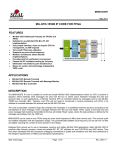
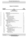
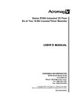
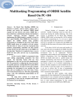
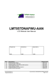
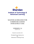
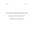
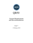
ISSN: 2319-5967 ISO 9001:2008 Certified International Journal of Engineering Science and Innovative Technology (IJESIT) Volume 2, Issue 1, January 2013 Development of Monitoring Unit for Data Acquisition from Avionic Bus 1 Anjana, 2 Dr. N. Satyanarayan, 3M.Vedachary Abstract— 1553 bus is a military avionic bus that describes the mechanical, electrical and functional characteristics of the serial data bus. It is a well proven bus for communication in avionics for 20 years. During the initial stages of hardware and software development, it is important to capture the data flowing on the bus in order to aid offline analysis and diagnosis. To achieve this aim, hardware and software is developed to capture the data through the 1553 bus from the monitor terminal via Ethernet in real time. The project requires the design and development of a monitoring unit interfaced to a host PC which is Windows based via Ethernet. The tool used for both hardware and software development are Embedded Development kit(EDK) and Integrated Software Environment(ISE).EDK is used to design hardware by selecting and connecting peripherals, buses and processor for the custom FPGA board. Xilinx VIRTEX 5 FPGA using PowerPC is implemented for the design. Since 1553 IP core is not a part of the custom board, it is integrated into the FPGA using ISE. The integration process requires the development of the core's user logic, written in VHDL, in order to ensure the compatibility in terms of address, control and data signals. This completes the creation the hardware platform. The hardware platform is now implemented by writing the codes for transfer of data from 1553 to the host PC via Ethernet. In the final stage, both hardware and software is converted to bit streams and downloaded to FPGA for configuration. In the host PC side, a network packet analyzer called Win shark is used to display the data captured from the 1553 bus. Index Terms— EDK, ISE, 1553, User Logic, VIRTEX 5 FPGA. I. INTRODUCTION MIL 1553 is an avionic bus that is used in aerospace vehicles. It was originally designed for use with military avionics, but has also become commonly used in spacecraft on-board data handling (OBDH) subsystems, both military and civil. The design and development of the monitoring unit is to achieve the objectives with high reliability, high speed and low power consumption. The objectives are to capture the data in real time and to use the data for offline analysis and diagnosis. A. HARDWARE COMPONENTS The hardware components used in the design are:1) 1553 IP CORE integrated to FPGA 2) VIRTEX 5 FPGA using POWER PC 3) 1553 Transceiver 4) Transformer 5) Coupler 6) RS232 transceiver 7) HOST PC 8) Ethernet and RS232 cables 9) SRAM, 10) FLASH 11) PROM 12) Power Supply 13) clock 14) JTAG platform cable B. SOFTAWRE COMPONENTS The software tools used are: 1. EDK for embedded system design 2. ISE for analysis and synthesis of HDL 3. HDL and C language 4. WINSHARK which is a network packet analyzer C. BUS COMPONENTS 1553 bus is the main component in our design. It has 3 main components: 1) Bus Controller The bus controller is the central component. It controls the transmission between the remote terminals. The control is based on the command from BC to RT. 2) Remote terminal It is designed to interface various subsystems within the bus. A RT can either be a Bus Controller or a Monitor terminal. Up to 32 terminals can be connected. Each RT has 32 sub addresses. 3) Monitor Terminal 1) Listens to all messages on the bus and records selected activities. Even used in offline mode to observe state and operational mode of the system and subsystems. Mainly used for instrumentation and testing. Provides backup bus controller sufficient information to take over as Bus Controller. 451 ISSN: 2319-5967 ISO 9001:2008 Certified International Journal of Engineering Science and Innovative Technology (IJESIT) Volume 2, Issue 1, January 2013 D. CHARACTERISTICS OF 1553 BUS 1) Data Rate = 1 M bits/sec 2) Word Length = 20 bits 3) Data Bits / Word = 16 bits 4) Message Length = Maximum of 32 data words a. Transmission words 5) technique = Half-duplex 6) Operation = Asynchronous 7) Encoding = Manchester II bi-phase a. Protocol phase 8) = Command/response 9) Bus Control = Single or Multiple 10) Fault Tolerance = Dual Redundant 11) Number of RTs = Maximum of 32 12) Terminal Type = RT, BC and MT a. Controller, Bus Monitor. 13) Transmission Media = twisted shielded pair 14) Coupling = Transformer E. MESSAGE SEQUENCE FROM BC TO RT:Receive command from BC to RT a) BC sends data word to RT. b) RT returns Status word c) Next command word F. MESSAGE FORMAT a) Command Word- All messages start with a command word. Table 1.COMMAND WORD RT address Specifies 32 RTs. Transmit/Receive bit 1-transmit, 0=receive Sub address Specifies 32 sub terminals Word Count No of words to be transferred. . b) Data Word-Data flows from BC to RT. It is a 20 bit data . 3 bit for sync Table 2.DATA WORD 16 bit payload 1 bit for odd parity c) Status Word- RT returns a status word when it receives a data or a command word. Table 3.STATUS WORD RT address Specifies 32 RTs. Message Error Indicates communication error Service request bit Urgent message is given priority Broadcast received Indicates broadcast received of the previous message Busy Bit Indicated when RT does not respond II. HARDWARE AND SOFTWARE TOOLS An Embedded Processor System is developed and implemented in custom board with Virtex 5 Fpga using tools EDK and ISE. A. EMBEDDED DEVELOPMENT KIT (EDK) Embedded development kit is a suite of tools and Intellectual Property that enables you to design a complete embedded processor system for implementation in a Xilinx FPGA. In EDK, the tool called Xilinx Platform Studio (XPS). XPS is a graphical user interface for developing and designing both hardware and software for the embedded design. It also has a graphical editor, which allows 452 ISSN: 2319-5967 ISO 9001:2008 Certified International Journal of Engineering Science and Innovative Technology (IJESIT) Volume 2, Issue 1, January 2013 interconnection of the selected processor, peripherals and buses. In XPS, a wizard called Base System Wizard (BSB) is utilized. Base System Wizard is a tool where we can quickly create a hardware platform by selecting peripherals, buses and processor and interconnecting them. This is the starting point after which one or more IP cores can be imported into XPS. In our project, the peripheral to be imported is 1553 IP core. The processor selected in Virtex 5 FPGA which is 32 bit PowerPC which comes with an interrupt and JTAG controller. The bus 128 bit data wide Processor Local Bus. The peripherals that are selected are UART, Ethernet lite MAC, memory controllers for SRAM and Flash and XPS Timer. BSB also lets you create one or more software application projects. Each software project contains a sample application and a linker script that can be compiled and run on the custom board. B. INTEGRATED SOFTWARE ENVIRONMENT (ISE) ISE is a software tool used for synthesis and analysis of HDL designs. A developer can also perform timing analysis, view RTL diagrams, simulate the design, create bit file and download into FPGA to configure the target device. C. ‘C’ and VHDL C is a software language which is the most widely used language for embedded systems. VHDL is a hardware language that is used to model a design entry. D. WIN SHARK Win shark is a network packet analyzer that captures data in real time and displays data in human readable form. III. HARDWARE DESIGN A. Block Diagram. Fig 1.BLOCK DIAGRAM 1. Xilinx Virtex 5 FPGA FPGA is a programmable array of logic cells that can be made to perform a given function by configuration bit streams. Xilinx VIRTEX 5 FPGA has the following features: 32Kbit dual port RAM. Local BRAMs can store 5,328KB. Array: 160x38( row x col ) Each CLB has 2 slices. Each slice has 4 function generators ( 6 i/p LUT), four FFs, Arithmetic logic gates, large mux and fast carry look ahead chain. 453 ISSN: 2319-5967 ISO 9001:2008 Certified International Journal of Engineering Science and Innovative Technology (IJESIT) Volume 2, Issue 1, January 2013 6 clock management tiles (CMT). Each CMT consists of 2 DCMs (digital clock manager) and 1 PLL. POWER PC:-1 No, 32 bit, 128 bit PLB, 400 MHz clock frequency ETHERNET MAC BLOCKS:-4 No's Maximum user I/O pin:-640 pins Total I/O banks(group of pins):-19 The hardware components selected and connected in the FPGA are:(i) UART UART performs a read/write serial to parallel conversion at processor side and parallel to serial conversion at peripheral side. UART in our design is used for printing the print statements of the code on the hyper terminal. RS232 transceiver is used to convert TTL logic to RS232 logic before sending it to the RS232 cable. (ii) Ethernet-lite MAC The Ethernet Lite MAC supports the IEEE Std. 802.3 Media Independent Interface (MII) to industry standard Physical Layer (PHY) devices and communicates to a processor via a Processor Local Bus (PLB) interface. The design provides a 100 Mbps (also known as Fast Ethernet) Interface. The goal is to provide the minimal functions necessary to provide an Ethernet interface with the least resources used. (iii) RS 232 Transceiver RS 232 transceiver is used to convert TTL logic to RS 232 logic in the RS 232 cable side to ensure compatibility during data transfer. (iv) Mil1553 IP Core (BRM 1553D) The BRM 1553D IP core for FPGA provides a simple to use link for BC, MT or RT that needs to interface with 1553 bus. This IP core supports all three modes. Fig 2.1553 IP CORE 1) The host interface consists of registers and a dual port memory (RAM). 2) RAM size is selectable from 2Kx16 to 64Kx16 in powers of two. 3) CPU controls the core by programming memory and registers. 4) The backend logic arranges messages in a predefined memory and registers structure, which makes interface between the 1553 bus and the local CPU simpler. 5) State machines are responsible for transmission of frames. 6) Encoders/Decoders act as an interface between 16 bit parallel bus and mux serial bus. In our project, four mil1553 IP cores are integrated. In order to integrate the core, ISE is used. The integration of the 1553 IP core and the design of the embedded system follow the FPGA design flow with the help of tool ISE and EDK. FPGA Design Flow 1) Design Entry Source is either created or added in ISE in which VHDL code is written. In our case the user logic or the glue logic for MIL1553 is written in VHDL. Glue logic:-It is an interface logic written in order to ensure compatibility between processor local bus and 1553 core in terms of address, data and control signals. 454 ISSN: 2319-5967 ISO 9001:2008 Certified International Journal of Engineering Science and Innovative Technology (IJESIT) Volume 2, Issue 1, January 2013 2) Design Synthesis Once design is created, the synthesis process will check code syntax and analyze the hierarchy of the design and ensure that the design is optimized for the architecture that is selected. It is a process in which VHDL is translated into net list format resulting in Native Generic Circuit (NGC) file. On completion of design entry of MIL1553 in by writing user logic and synthesizing the user-logic for peripheral mil1553 in ISE, this peripheral is imported to the hardware platform in EDK. The imported peripheral is indicated by a star. Fig 3.Process Synthesis Completed Fig 4. Successful Import Indicated By a Star 3) Design Implementation In design implementation, user constraint file is generated, in which the pin assignments of the peripherals to that of the FPGA is written manually. Implementation process follows Translate, Mapping and Place and Route. Translate combines the net lists and UCF in a file called Native Generic Database (NGD).Mapping divides the complete circuit into logic blocks that can fit into FPGA CLBs. This is represented in a file called Native Circuit Description (NCD) file. Place and Route places logic blocks from mapping process into FPGA configuration logic blocks according to the UCF constraints and connects them. This is represented in a file called as the routed NCD file. 4) Xilinx Device Programming Once the hardware and the software design is completed they are converted into bit streams. The hardware bit streams are system.bit file. The hardware and software combined bit stream is in download.bit file. Bit streams are downloaded into FPGA by XPS through JTAG Platform Cable into the JTAG port of the FPGA for its configuration. File used by XPS to download he bit stream is etc/download.cmd. Since the application codes are large enough to fit into the local BRAMs, a software debug tool called as Xilinx Microprocessor Debugger is used to download the software programs into external SRAMs. Downloading bit streams brings processor out of reset and starts execution. DESIGN ENTRY DESIGN SYNTHESIS DESIGN IMPLEMENTATION XILINX DEVICE PROGRAMMING Fig 5.Xilinx Microprocessor Debugger Xilinx Fig 6.FPGA Design Flow Microprocessor Debugger 455 ISSN: 2319-5967 ISO 9001:2008 Certified International Journal of Engineering Science and Innovative Technology (IJESIT) Volume 2, Issue 1, January 2013 2. 1553 transceiver It is used to convert CMOS/TTL Manchester bi phase signal at the core side into differential signals supported by transformer and vice-versa. 3. Transformer This prevents noise and impedance mismatching. 4. Coupler All Remote Terminals are connected to the 1553 bus via coupler, It mainly prevents signal reflections. 5. Power Supply Power supply required is 5V. 6. Clock System clock is 50MHz.Processor frequency is set to 400MHz and Processor Local Bus frequency to 100MHz. Ethernet transceiver requires 25 MHz frequency. 7. PROM SRAMs are volatile. They lose data when power goes off and FPGA is configured manually every time the power is turned on. With the help of a tool called IMPACT, the bit streams are downloaded into PROM. PROMs do not lose data. When the power is on, the data in the PROM gets automatically downloaded into FPGA. 8. SRAMS. SRAMs are used to execute the software application codes since the local BRAMs present in FPGA are not enough to store the entire application codes. IV. SOFTWARE DESIGN Software application projects are created in Xilinx Platform Studio in EDK. 1. Code to transfer data from 1553 to Ethernet The first application code created under the software application project is to create an Ethernet socket to facilitate data from the board (implemented as the monitor terminal) to the host PC. A network interface is created to add to the Ethernet core. Network interface is created by giving the MAC or the physical address, the address family, the data type and the type of protocol used by the endpoints (both local and remote).In our case, the address family is IPv4, data type is datagram and protocol is User Datagram Protocol (UDP).When Ethernet socket is created, the IP address and port no are automatically generated. IP address is the unique 32 bit address of the machine which uses IP as its protocol and Port No is a 16 bit no used by the kernel to match the incoming data to a particular process. MAC address is a 48 bit address assigned to the network interface or card at the time of manufacture. 2. Code to configure 1553 cores and transfer data from board to host PC via Ethernet The second application code is created to configure the 1553 terminals. Out of four, second is initialized as Remote Terminal (RT), third is initialized as Monitor terminal (MT), fourth is initialized as Bus Controller (BC) and first is left open. The 1553 terminals are configured by programming the required registers and memory. BC is configured to transmit data to the RT.MT is configured to capture the data sent from BC to RT. The registers are programmed to enable enhanced modes, automatic retries, selection of the bus channel, determining stack size etc. Stacks, stack pointers, message counters and message blocks are placed in the fixed area of the shared RAM. These locations are used to read and write data from the data stacks, determine the number of messages sent etc. BC Memory Map CPU selects between channel A and channel B with the help of the 13th bit of configuration register 1.The number of messages to be sent is programmable by means of fixed Message Count Location in Shared RAM. Another fixed location in the shared RAM is for the Stack Pointer. The stack pointer contains a pointer to the Four Word Message Block Descriptor in the Stack Area of the shared ram. Default memory for stack is 256 words (64 messages).BC may be programmed to transmit frames up to 512 unique messages (i.e., 2048 words).Each message is 4 words. The four word message descriptors are:a) Block Status Word Indicates whether message is in progress or complete, the bus channel used for transmission, and detecting errors. b) Time Tag Word It reflects the contents of Time Tag Register which is a 16 bit counter. . For every message processed, value of time tag register is loaded into time tag word during SOM and EOM. Time tag register rolls from FFFF to 0000 for every 65,536 counts. c) Message Gap Time Word 456 ISSN: 2319-5967 ISO 9001:2008 Certified International Journal of Engineering Science and Innovative Technology (IJESIT) Volume 2, Issue 1, January 2013 It contains BC message time which is time from start of a message to the start of the next message. It can be from 1us to 65535us. d) Message Block Pointer Message Block Pointer points to the message blocks. e) Message Blocks The capacity of the message block is 38 words. The first word is the control word, then the command word, then the data words (up to 32 words) and finally status words MT Memory Map 1553 messages are selectively monitored based on RT address, T/R, and Sub address .All messages on 1553 bus are stored in shared RAM. The message monitor contains two stacks: a command stack and a data stack. The pointers to these stacks are in a fixed location in the RAM. When a valid command is received, the terminal will point to the selective monitor lookup table (a fixed block of RAM) to determine if this command is enabled. The address for this location that is the LOOK UP TABLE is determined by RT address, T/R, and Sub address bit 4 of the current command word and adding it to base address 0280(hex). The bit location within this 16 bit is determined by sub address 3…0 of the current command word. If the bit in the lookup table is „0‟ then the command is not enabled and the terminal will stop processing of this message. If it is „1‟, the command is enabled and the terminal will create an entry in the monitor command stack (based on monitor command stack pointer) and store the data associated with this command into sequential data locations in the monitor data stack. Fig 7.BC MEMORY MAP Fig 8.MT MEMORY MAP 3. Application code to receive data in the host PC side This application code is created in the host PC side. An Ethernet socket is created in the host PC side in order to receive data captured by monitor terminal. The host PC receives the data and stores the data in files created in the application code. Fig 9.Data seen in HyperTerminal 457 ISSN: 2319-5967 ISO 9001:2008 Certified International Journal of Engineering Science and Innovative Technology (IJESIT) Volume 2, Issue 1, January 2013 V. OUTPUTS Fig 10.Output in file format Fig 11.Output in Win shark VI. APPLICATION a) Navigation b) Instrumentation c) Testing d) Offline analysis and diagnosis of data. VII. FLOW OF OPERATION Upon the execution of the application codes by PowerPC, the IP core configured as Bus Controller sends data to the IP core configured as Remote Terminal through 1553 bus. First it sends a command word which gives the RT address, whether receive or transmit, RT sub address and the number of words transmitted. Then, BC sends data words to RT. After receiving the complete data words, the corresponding RT returns with a Status word. The IP core configured as Monitor Terminal listens to the messages and captures the data from the bus in real time and transmits it to the host PC via Ethernet. The host PC receives the data and stores in the file created in the application code. The data can also be captured by a Win Shark which is a network packet analyzer. UART prints the “print statements” of the code which includes the data sent from Bus Controller to the Remote terminal on the hyper terminal. VIII. CONCLUSION In this paper, hardware and software is designed for a monitoring unit that is required to capture data from the 1553 bus in real time. Tools like EDK and ISE is used to aid the hardware and software design.EDK helps create hardware platform which is implemented by writing application codes. Since 1553 IP core is not a custom peripheral for VIRTEX 5 FPGAs, its glue logic is developed with the help of ISE, to facilitate its integration in FPGA, enabling compatibility between processor and the IP core. Software application codes are developed in EDK to configure the 1553 terminals and to facilitate data capture by monitor terminal interfaced to host PC through Ethernet. Hardware and software design together is converted to bit stream and downloaded into FPGA, for its configuration. When the application codes are made to run, the data transferred from BC to RT, captured by MT is displayed in the host PC or Win shark. IX. ABBREVIATIONS AND ACRONYMS FPGA-Field Programmable Gate Array UART-Universal Asynchronous Receiver Transceiver EDK-Embedded Development Kit ISE-Integrated Software Environment UCF-User Constraint File IP- Intellectual Property 458 ISSN: 2319-5967 ISO 9001:2008 Certified International Journal of Engineering Science and Innovative Technology (IJESIT) Volume 2, Issue 1, January 2013 XPS-Xilinx Platform Studio BSB-Base System Builder ACKNOWLEDGMENT I thank the scientists of DRDO, Hyderabad, Mr. J.V Satyanarayana (scientist E) who is my project guide, Mr. Anil Meena (scientist C) and Mr. Ramakrishna for their unconditional support. I also thank my co-authors Dr. N. Satyanarayan (Professor and Director, CMRCET) who is also my project guide and M.Vedachary (Associate Professor and Project Coordinator) in helping me write this paper. REFERENCES [1] DDC‟s ACE/Mini ACE Series BC/RT/MT Advanced Communication Engine Integrated 1553 Terminal. [2] SITAL Technology‟s BRM1553D user manual. [3] EDK OS and Libraries Reference Guide. [4] Xilinx documentations. . 459