1
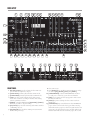
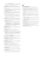
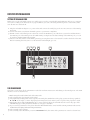
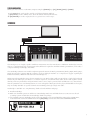
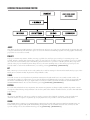
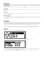
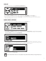
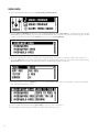
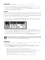
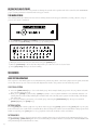
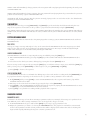
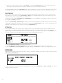
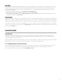
1 IMPORTANT SAFETY INSTRUCTIONS Carefully read these instructions, follow them and save them for future reference. 1. Do not use the unit near water. 2. Never use any aggressive cleaners on the casing or the LCD screen. Remove dust, dirt and fingerprints with a soft dry cloth. More persistent dirt can be removed with a slightly damp cloth using only water. Disconnect all connectors while doing this. Do not reconnect them until the product is safely dry. 3. To avoid scratches or damage, never use sharp objects near the display. Also avoid applying any pressure to the display itself. 4. Install in accordance with the manufacturer’s instructions. Make sure you place the unit on a stable surface before use. If you mount the unit in a rack, be sure to tighten all four screws in the rack mount holes. 5. When transporting the unit, use accessories recommended by the manufacturer or the box and padding the unit was originally shipped in. 6. Do not install near any heat sources such as radiators, heat registers, stoves, or any other source (including amplifiers) producing heat. 7. In the EU, only use CE approved power cords. 8. Do not block the ventilation holes located on the side and the bottom of the enclosure of the unit. 9. Do not put the PL-2 Protective Cover (Analog Four accessory) on the unit while the unit is powered on. 10.This product, either alone or in combination with an amplifier and headphones or speakers, may be capable of producing sound levels that could cause permanent hearing loss. Do not operate for a long period of time at a high volume level or at a level that is uncomfortable. 11. Protect the power cord from being walked on or pinched particularly at plugs, convenience receptacles, and the point where they exit from the unit. 12.Only use attachments/accessories specified by the manufacturer. 13.Unplug the unit during lightning storms or when unused for long periods of time. 14.Leave all servicing to qualified service technicians. Servicing is required when the unit has been damaged in any way, such as power supply cord or plug damage, liquid having been spilled or objects have fallen into the unit, if the unit has been exposed to rain or moisture, does not operate normally, or has been dropped. WARNING To reduce the risk of fire, electrical shock or product damage: •Do not expose the unit to rain, moisture, dripping or splashing and also avoid placing objects filled with liquid, such as vases, on the unit. •Do not expose the unit to direct sunlight, nor use it in ambient temperatures exceeding 35°C. •Only use accessories recommended by the manufacturer. •Do not open the casing. There are no user repairable or adjustable parts inside. Leave service and repairs to trained service technicians only. ADDITIONAL INSTRUCTIONS FOR THE POWER ADAPTER ELEKTRON PSU-3 WARNING •The adapter is not safety grounded and may only be used indoors. •To ensure good ventilation for the adapter, do not place it in tight spaces. To prevent risk of electric shock and fire because of overheating, ensure that curtains and other objects do not prevent adapter ventilation. •Do not expose the power adapter to direct sunlight, nor use it in ambient temperatures exceeding 40°C. •Connect the adapter to an easily accessible electrical outlet close to the unit. •The adapter is in standby mode when the power cord is connected, the primary circuit is always active as long as the cord is connected to the power outlet. Pull out the power cord to completely disconnect the adapter. Elektron machines are sold with a three year EU warranty, starting from the date of the original purchase. Being able to prove the date of the original purchase with an invoice or a receipt is necessary if you require warranty service. If the machine should need a repair during the warranty period no charges will be applied for parts or labor. This warranty is transferable to other owners should the Elektron machine be resold during the warranty period. Items belonging to the Elektron Style range of products (t-shirts, stickers, posters etc.) are not covered by this warranty. This warranty does not cover (a) damage, deterioration or malfunction resulting from accident, negligence, misuse, abuse, improper installation or operation or failure to follow instructions according to either the Getting Started Manual or the full reference manual for this product; any shipment of the product (claims must be presented to the carrier); repair or attempted repair by anyone other than Elektron or a certified Elektron repair center (b) any unit which has been altered or on which the serial number has been defaced, modified or removed; (c) normal wear and any periodic maintenance; (d) deterioration due to perspiration, corrosive atmosphere or other external causes such as extremes in temperature or humidity; (e) damages attributable to power line surge or related electrical abnormalities, lightning damage or acts of God; or (f) RFI/EMI (interference/noise) caused by improper grounding or the improper use of either certified or uncertified equipment, if applicable. Warranty service procedure for machines bought from a retailer Please contact their support if you need warranty service. You will then be guided how to proceed with your errand. Note that the Elektron three year limited warranty is in addition to any warranty your retailer may offer. Warranty service procedure for machines bought from the Elektron Online Shop Contact the Elektron Support at www.elektron.se if you need warranty service. You cannot send a unit to a certified Elektron repair center unless agreed to by Elektron. The customer is responsible for shipping charges if the machine needs to be shipped to a certified Elektron repair center for warranty service. Elektron covers the shipping back to the customer during the warranty period. Should the unit be dead on arrival, or if the hardware malfunctions within 2 weeks of the original purchase date, Elektron will cover the shipping to a certified Elektron repair center. 2 THANK YOU Thank you for purchasing the Analog Four. This Getting Started guide covers the basics of the machine. The complete User Manual is available as a digital download at www.elektron.se. We wish you a happy analog experience! —The Elektron Team 3 PANEL LAYOUT 2 3 4 5 6 7 8 9 10 11 12 13 14 15 16 1 34 33 17 32 18 19 20 31 30 1 FRONT PANEL 29 28 2 27 26 25 3 24 23 4 1 MASTER VOLUME sets the volume for the main outputs and the headphones output. 2 [SONG MODE] activates/deactivates SONG mode. 3 [CHAIN MODE] activates/deactivates CHAIN mode. 4 LEVEL sets the overall volume level of the active track. Also used for scrolling in menus and setting various parameter values. 5 [TEMPO] opens the TEMPO menu. [FUNCTION] + [TEMPO] makes it possible to tap the tempo. 6 [YES/SAVE] key. Used for entering sub-menus and for confirming choices. 7 [NO/RELOAD] key. Used for exiting an active menu and backing one step. 4 22 5 21 6 7 8 9 10 11 8 The LCD screen. 9 The [ARROW] keys. Used for menu navigation. They are called [UP], [DOWN], [LEFT] and [RIGHT]. 10 [PERFORMANCE] activate PERFORMANCE mode. A second press on the key opens the track mixer. 11 [ARP] key. Controls for the arpeggiator of the active track are found here. 12 [NOTE] key. Note settings for the active track are made here. 13 [PARAMETER] keys switch between the PARAMETER pages of the active track. The upper white text legend indicates the pages for the four synth tracks. The gray text is for the FX track pages and the white text line beneath indicates the CV track pages. A second press on the [PARAMETER] key will open secondary PARAMETER pages. <PARAMETER> LED indicates if the first (red) or second (green) page is active. 14 DATA ENTRY knobs. Used for adjusting parameters. 15 <TRACK> LEDs indicating the active track and muted tracks. 16 The [TRACK] keys selects the active track. Four synth tracks, one FX track and one CV track are available. [FUNCTION] + [TRACK] mutes a track. 17 [TRANSPOSE] transposes the octave for the mini-keyboard and the note trigs on a sequencer pattern. 18 The <TRANSPOSE> LED indicates if the transpose lock functionality is activated or not. 19 <PATTERN PAGE> LEDs indicate how many pattern pages the active pattern consists of and which pattern page is currently active. The LED flashes on the pattern page currently playing. 20 [PAGE] selects the active pattern page in GRID RECORDING mode. The active pattern page is shown on the four LEDs above the key. The secondary function accesses the SCALE menu. 21 [KEYBOARD] keys are used for playing sounds and assigning note values to note trigs. The first key is called [KEYBOARD C1]. The secondary functions of the [KEYBOARD C1] through to [KEYBOARD C2] keys are the KIT, SOUND, TRACK, PATTERN, SONG, CLICK, SWING and GLOBAL menus, respectively. 22 <OCTAVE> LEDs shows the octave transposition for the [KEYBOARD] keys. 23 [STOP] stops playback. The secondary function is a paste operation. 24 [PLAY] starts the playback of the sequencer. The secondary function is a clear operation. 25 [RECORD] key. activates/deactivates GRID RECORDING mode. Starts LIVE RECORDING if held while pressing [PLAY]. If held while double-pressing [PLAY], QUANTIZATION is activated/deactivated. The secondary function is a copy operation. 26 <BANK GROUP> LED indicates if bank group A-D or E-H is accessed by the [BANK] keys. 27 [BANK D/H] selects bank D or H. The secondary function opens the PARAMETER SLIDE menu. 28 [BANK C/G] selects bank C or G. The secondary function opens the NOTE SLIDE menu. 29 [BANK B/F] selects bank B or F. The secondary function opens the ACCENT menu. 30 [BANK A/E] selects bank A or E. The secondary function opens the TRIG MUTE menu. 31 [TRIG] keys are used for entering trigs to the sequencer. Also used for selecting patterns. 32 <PATTERN MODE> LED indicates the selected PATTERN mode: sequential (off), direct start (red) or direct jump (green). 33 [BANK GROUP] key. Selects the active bank group (A-D or E-H). The secondary function activates different PATTERN modes. 34 [FUNCTION] key. Press and hold for accessing secondary functions for some of the other keys. Secondary functions are generally written in red text on the panel. REAR 1 Power on/off switch. 2 12V DC power in. Use the included Elektron PSU-3 power adapter, connected to a power outlet. 3 Full Speed USB 2.0 connection. Use the included A to B USB 2.0 connector cable to a computer host. 4 MIDI Thru. Use standard MIDI cable to connect another MIDI unit in chain. Duplicates MIDI In data stream. 5 MIDI Out. Use standard MIDI cable to connect to MIDI In of an external MIDI unit in order to control it. 6 MIDI In. Use standard MIDI cable to connect MIDI Out of an external MIDI unit to control the Analog Four. 7 CV outputs C and D. Connect to external synth with CV inputs. Use either standard 1/4” mono phone plug or 1/4” insert/Y cable. 8 CV outputs A and B. Same recommended connectors as above. 9 Audio Input L/R. Use standard 1/4” mono phone plug to input sound from other synthesizers or mixers. 10 Audio Output L/R. Use either 1/4” mono phone plug (unbalanced connection) or 1/4” Tip/Ring/Sleeve phone plug (balanced connection). 11 Headphones Output. Connect standard headphones with 1/4” stereo phone plug. 5 FIRST STEPS WITH THE ANALOG FOUR SETTING UP THE ANALOG FOUR Make sure you place the Analog Four on a stable support, such as a sturdy table with sufficient cable space, or mount in a rack according to the instructions on page 16. Before you start connecting the Analog Four to other units, make sure all units are switched off. 1 Plug the included DC adapter to a power outlet and connect the small plug to the 12 V DC connector of the Analog Four unit. 2 Connect the main out L/R from the Analog Four to your mixer or amplifier. 3 If MIDI control of the Analog Four is desired, connect the MIDI OUT port of the device you wish send data from to the MIDI IN port of the Analog Four. The MIDI THRU port duplicates the data arriving at the MIDI IN port, so it can be used for chaining MIDI units together. 4 Switch on all units. Switch on the Analog Four by pressing the Power rocker switch located at the back of the unit. Before restarting the unit, wait 2 seconds after the LCD backlight goes out. 1 2 3 4 5 7 6 THE USER INTERFACE The LCD screen shows all the information needed for real-time interaction and editing on the Analog Four. The main interface screen is shown below: 1 Bar showing the overall volume level of the active track. 2 The current tempo shown with one decimal. 3 The playback/recording status of the sequencer shown by the standard »record«, »play«, »pause« and »stop« symbols: . To the right a counter displaying how many bars, beats and steps the sequencer has played is located. 4 Information about which PARAMETER page is active. The line above the text indicates the active sub page of the PARAMETER page. A fully drawn line means no sub page is available. 5 Up to ten track parameters. They show what the DATA ENTRY knobs control and the current parameter values. Press and turn a knob to adjust parameters in larger increments. 6 The currently active pattern. 7 The currently active kit. When you turn a DATA ENTRY knob, the name of the parameter it controls is shown here. 6 SCREEN NAVIGATION When you enter a menu or sub-menu, navigate using the [ARROW] keys [UP], [DOWN], [LEFT] or [RIGHT]. 8 The LEVEL knob can be used to quickly scroll through menus and lists. 9 [YES/SAVE] is used to affirm, select, enter sub-menus and tick/untick boxes. 10 [NO/RELOAD] is used to negate, deselect or go back one or more steps. OVERBRIDGE The Analog Four is a highly capable standalone instrument. Since the introduction of Elektron Overbridge, however, there is a complementary way of interacting with it. All that is required is an Elektron Analog instrument, a USB cable, a computer running Overbridge, and a DAW. The Overbridge software suite enables a tight integration between the Analog instruments (Analog Rytm, Analog Keys, Analog Four) and a computer DAW. If you want to hook up multiple machines to a computer, we suggest acquiring the Elektron Overhub, a Multi-TT hub tailored for Overbridge use. When using the Overbridge setup, the user interface for your Analog device will present itself as a clearly laid out plugin window in your DAW. Sync your device to a software sequencer, record multi track audio, browse and organize sounds, edit kits, and set up modulation and performance macros via a simple point-and-click workflow. Access, edit and automate all parameters for sound manipulation on screen. Though the Analog Four lacks physical individual track outputs, they are readily available as separate channels via Overbridge, through a single USB cable. Overbridge is available as a complimentary download on the Elektron webpage. 1 Install Overbridge. 2 Make sure the Analog Four OS and the OS of Overbridge match. You will find the most recent versions of both operating systems included in the Overbridge download package. 3 Set your Analog Four to Overbridge mode on the USB CONFIG screen. You will find this setting in the SYSTEM menu, located at the far south of the GLOBAL menu. Press [YES/SAVE] to tick the box and activate OVERBRIDGE MODE. 7 EXPERIMENTING WITH PATTERNS The Analog Four is equipped with several preset patterns, kits and Sounds. To immediately start experimenting with the Analog Four, just follow the instructions below. 1 Switch on the Analog Four. 2 Press [PLAY] to listen to pattern A01. 3 Select pattern A02, which is the second demo pattern, by first making sure bank group A-D is selected. The <BANK GROUP> indicates the selected bank group. If A-D is not selected, press the [BANK GROUP] key. 4 Pressing [BANK A/E] + [TRIG] key 2 will make pattern A02 play once the currently playing pattern finishes. Pattern A03 is selected by pressing [BANK A/E] + [TRIG] key 3 and so on. 5 Mute tracks by pressing [FUNCTION] + the [TRACK] key of the track you want to mute. Unmute by repeating the procedure. 6 Press [STOP] to stop playback. PERFORMANCE MODE The PERFORMANCE mode makes it possible for the DATA ENTRY knobs to control several PARAMETER page parameters at once. These parameter mappings are called a parameter macro. 1 Make sure a pattern is playing. 2 Press the [PERFORMANCE] key to access PERFORMANCE mode. 3 Turn the DATA ENTRY knobs and listen how the sound of pattern changes. ADJUSTING PARAMETERS Each track contains six PARAMETER pages. There parameters affecting the sound of the track are found. 1 Make sure a pattern is playing. 2 Press the [TRACK] key of one of the four synth tracks. 3 To change the cutoff of the ladder filter, press the [FILTERS] key. The FILTERS page will open. The parameter labelled FRQ changes the cutoff of the ladder filter. Turn DATA ENTRY knob A to change the parameter value. 4 Try out the rest of the PARAMETER page parameters to experiment with the sound shaping possibilities. 5 To reload the Sound to its original state, press [NO/RELOAD] + [KEYBOARD D1]. 6 To reload the whole kit to its original state, press [NO/RELOAD] + [KEYBOARD C1]. 8 OVERVIEW OF THE ANALOG FOUR DATA STRUCTURE +DRIVE SOUND LIBRARY 4096 SOUNDS 4 SOUNDS CV FX +DRIVE The +Drive is the non-volatile memory of the Analog Four. It keeps up to 128 projects (thousands of patterns, kits and songs) stored internally. The +Drive also gives access to the +Drive Sound library, capable of storing 4096 Sounds. Every project has access to these Sounds. PROJECT A project contains 128 patterns, 128 kits, 16 songs, 4 global slots, and a project Sound pool consisting of up to 128 Sounds. Generic settings and states (tempo, mutes et cetera) are also stored in each project. When a project is loaded it becomes the active working state of the Analog Four. From here it is possible to edit the patterns, kits, songs and globals of the project. The Analog Four always boots to the active working state, i.e. the active project. Projects are saved, loaded et cetera in the GLOBAL menu, accessed by pressing [FUNCTION] + [KEYBOARD C2]. KIT Kits contain up to four Sounds, one for each synth track, as well as settings for the FX and CV tracks. Each project of the Analog Four contains 128 kits. A pattern is always linked to a kit. SOUND A Sound consists of stored synth track parameter settings. Each synth track hosts one Sound. Sounds can also be stored in the Sound pool of the active project or in the +Drive Sound library. The Sound pool can host 128 Sounds and the +Drive Sound library holds up to 4096 sounds. Sounds are loaded to the kit from either the SOUND BROWSER or SOUND MANAGER menus. Access these menus by pressing [FUNCTION] + [KEYBOARD D1]. PATTERN For each of the 8 banks there are 16 patterns. This means 128 patterns are always readily available. A pattern consists of sequencer data like trigs and parameter locks for the synth tracks and the FX and CV tracks, as well as ARP and NOTE page settings. SONG 16 songs are available for each project. They are used to sequence the playback of patterns. Songs are built from chains. A chain is a sequence of patterns. Up to 256 pattern slots are possible to allocate between 64 chains. GLOBAL The GLOBAL menu contains project management, settings for the synth and sequencer, Analog Four MIDI setup, CV functionality, OS upgrade and SysEx data handling. Four global slots are available and each slot can have its own specific settings. Access the GLOBAL menu by pressing [FUNCTION] + [KEYBOARD C2]. 9 ABOUT THE TRACKS THE SYNTH TRACKS The synth tracks consist of track 1-4. To edit one of them, press [TRACK] key 1-4. Sounds are loaded to the synth tracks. THE FX TRACK The FX track controls the Analog Four internal master effects and external audio inputs. To edit the FX track, press the [TRACK] key 5. THE CV TRACK The CV track is used for controlling external equipment capable of receiving analog CV and Gate signals. To edit the CV track, press [TRACK] key 6. EDITING THE TRACKS The six [PARAMETER] keys open pages that are used for editing the tracks. They contain different parameters depending on the track type. Edit parameters using the DATA ENTRY knobs. Press and turn a knob to adjust its parameter in larger increments. KITS AND SOUNDS Kits and Sounds are the basic building blocks of the Analog Four. Kits can be regarded as a collection of Sounds as well as other settings. A Sound is essentially a synth track patch. Sounds can be loaded to any of the synth tracks. A Sound that has been loaded becomes a part of the active kit. Any changes made to a loaded Sound will not affect the loaded Sound, it will affect the active kit. A pattern, controlling the playback of the kit, is always linked to a kit. LOADING A KIT 1 Open the KIT menu by pressing [FUNCTION] + [KEYBOARD C1]. 2 Use the [UP] and [DOWN] arrow keys to select LOAD KIT. Press [YES/SAVE] to open the menu. 3 The LOAD KIT menu contains up to 128 saved kits. The currently active kit is indicated by inverted graphics. Select the kit to be loaded by using the [ARROW] keys or the LEVEL knob. 4 Once a kit has been selected, press [YES/SAVE] to load it. The active pattern will be linked to the loaded kit. 10 SAVING A KIT 1 Open the KIT menu by pressing [FUNCTION] + [KEYBOARD C1]. 2 Use the [UP] and [DOWN] arrow keys to select SAVE KIT. Press [YES/SAVE] to open the menu. 3 Select the position to which the kit should be saved by using the [ARROW] keys or the LEVEL knob. 4 Once a position has been selected, press [YES/SAVE] to save the kit. The naming menu will appear. Read more about the naming menu on page 13. LOADING A SOUND TO A SYNTH TRACK 1 Select the synth track the Sound will be loaded to by pressing [TRACK] key 1-4. 2 Open the SOUND menu by pressing [FUNCTION] + [KEYBOARD D1]. 3 Use the [UP] and [DOWN] arrow keys to select SOUND BROWSER. Press [YES/SAVE] to open the menu. The SOUND BROWSER shows a list of all Sounds residing in either the +Drive Sound library or the Sound pool. Scroll the list by turning the LEVEL knob or by pressing [UP]/[DOWN]. 4 By factory default, the +Drive Sound library is being browsed. If the Sound should be loaded from the Sound pool, press the [LEFT] arrow key. The SORTING menu will open. Highlighting the first option in the menu and pressing [YES/SAVE] switches between browsing the +Drive Sound library and the Sound pool. 5 Load a Sound by pressing [YES/SAVE]. The SOUND BROWSER can be accessed quickly for any synth track by double-pressing [TRACK] key 1-4. 11 SAVING A SOUND 1 Open the SOUND menu by pressing [FUNCTION] + [KEYBOARD D1]. 2 Use the [UP] and [DOWN] arrow keys to select SOUND MANAGER. Press [YES/SAVE] to open the menu. The SOUND MANAGER is a more powerful version of the SOUND BROWSER. Here Sounds can be saved, loaded, tagged, locked et cetera. Scroll the list by turning the LEVEL knob or by pressing [UP]/[DOWN]. 3 By factory default, the +Drive Sound library is being browsed. If you wish to save the Sound to the Sound pool, press the [LEFT] arrow key. The SORTING menu will open. Highlighting the first option in the menu and pressing [YES/SAVE] switches between browsing the +Drive Sound library and the Sound pool. 4 Select an empty slot. Press [RIGHT] to access the SOUND OPERATIONS menu. The available operations will affect the currently highlighted Sound. 5 Select STORE TRACK SOUND. Press [YES/SAVE] to store it to the selected slot. 6 The NAMING menu will appear. Read more about this menu on page 13. 12 PLAYING A SOUND Play a Sound using the [KEYBOARD] or an external MIDI keyboard connected to the Analog Four. 1 Select the Sound you wish to play by pressing one of the [TRACK] keys 1-4. The information bar in the lower left corner of the LCD screen will briefly change to show the name of the loaded Sound. 2 To change octaves, press the [UP] and [DOWN] arrow keys. The first and last [KEYBOARD] keys play a C note. The <OCTAVE> LEDs indicate which octave is selected. 3 Sounds can be played polyphonically. See POLYPHONY below. POLYPHONY The Analog Four is capable of four voice multitimbral polyphony (or unison). This is possible due to the versatile sound engine that can change sound instantly and allow completely dynamic voice allocation. The sequencer is fully polyphonic, allowing overlapping notes and chords to be programmed on the tracks. Any track can play up to four notes using its own track sound. Notes are distributed to the synth voices according to a user-selectable allocation method. Certain synth voices can also be poly-disabled, allowing tracks to have their dedicated, monophonic synth voice available at all times. The poly configuration is stored per kit, for maximum flexibility. 1 Open the KIT menu by pressing [FUNCTION] + [KEYBOARD C1]. Then open the POLY CONFIG menu, found at the bottom of the KIT menu, by highlighting it and pressing [YES/SAVE]. Select the menu options by pressing the [UP]/[DOWN] arrow keys. 2 Select any combination of the four VOICES to be poly enabled by using the [LEFT] and [RIGHT] arrow keys. Tick or untick a box by pressing the [YES/SAVE] key. Voices that are not set to be poly-enabled will be dedicated monophonic voices for their corresponding tracks. These will never be used for polyphonic playback. Voices that are set to be poly-enabled will be allocated dynamically by any of the poly-enabled tracks. 3 ALLOCATION changes the allocation method of the four voices, or sets all four voices to play simultaneously (RESET, ROTATE, REASSIGN or UNISON, respectively). Select mode with the [LEFT] and [RIGHT] arrow keys. In the POLY CONFIG menu, you can activate/deactivate voice 1-4 directly. Just press [TRIG] key 1 through 4. When in the POLY CONFIG menu, the red LEDs above [TRIG] key 1-4 will be half-bright. When a voice is activated, the corresponding LED will light up full-bright. EDITING A SOUND 1 Select one of the synth tracks by pressing [TRACK] keys 1-4. The kit Sound of the active synth track is the one that will be edited. 2 Adjust the overall volume level of the active track with the LEVEL knob. 3 Edit a Sound by adjusting the parameters found on the synth track PARAMETER pages. Access these pages by pressing the [PARAMETER] page keys. If a page contains a subpage, press the [PARAMETER] page key again to access it. Use the DATA ENTRY knobs to change the parameters. OSC1 controls oscillator 1. Contains one sub page for the noise generator. OSC2 controls oscillator 2. The sub page contains parameters relevant for both oscillators. FILTERS controls the two filters and the overdrive. One 24 dB/octave 4-pole lowpass ladder filter and one 2-pole multimode filter are available, connected in series with the overdrive between them. AMP contains parameters for the amplitude envelope. Effect sends are found here as well. ENV offers two freely assignable envelopes. The first one also controls the filters. The second envelope is located in a subpage. LFO is where parameters for the two freely assignable LFOs are found. Contains one subpage. 13 EDITING THE FX AND CV TRACKS Editing the FX and CV tracks is very similar to editing the Sounds of the synth tracks of the active kit. The PARAMETER pages contain parameters relevant for the two types of track. THE NAMING SCREEN The naming method is identical for the various naming situations that appear when kits, Sounds, patterns, songs or projects are saved or renamed. 1 Use [ARROW] keys [LEFT] and [RIGHT] to navigate between the letters. 2 Press and hold [FUNCTION] to access the pop-up naming menu. 3 Navigate between the letters in this menu using the [ARROW] keys. 4 Release [FUNCTION] to insert the letter. Repeat the procedure for each successive letter. 5 Press [YES/SAVE] when you are done naming. THE SEQUENCER BASIC PATTERN OPERATIONS The sequencer of the Analog Four stores information in patterns. A pattern controls the playback of the synth, FX and CV tracks and various aspects of these tracks. All adjustments made to the patterns are automatically saved. SELECTING A PATTERN 1 Press the [BANK GROUP] key to choose the bank group. If for example bank group A-D is chosen, patterns in banks A, B, C and D can be selected. 2 Next, press a [BANK] key followed by a [TRIG] key (1-16) to select a pattern within the selected bank. Patterns containing data are indicated by half-bright red <TRIG> LEDs. The currently active pattern is indicated by a full-bright red <TRIG> LED. 3 To select, for example, pattern B05, select bank group A-D using the [BANK GROUP] key. Then press and hold [BANK B/F] and press [TRIG] key 5. PATTERN CONTROL Pressing [PLAY] will start the playback of a pattern. Pause by pressing [PLAY] again. Pressing [STOP] will stop the playback of all tracks. The sound will be cut off, but effects like the delay will continue to be heard until the delay repeats have faded out. Quickly press [STOP] twice to stop playback of all tracks and fade out the send effects. PATTERN MODES When changing patterns, the new pattern can be started in three ways. Toggle between the PATTERN modes by pressing [FUNCTION] + [BANK GROUP]. The LCD screen will briefly show which mode is activated. The <PATTERN MODE> LED will permanently show which mode is active. 14 DIRECT START will immediately change patterns. The new pattern will start playing from the beginning. Shown by a red <PATTERN MODE> LED. DIRECT JUMP will immediately change patterns. The new pattern will start playing from the position where the previous pattern left off. Shown by a green <PATTERN MODE> LED. SEQUENTIAL will change patterns after the pattern currently playing reaches its end. This mode is the default mode. Shown by an unlit <PATTERN MODE> LED. TRACK MUTING Muting tracks is done by pressing [FUNCTION] + the [TRACK] key of the track that should be muted. Only the note trigs of the sequencer are muted. It is still possible to play a muted track manually using the [KEYBOARD]. The <TRACK> LEDs indicate the mute status. Unlit <TRACK> LED indicate the muted tracks. Green <TRACK> LEDs indicate audible tracks. A red <TRACK> LED indicates the active, audible track. A yellow <TRACK> LED indicates an active, muted track. PATTERN RECORDING MODES The Analog Four offers two main modes of inputting trigs when creating a pattern: GRID RECORDING mode and LIVE RECORDING mode. TRIG TYPES Two types of trigs, note trigs and trigless locks, can be entered in the RECORDING modes. Note trigs trig notes while trigless locks can be used to apply parameter locks without trigging notes. Note trigs are indicated by full-bright <TRIG> LEDs and trigless locks are indicated by half-bright <TRIG> LEDs. GRID RECORDING MODE GRID RECORDING is a method of composing where trigs are added by using the [TRIG] keys. 1 Enter GRID RECORDING mode by pressing the [REC] key. A lit red <REC> LED indicates GRID RECORDING mode is active. 2 Select the track to which you want to add trigs by pressing the relevant [TRACK] button. Place note trigs on the sequencer by pressing the [TRIG] keys. To add note values to trigs, press and hold a [TRIG] key while pressing a key on the [KEYBOARD]. To add a trigless lock, press [FUNCTION] and [TRIG]. 3 Press [PLAY] to listen to the sequence. LIVE RECORDING MODE LIVE RECORDING mode is the second method of adding trigs to the tracks. In this recording mode, the [KEYBOARD] can be played in real time to input trigs to the tracks. It is also possible to enter parameter locks in real time. 1 Hold [RECORD] while pressing [PLAY] to enter LIVE RECORDING mode. The sequencer will start to play and the <RECORD> LED will start to flash. 2 Enter trigs to the active track in real time by pressing the keys on the [KEYBOARD]. 3 Press [PLAY] to exit LIVE RECORDING mode while keeping the sequencer playing. If LIVE RECORDING mode is active and [REC] is pressed, GRID RECORDING mode will be entered. 4 Press [STOP] to stop both the recording and the playback of the sequencer. SEQUENCER FEATURES PARAMETER LOCKS Parameter locks allow trigs to have their own unique parameter values. For example, all note trigs of a synth track can have different pitch or filter settings. Parameter locks can be applied to all types of tracks. 1 In GRID RECORDING mode, press and hold the [TRIG] key of a trig to apply parameter locks. 2 Adjust the parameters you want to lock using the DATA ENTRY knobs. The graphics in LCD will become inverted for the locked parameter and the locked parameter value will be displayed. The <TRIG> LED of the locked trig will begin to flash rapidly, indicating the trig now contains a parameter lock. 15 3 Remove a single parameter lock by holding [TRIG] + pressing the DATA ENTRY knob of the locked parameter. By removing a note trig and entering it again, all parameter locks will be erased from the trig. In LIVE RECORDING mode, turn a DATA ENTRY knob to input parameter locks to the active track. Note trigs will be locked accordingly and trigless locks containing the locks will be placed on the sequencer steps not containing note trigs. TRACK TRANSPOSE Tracks can be transposed in real time. The tracks that will be affected by this functionality are set in the NOTE SETUP menu, which is accessed by pressing [FUNCTION] + [NOTE]. The TRK TRANSPOSABLE setting in this menu needs to be activated for the track to be affected by the transpositions. To transpose, press and hold [TRANSPOSE] + a [KEYBOARD] key. Select a different octave range to transpose to by pressing the [UP] or [DOWN] arrow keys. If you press [FUNCTION] + [TRANSPOSE], the transpose lock functionality will be activated. Transpose lock is shown by a full-bright <TRANSPOSE> LED. When this function is activated, the [TRANSPOSE] key will act as if constantly pressed, enabling one-handed transpositions when pressing the [KEYBOARD] keys. PATTERN SCALE The length and timing of the pattern can be changed on this screen. The leftmost figure shows the number of steps in the pattern. The maximum number of steps is determined by the total length, which is shown on the right. The rightmost figure controls the time signature of the pattern. If 17 steps or more are used in a pattern, the [PAGE] key can be used to toggle between the different pattern pages when in GRID RECORDING mode. 1 Press [FUNCTION] + [PAGE] to access the scale screen. 2 Use the [ARROW] keys [LEFT] and [RIGHT] to toggle between step length/total length or time signature. 3 Use the [ARROW] keys [UP] and [DOWN] to change the settings. The LEVEL knob can be used to change settings as well. PATTERN SWING Adjust the swing setting of the pattern, in order to employ a propulsive, rhythmic groove. Access this screen by pressing [FUNCTION] + [KEYBOARD B1]. Set the SWING ratio to 51-80%, by turning the LEVEL knob or by pressing [ARROW] keys [UP] or [DOWN]. The default setting is equal spacing, 50%. 16 MULTI MAP Multi map allows custom mapped keyboards splits, pattern trigging per key, Sound trig per key, MIDI trig of external synths, and more. With a multi map, full analog drum kits, bass lines, and lead sounds can be played simultaneously on an external MIDI keyboard connected to the Analog Four. To activate the default multimapping of an external keyboard, do as follows: 1 Open the GLOBAL menu by pressing [FUNCTION] + [KEYBOARD C2]. 2 Highlight MIDI CONFIG, the fifth item in the list, and press [YES/SAVE]. 3 Select MULTI MAP EDIT and press [YES/SAVE]. If you wish to use the default multi map, a keyboard split, select CREATE SPLIT and press [YES/SAVE]. FACTORY RESET When performing a factory reset on the Analog Four it will overwrite and re-initialize the active project (including all pattern, kit, sound pool and global data). The +Drive project slot 1 will be overwritten and re-initialized. Sound bank A and B will be overwritten with the factory Sounds. Factory preset patterns, kits, Sounds and settings will be re-initialized. If you wish to keep the active project, remember to save it to a +Drive project slot higher than 1 before you perform a factory reset.To perform a factory reset, hold [FUNCTION] pressed while turning on the Analog Four. In the menu that appears, press [TRIG] key 3. NALOG FOUR ACCESSORIES RACK MOUNT KIT When rack mounted, the Analog Four occupies four standard height units plus additional space, usually about 1 U, which is needed to accommodate cables plugged into the unit. A 1 U empty rack space below the Analog Four is recommended for ventilation purposes. When assembling the rack mount kit, make sure that you have a Phillips screwdriver of the right size. Use the included M3×6 mm size screws to secure the rack mount consoles on each side of the Analog Four. ECC-2 CARRYING BAG AND PL-2 PROTECTIVE COVER The carrying bag holds one Analog Four. The protective plastic lid is put on top of the Analog Four panel in order to protect the LCD display and the knobs. When you purchase the bag you get a complementary protective lid. For a complete list of accessories please visit www.elektron.com 17 TECHNICAL INFORMATION SPECIFICATIONS THE SEQUENCER 4 synth tracks 1 FX track 1 CV/Gate track 128 projects (+Drive) 4096 sounds (+Drive Sound library) 128 patterns (per project) Up to 64 steps per pattern 128 Sounds (per project) 128 Kits (per project) 16 Songs (per project) 6 × arpeggiators Individual track lengths Swing, slide and accent functions Track transpose Micro timing Parameter locks Live friendly Performance mode Sound-per-step change Instant kit, pattern, track and Sound reload Full real-time control SEND EFFECTS Wideshift Chorus Saturator Delay Supervoid Reverb SYNTH VOICE (×4) Fully analog signal path 2 × analog oscillators Variable waveshape on all waveforms Oscillator AM and Sync modes 2 × sub-oscillators 1 × noise generator 1 × 4-pole analog lowpass ladder filter 1 × 2-pole analog multi-mode filter 1 × analog overdrive circuit Filter feedback 2 × assignable LFOs 1 × dedicated vibrato LFO 2 × dedicated waveshape LFOs 1 × amp envelope 2 × assignable envelopes 2 × dedicated LFO fade envelopes 1 × dedicated noise fade envelope 1 × dedicated vibrato envelope 1 × dedicated autobend envelope 3 × individual effect sends MIDI control FEATURES Up to 4-Note Polyphony/Multitimbral/Unison +Drive enables multiple (×128) projects ELECTRICAL SPECIFICATIONS Impedance balanced audio outputs: Audio Output level: +19dBu Output impedance: 440Ω unbalanced Headphones output level: +19dBu (55Ω) Unbalanced audio inputs: Input level: +19dBu maximum Audio input impedance: 9kΩ Digital S/N ratio: 102dBFS (20-20.000Hz) Unit power consumption: 8W typical, 18W maximum. Recommended power supply: 12v DC, 2A HARDWARE 122×32 pixel backlit LCD MIDI In/Out/Thru with DIN Sync out 2 × 1/4” impedance balanced audio out jacks 2 × 1/4” audio in jacks 1 × 1/4” stereo headphone jack 2 × 1/4” dual CV/Gate outputs 48kHz, 24-bit D/A and A/D converters Flash-EEPROM upgradable OS Electrically isolated USB 2.0 port PHYSICAL SPECIFICATIONS Steel casing Dimensions: W340×D176×H63mm (including knobs, power switch and feet) Weight: approximately 2.4 kg POWER SUPPLY (PSU-3) ELECTRICAL SPECIFICATIONS Input voltage range: 100-240V (43-60Hz) Input connector: IEC320-C8 (2 prong) In-rush current: 40-60A maximum Output voltage: 12v DC Output current: 2.5A maximum Output connector: 5.5×2.5 mm DC plug, power at center This Getting Started manual is copyright © 2012—2014 Elektron Music Machines MAV AB. All reproduction without written authorization is strictly prohibited. The information in this manual may change without notice. Elektron’s product names, logotypes, titles, words or phrases may be registered and protected by Swedish and international law. All other brand or product names are trademarks or registered trademarks of their respective holders. 18 CREDITS CONTACT INFORMATION PRODUCT DESIGN AND DEVELOPMENT ELEKTRON WEBSITE Oscar Albinsson Magnus Forsell Anders Gärder Jimmy Myhrman Jon Mårtensson David Revelj Mattias Rickardsson Daniel Troberg www.elektron.se ADDITIONAL DESIGN +46 (0)31 743 744 0 OFFICE ADDRESS Elektron Music Machines MAV AB Sockerbruket 9 SE-414 51 Gothenburg Sweden TELEPHONE Thomas Ekelund FACTORY DEFAULT SOUND DESIGN Daren Ager Richard Devine Nicholas Lem Jimmy Myhrman Jon Mårtensson Cenk Sayinli Alex Schetter Charlie Storm Daniel Troberg MANUALS Ufuk Demir Thomas Ekelund Jon Mårtensson Daniel Sterner FCC compliance statement This device complies with part 15 of the FCC rules. Operation is subject to the following two conditions: (1) This device may not cause harmful interference, and (2) this device must accept any interference received, including interference that may cause undesired operation. NOTE: This equipment has been tested and found to comply with the limits for a Class B digital device, pursuant to Part 15 of the FCC Rules. These limits are designed to provide reasonable protection against harmful interference in a residential installation. This equipment generates, uses and can radiate radio frequency energy and, if not installed and used in accordance with the instructions, may cause harmful interference to radio communications. However, there is no guarantee that interference will not occur in a particular installation. If this equipment does cause harmful interference to radio or television reception, which can be determined by turning the equipment off and on, the user is encouraged to try to correct the interference by one or more of the following measures: •Reorient or relocate the receiving antenna. •Increase the separation between the equipment and receiver. •Connect the equipment into an outlet on a circuit different from that to which the receiver is connected. •Consult the dealer or an experienced radio/TV technician for help. European Union regulation compliance statement This product has been tested to comply with the Low Voltage Directive 2006/95/EC and the Electromagnetic Compatibility Directive 2004/108/EC. The product meets the requirements of RoHS 2 Directive 2011/65/EU. This symbol indicates that your product must be disposed of properly according to local laws and regulations. The included switched-mode power supply is CEC Level V compliant. 19 Elektron Music Machines MAV AB, Sockerbruket 9, SE-414 51 Gothenburg, Sweden | +46 (0)31 743 744 0 www.elektron.se 20