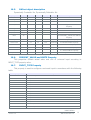
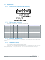
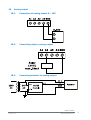
1
iSMA
iSMA-B-MIX18
BACnet
User Manual
iSMA
iSMA-B-MIX18
Version: 1.5
ISM EuroCenter S.A.
1
Table of contents
1. Safety rules................................................................................................................................................ 3
2. Technical specifications ............................................................................................................................ 4
3. Size ............................................................................................................................................................ 5
4. LED Indicators ........................................................................................................................................... 5
5. Grounding and shielding ........................................................................................................................... 6
6. Network Termination ................................................................................................................................ 6
7. Setting Module MAC .................................................................................................................................. 6
8. Setting Device ID ...................................................................................................................................... 7
9. Communication baud rate selection ......................................................................................................... 7
10. Protocol selection ...................................................................................................................................... 7
11. Restoring the default settings .................................................................................................................. 7
12. Connecting the communication bus ......................................................................................................... 8
13. Power supply connection .......................................................................................................................... 8
13.1.
DC power connection ......................................................................................................................... 8
13.2.
AC power connection .......................................................................................................................... 8
14. Protocol implementation conformance statement................................................................................... 9
14.1.
BACnet Protocol Implementation Conformance Statement ..................................................................... 9
14.2.
BACnet Standardized Device Profile ..................................................................................................... 9
14.3.
BACnet Interoperability Building Blocks Supported ................................................................................ 9
14.4.
BACnet Standard Object Types Supported ............................................................................................ 9
14.5.
Data Link Layer Option ....................................................................................................................... 9
14.6.
Character Sets Supported ................................................................................................................... 9
14.7.
Supported Application Services .......................................................................................................... 10
15. Device (iSMA-B-MIX18) .......................................................................................................................... 10
15.1.
BACnet object description ................................................................................................................. 10
15.2.
WATCHDOG property ........................................................................................................................ 11
15.3.
VALID_FRAMES_FOR_US_CNT property ............................................................................................. 11
15.4.
VALID_FRAMES_FOR_NOT_US_CNT property ..................................................................................... 11
15.5.
ERROR_FRAMES_CNT property ......................................................................................................... 11
15.6.
TRANSMITTED_FRAMES_CNT property .............................................................................................. 11
16. Universal Inputs ...................................................................................................................................... 12
16.1.
Connection of universal input to measure voltage 0 – 10V ................................................................... 12
16.2.
Connection of universal input to measure current 0 – 20mA ................................................................. 12
16.3.
Connection of universal input to measure temperature ........................................................................ 13
16.4.
Connection of universal input as a digital input (Dry Contact) ............................................................... 13
16.5.
BACnet object description ................................................................................................................. 14
16.6.
PRESENT_VALUE and UNITS Property ................................................................................................ 14
16.7.
INPUT_TYPE Property ....................................................................................................................... 14
16.8.
FILTER Property ............................................................................................................................... 15
16.9.
RESOLUTION Property ...................................................................................................................... 15
16.10.
VOLTAGE Property ............................................................................................................................ 15
16.11.
RESISTANCE Property ....................................................................................................................... 15
16.12.
DRY_CONTACT Property ................................................................................................................... 15
17. Digital inputs ........................................................................................................................................... 16
17.1.
Connection of digital input (Dry Contact) ............................................................................................ 16
17.2.
BACnet object description ................................................................................................................. 16
17.3.
PRESENT_VALUE Property ................................................................................................................ 16
17.4.
COUNTER Property ........................................................................................................................... 16
18. Analog output .......................................................................................................................................... 17
18.1.
Connection of analog output 0 – 10V ................................................................................................. 17
18.2.
Connecting relay to analog output ..................................................................................................... 17
18.3.
Connecting actuator to analog output ................................................................................................ 17
18.4.
BACnet object description ................................................................................................................. 18
18.5.
PRESENT_VALUE property ................................................................................................................ 18
18.6.
OUTPUT_TYPE Property .................................................................................................................... 18
19. Digital outputs (relays) ........................................................................................................................... 19
19.1.
Connecting the solenoid valve to the digital output.............................................................................. 19
19.2.
Connecting a resistive load to the digital output .................................................................................. 19
19.3.
BACnet object description ................................................................................................................. 20
20. List of objects properties ........................................................................................................................ 20
21. List of supported temperature sensors .................................................................................................. 21
iSMA-B-MIX18
Version: 1.5
ISM EuroCenter S.A.
2
1.
Safety rules.
•
Note incorrect wiring of this product can damage it and lead to other hazards. Make
sure the product has been correctly wired before turning the power ON.
•
Before wiring, or removing / mounting the product, be sure to turn the power OFF.
Failure to do so might cause electric shock.
•
Do not touch electrically charged parts such as the power terminals. Doing so might
cause electric shock.
•
Do not disassemble the product. Doing so might cause electric shock or faulty
operation.
•
Use the product within the operating ranges recommended in the specification
(temperature, humidity, voltage, shock, mounting direction, atmosphere etc.).
Failure to do so might cause fire or faulty operation
•
Firmly tighten the wires to the terminal. Insufficient tightening of the wires to the
terminal might cause fire.
iSMA-B-MIX18
Version: 1.5
ISM EuroCenter S.A.
3
2.
Technical specifications
Power supply
Universal Inputs
Digital Inputs
Analog Outputs
Digital Outputs (relays)
Voltage
24V AC/DC ± 20%
Power consumption
3W @ 24VDC; 4.5VA @ 24VAC
No. of inputs
5
Temperature input
Measurement with attached RTDs
accuracy 0.1˚C
Voltage input
Voltage measurement from 0 to 10V
Input impedance 100kΩ
measurement accuracy ±1mV
Resistive input
Measurement of resistance from 0 to 1000kΩ
Resistance measurement method
The voltage divider
Dry contact input
Output current ~1mA
Measurement resolution
12 bits (default) or 16 bits
Processing time
10ms/channel at 12 bits
140ms/ channel at 16 bits
No. of inputs
5
Type
Dry contact
Max input frequency
100Hz
No. of outputs
4
Voltage range
0 to 10V
Max. load current
20mA
Resolution
12 bits
Accuracy
±0.5%
No. of outputs
4
Resistive load
3A @ 230VAC or 3A @ 30VDC
Inductive load
75VA @ 230VAC or 30W @ 30VDC
RS485
Up to 128 devices
Communication protocol
Modbus RTU, Modbus ASCII,
BACnet or BACnet SLAVE set by switch
Baud rate
From 2400 to 115200
set by switch
Address
0 to 99
set by switch
Ingress protection
IP
IP40
Temperature
Storage
– 40˚C to +85˚C
Operating
– 10˚C to +50˚C
Humidity
Relative
5 to 95%
Connectors
Type
Removable
Maximum cable size
2.5 mm2
Width
110 mm
Length
88 mm
Height
62 mm
Interface
Dimension
iSMA-B-MIX18
Version: 1.5
ISM EuroCenter S.A.
4
3.
Size
4.
LED Indicators
•
The power LED is ON (green) when the module is running properly.
•
Communication LED is ON (orange) for 20 ms after sending each message. If the
module receives / sends a lot of messages LED can be lit continuously.
•
LEDs indicate the status of the universal inputs are lit when resistance connected to
the input is less than 1kΩ (Dry Contact input is active). Caution! The LED also lights
up when voltage connected to the input has a very low potential.
•
LEDs indicate the status of the digital inputs are lit when the input is active.
•
LEDs indicate the status of the analog outputs are lit when output voltage or PWM
factor is different from 0.
•
LEDs indicate the status of the digital outputs are lit when output is enabled.
iSMA-B-MIX18
Version: 1.5
ISM EuroCenter S.A.
5
5.
Grounding and shielding
In most cases, IO modules will be installed in an enclosure along with other devices
which generate electromagnetic radiation. Examples of these devices are relays,
contactors, transformers, motor invertors etc. This electromagnetic radiation can induce
electrical noise into both power and signal lines, as well as direct radiation into the module
causing negative effects on the system. Appropriate grounding, shielding and other
protective steps should be taken at the installation stage to prevent these effects. These
protective steps include control cabinet grounding, cable shield grounding, protective
elements for electromagnetic switching devices, correct wiring as well as consideration of
cable types and their cross sections.
6.
Network Termination
Transmission line effects often present a problem on data communication networks.
These problems include reflections and signal attenuation.
To eliminate the presence of reflections from the end of the cable, the cable must
be terminated at both ends with a resistor across the line equal to its characteristic
impedance. Both ends must be terminated since the direction of propagation is
bidirectional. In the case of an RS485 twisted pair cable this termination is typically 120 Ω.
7.
Setting Module MAC
To determine the MAC of module, module provides two rotary switches S1 and S2
located on the top panel device.
It is possible to set the MAC from 0 to 99 in BACnet protocol mode
or from 128 to 227 in BACnet SLAVE protocol mode (128 + switch value).
Changing the MAC address is instantaneous. No restart is required.
The formula for setting the MAC:
MAC = S2 • 10 + S1
Where S1 and S2 are values of switches.
Example for BACnet protocol mode:
Switch sets as in the picture above will set the module MAC to 11.
Example for BACnet SLAVE protocol mode:
Switch sets as in the picture above will set the module MAC to 139 (128+11).
iSMA-B-MIX18
Version: 1.5
ISM EuroCenter S.A.
6
8.
Setting Device ID
Formula for Device ID:
DeviceID = VendorID*1000 + MAC + 128(Only in BACnet SLAVE)
Where VendorID = 680.
Example: If MAC is set to 41 and BACnet protocol than DeviceID = 680041 or if in
BACnet SLAVE than DeviceID = 680169
If user change Device ID (by setting a new value of Device ID property in Device object)
then change of MAC does not change Device ID. Restore the default behaviour occurs with
the restoration of the default settings (11 Błąd! Nie można odnaleźć źródła odwołania.).
9.
Communication baud rate selection
Transmission baud rate is determined by S3 switch (sections 1, 2 and 3) in
accordance with the following table:
1
10.
2
OFF (0)
OFF (0)
OFF (0)
OFF (0)
3
Baud rate
OFF (0)
76800
OFF (0)
ON (1)
2400
ON (1)
OFF (0)
4800
OFF (0)
ON (1)
ON (1)
9600
ON (1)
OFF (0)
OFF (0)
19200
ON (1)
OFF (0)
ON (1)
38400
ON (1)
ON (1)
OFF (0)
57600
ON (1)
ON (1)
ON (1)
115200
Protocol selection
Protocol selection is done by sections 4 and 5 of the S3 switch according to
following table:
1
4
5
Protocol
OFF (0)
OFF (0)
Modbus RTU
OFF (0)
ON (1)
Modbus ASCII
ON (1)
OFF (0)
BACnet
ON (1)
ON (1)
BACnet SLAVE
1
BACnet SLAVE does not support discover function.
11.
Restoring the default settings
To restore the default configuration of all registers, follow the steps below:
1.
Turn off power supply
2.
Set section 6 of S3 switch to ON
3.
Turn on power supply, power LED blinking
4.
Switch section 6 of S3 switch to OFF to restore the default settings. To cancel the
reset, turn off the power and switch section 6 of S3 switch to the OFF position.
iSMA-B-MIX18
Version: 1.5
ISM EuroCenter S.A.
7
12.
Connecting the communication bus
13.
Power supply connection
13.1.
DC power connection
13.2.
AC power connection
iSMA-B-MIX18
Version: 1.5
ISM EuroCenter S.A.
8
14.
Protocol implementation conformance statement
14.1.
14.2.
BACnet Protocol Implementation Conformance Statement
Date
2013-09-26
Vendor Name
ISM EuroCenter S.A.
Product Name
iSMA-B-MIX
Product Model Number
iSMA-B-MIX18
Firmware Revision
0.8.0
BACnet Protocol Revision
1.12
BACnet Standardized Device Profile
BACnet Smart Sensor (B-SS)
14.3.
14.4.
BACnet Interoperability Building Blocks Supported
Application Service (B-SS)
Designation
Data Sharing - Read Property - B
DS-RP-B
Data Sharing - Write Property - B
DS-WP-B
Device Management - Dynamic Device Binding - B
DM-DDB-B
Device Management - Dynamic Object Binding - B
DM-DOB-B
Data Sharing - Read Property Multiple - B
DS-RPM-B
Data Sharing - Write Property Multiple - B
DS-WPM-B
BACnet Standard Object Types Supported
The following is a list of the standard object types as defined by ASHRAE.
14.5.
Object Name
Object Numbers
Analog Input
5
Analog Output
4
Binary Input
5
Binary Output
4
Device
1
Data Link Layer Option
Master-Slave/Token-Passing (MS/TP) master (Clause 9), baud rates: 2400, 4800,
9600, 19200, 38400, 57600, 76800, 115200.
14.6.
Character Sets Supported
ANSI X3.4
iSMA-B-MIX18
Version: 1.5
ISM EuroCenter S.A.
9
14.7.
Supported Application Services
Application Service Initiates Requests Executes Requests
15.
I-Am
yes
I-Have
yes
ReadProperty
yes
ReadPropertyMultiple
Yes
Who-Has
yes
Who-Is
yes
WriteProperty
yes
WritePropertyMultiple
yes
Device (iSMA-B-MIX18)
15.1.
BACnet object description
Dynamically Creatable: No, Dynamically Deletable: No
Property Name
Required Proprietary Writeable Property ID Data Type
OBJECT_IDENTIFIER
yes
OBJECT_NAME
yes
OBJECT_TYPE
yes
SYSTEM_STATUS
yes
VENDOR_NAME
yes
VENDOR_IDENTIFIER
yes
MODEL_NAME
yes
FIRMWARE_REVISION
yes
APPLICATION_SOFTWARE_VERSION
yes
PROTOCOL_VERSION
yes
PROTOCOL_REVISION
yes
PROTOCOL_SERVICES_SUPPORTED
yes
PROTOCOL_OBJECT_TYPES_SUPPORTED
yes
OBJECT_LIST
yes
MAX_APDU_LENGTH_ACCEPTED
yes
SEGMENTATION_SUPPORTED
yes
APDU_TIMEOUT
yes
NUMBER_OF_APDU_RETRIES
yes
MAX_MASTER
yes
MAX_INFO_FRAMES
yes
DEVICE_ADDRESS_BINDING
yes
DATABASE_REVISION
yes
Description
iSMA-B-MIX18
yes
WATCHDOG
yes
VALID_FRAMES_FOR_US_CNT
yes
5001
Unsigned
yes
5101
Unsigned
VALID_FRAMES_NOT_FOR_US_CNT
yes
5102
Unsigned
ERROR_FRAMES_CNT
yes
5103
Unsigned
TRANSMITTED_FRAMES_CNT
yes
5104
Unsigned
15.2
WATCHDOG
property
iSMA-B-MIX18
Version: 1.5
ISM EuroCenter S.A.
10
15.2.
WATCHDOG property
This property specifies the time in seconds to watchdog reset. If module does not
receive any valid BACnet message within that time, all PRIORITY_ARRAYs will be set to
null and PRESENT_VALUE for outputs will be set to RELINQUISH_DEFAULT value.
This feature is useful if for some reason there is an interruption in data transmission
and for security reasons output states must be set to the appropriate state endanger the
safety of persons or property.
A setting of 0 will disable the watchdog. The default value is 15 seconds.
15.3.
VALID_FRAMES_FOR_US_CNT property
This property contains number of valid frames (on MS/TP layer) addressed to this
module.
15.4.
VALID_FRAMES_FOR_NOT_US_CNT property
This property contains number of valid frames (on MS/TP layer) but not addressed
to this module.
15.5.
ERROR_FRAMES_CNT property
This property contains number of invalid frames on MS/TP layer.
15.6.
TRANSMITTED_FRAMES_CNT property
This property contains number of transmitted frames.
iSMA-B-MIX18
Version: 1.5
ISM EuroCenter S.A.
11
16.
Universal Inputs
16.1.
Connection of universal input to measure voltage 0 – 10V
16.2.
Connection of universal input to measure current 0 – 20mA
iSMA-B-MIX18
Version: 1.5
ISM EuroCenter S.A.
12
16.3.
Connection of universal input to measure temperature
16.4.
Connection of universal input as a digital input (Dry Contact)
iSMA-B-MIX18
Version: 1.5
ISM EuroCenter S.A.
13
16.5.
BACnet object description
Dynamically Creatable: No, Dynamically Deletable: No
Property Name
Required Proprietary Writeable Property ID Data Type
OBJECT_IDENTIFIER
yes
OBJECT_NAME
yes
OBJECT_TYPE
yes
PRESENT_VALUE
yes
STATUS_FLAGS
yes
EVENT_STATE
yes
OUT_OF_SERVICE
yes
UNITS
yes
Description
from UI-1 to UI-5
16.6
PRESENT_VALUE and UNITS
Property
16.6
PRESENT_VALUE and UNITS
Property
INPUT_TYPE
yes
yes
4001
Enumerated
16.7
INPUT_TYPE Property
RESOLUTION
yes
yes
4002
Enumerated
16.9
RESOLUTION Property
FILTER
yes
yes
4003
Unsigned
VOLTAGE
yes
3010
Unsigned
RESISTANCE
yes
3012
Unsigned
DRY_CONTACT
yes
3013
Enumerated
16.6.
16.8
16.10
16.11
16.12
FILTER Property
VOLTAGE Property
RESISTANCE Property
DRY_CONTACT Property
PRESENT_VALUE and UNITS Property
This properties contain actual value and unit of universal input according to
INPUT_TYPE property value.
16.7.
INPUT_TYPE Property
This property is used to configure a universal input in accordance with the following
table:
Property value
0
Description
Voltage measuring 0-10V
1 (default)
The temperature sensor 10K3A1 NTC B=3975K
2
The temperature sensor 10K4A1 NTC B=3695K
3
The temperature sensor 10K NTC B=3435K Carel
4
The temperature sensor 20K6A1 NTC B=4262K
5
The temperature sensor 2,2K3A1 NTC B=3975K
6
The temperature sensor 3K3A1 NTC B=3975K
7
The temperature sensor 30K6A1 NTC B=4262K
8
The temperature sensor SIE1
9
The temperature sensor TAC1
10
The temperature sensor SAT1
16
The temperature sensor Pt1000
17
The temperature sensor Ni1000
254
Resistance input
255
Dry Contact input
iSMA-B-MIX18
Version: 1.5
ISM EuroCenter S.A.
14
16.8.
FILTER Property
Property with a time constant low pass filter. The value is expressed in seconds.
Valid values must be between 0 and 60 seconds. The default filter value is 2 seconds.
16.9.
RESOLUTION Property
This property is used to determine the bit resolution for each universal input.
Setting the value to 0 will set the resolution of converter to 12 bit. Setting the value
to 1 sets the resolution of converter to 16-bit.
Caution! Setting 16-bit resolution increases measurement time of one channel
from 10ms to 140ms. Total time taken to measure all the channels increases from 80ms to
1120ms.
16.10.
VOLTAGE Property
Value of this property is the results of the voltage measurement for input. The
result is expressed in mV.
16.11.
RESISTANCE Property
Value of this property is the results of the resistance measurement for input. The
result is expressed in Ω.
16.12.
DRY_CONTACT Property
Value of this property contains information about the status of digital inputs (dry
contact). Short the input to ground will set value to 1.
iSMA-B-MIX18
Version: 1.5
ISM EuroCenter S.A.
15
17.
Digital inputs
17.1.
Connection of digital input (Dry Contact)
17.2.
BACnet object description
Dynamically Creatable: No, Dynamically Deletable: No
Property Name
Required Proprietary Writeable Property ID Data Type
OBJECT_IDENTIFIER
yes
OBJECT_NAME
yes
OBJECT_TYPE
yes
PRESENT_VALUE
yes
STATUS_FLAGS
yes
EVENT_STATE
yes
OUT_OF_SERVICE
yes
POLARITY
yes
UNITS
yes
COUNTER
17.3.
Description
from DI-1 to DI-5
17.3
yes
yes
3001
unsigned
PRESENT_VALUE Property
17.4
COUNTER Property
PRESENT_VALUE Property
This property contains the status of the digital inputs. Short-circuiting the input to GND sets the
value to 1.
17.4.
COUNTER Property
This property contains number of counted pulses.
In the case you would like to change the value of the property you can write any
value (called preset). In the particular case, you can reset the counter by entering 0.
iSMA-B-MIX18
Version: 1.5
ISM EuroCenter S.A.
16
18.
Analog output
18.1.
Connection of analog output 0 – 10V
18.2.
Connecting relay to analog output
18.3.
Connecting actuator to analog output
iSMA-B-MIX18
Version: 1.5
ISM EuroCenter S.A.
17
18.4.
BACnet object description
Dynamically Creatable: No, Dynamically Deletable: No
Property Name
Required
OBJECT_IDENTIFIER
yes
OBJECT_NAME
yes
OBJECT_TYPE
yes
PRESENT_VALUE
yes
Proprietary
Writeable
Property ID Data Type
Description
from AO-1 to AO-4
yes
18.5
PRESENT_VALUE property
STATUS_FLAGS
yes
EVENT_STATE
yes
OUT_OF_SERVICE
yes
UNITS
yes
PRIORITY_ARRAY
yes
RELINQUISH_DEFAULT
yes
OUTPUT_TYPE
18.5.
yes
yes
yes
4001
enumerated
18.6
OUTPUT_TYPE
Property
PRESENT_VALUE property
In the property is stored value in mV of voltage that appears at the analog output.
If OUTPUT_TYPE Property is set to PWM than PRESENT_VALUE contains duty cycle (in percentage) of
output PWM signal.
18.6.
OUTPUT_TYPE Property
This property contain information about the mode of the analog output according to following
table:
Property value
Description
0 (default)
Voltage output 0 – 10V
1
PWM 1Hz
2
PWM 10Hz
3
PWM 100Hz
iSMA-B-MIX18
Version: 1.5
ISM EuroCenter S.A.
18
19.
Digital outputs (relays)
19.1.
Connecting the solenoid valve to the digital output
19.2.
Connecting a resistive load to the digital output
iSMA-B-MIX18
Version: 1.5
ISM EuroCenter S.A.
19
19.3.
BACnet object description
Dynamically Creatable: No, Dynamically Deletable: No
Property Name
Required
OBJECT_IDENTIFIER
yes
OBJECT_NAME
yes
OBJECT_TYPE
yes
PRESENT_VALUE
yes
STATUS_FLAGS
yes
EVENT_STATE
yes
OUT_OF_SERVICE
yes
POLARITY
yes
PRIORITY_ARRAY
yes
RELINQUISH_DEFAULT
yes
20.
Proprietary
Writeable
Property ID Data Type
Description
from DO-1 to DO-12
yes
yes
List of objects properties
Object
Property Name
Writeable
Property ID
Data Type
Description
WATCHDOG
Yes
5001
Unsigned
Time in seconds to watchdog reset.
VALID_FRAMES_FOR_US_CNT
Device
VALID_FRAMES_NOT_FOR_US_CNT
(iSMA-B-MIX18)
ERROR_FRAMES_CNT
TRANSMITTED_FRAMES_CNT
5101
Unsigned
Number of valid frames addressed to module
5102
Unsigned
Number of valid frames but not addressed to module
5103
Unsigned
Number of invalid frames
5104
Unsigned
Number of transmitted frames
Measured value of universal input according to
INPUT_TYPE property value.
PRESENT_VALUE
Used to configure a universal input in accordance
Universal Input
(UI-1 ÷ UI-5)
yes
4001
Enumerated
RESOLUTION
yes
4002
Enumerated
Resolution of converter:
0 – 12 bits
1 – 16 bits
FILTER
yes
4003
Unsigned
Lowpass filter time constant in seconds
VOLTAGE
3010
Unsigned
Universal input voltage in mV
RESISTANCE
3012
Unsigned
Universal input resistance in Ω
Enumerated
Status of digital input (dry contact).
Short the input to ground will set value to 1.
DRY_CONTACT
Digital Input
(DI-1 ÷ DI-5)
INPUT_TYPE
Property
with the table in 16.7
INPUT_TYPE
3013
Status of the digital inputs.
Short the input to ground will set value to 1.
PRESENT_VALUE
COUNTER
PRESENT_VALUE
yes
3001
Unsigned
Number counted of pulses
Analog output value in mV if OUTPUT_TYPE set to 0
Analog output value in % if OUTPUT_TYPE set to 1-3
yes
Mode of the analog output according to following
table:
Analog Output
(AO-1 ÷ AO-4)
Digital Output
(DO-1 ÷ DO-4)
OUTPUT_TYPE
PRESENT_VALUE
yes
yes
4001
Enumerated
Property value
Description
0 (default)
Voltage output 0 – 10V
1
PWM 1Hz
2
PWM 10Hz
3
PWM 100Hz
State of digital output
iSMA-B-MIX18
Version: 1.5
ISM EuroCenter S.A.
20
21. List of supported temperature sensors
No
1
No
2
Sensor
10K3A1
Sensor
10K4A1
β coeffictient
3975K
β coeffictient
3695K
Manufacturers
Aquatrol, Cylon, Honeywell, Johnson, Satchwell, Seachange
Manufacturers
Andover, Delta Controls, Siebe,
York
°C
Ω
°C
Ω
–50
667828
–50
441667
-45
491749
-45
330749
–40
335671
–40
239831
-35
241840
-35
181532
–30
176683
–30
135233
-25
131251
-25
105081
–20
96974
–20
78930
–15
72895
–15
61030
–10
55298
–10
47549
–5
42314
–5
37316
0
32650
0
29490
5
25396
5
23462
10
19904
10
18787
15
15714
15
15136
20
12494
20
12268
25
10000
25
10000
30
8056
30
8197
35
6530
35
6754
40
5325
40
5594
45
4367
45
4656
50
3601
50
3893
55
2985
55
3271
60
2487
60
2760
65
2082
65
2339
70
1751
70
1990
75
1480
75
1700
80
1256
80
1458
85
1070
85
1255
90
916
90
1084
95
787
95
939
100
678
100
817
105
587
105
713
110
510
110
624
115
444
115
547
120
388
120
482
125
340
125
426
iSMA-B-MIX18
Version: 1.5
ISM EuroCenter S.A.
21
No
3
No
4
Sensor
10K Carel
Sensor
20K6A1
β coeffictient
3435K
β coeffictient
4262K
–50
329500
Manufacturers
Honeywell
-45
247700
°C
Ω
–40
188500
–40
806800
-35
144100
-35
574400
–30
111300
–30
413400
-25
86430
-25
300400
–20
67770
–20
220600
–15
53410
–15
163480
–10
42470
–10
122260
–5
33900
–5
92220
0
27280
0
70140
5
22050
5
53780
10
17960
10
41540
15
14690
15
32340
20
12090
20
25340
25
10000
25
20000
30
8313
30
15886
35
6940
35
12698
40
5827
40
10212
45
4912
45
8260
50
4161
50
6718
55
3536
55
5494
60
3020
60
4518
65
2588
65
3732
70
2228
70
3098
75
1924
75
2586
80
1668
80
2166
85
1451
85
1823
90
1266
90
1541
95
1108
95
1308
100
973
100
1114
105
857
105
953
110
758
110
818
115
672
115
704
120
597
120
609
125
531
125
528
iSMA-B-MIX18
Version: 1.5
ISM EuroCenter S.A.
22
No
5
No
6
Sensor
2.2K3A1
Sensor
3K3A1
β coeffictient
3975K
β coeffictient
3975K
Manufacturers
Ambiflex, Johnson
Manufacturers
Alerton
°C
Ω
°C
Ω
–50
329500
–50
200348
-45
247700
-45
150524
–40
188500
–40
100701
-35
144100
-35
76853
–30
111300
–30
53005
-25
86430
-25
41048
–20
67770
–20
29092
–15
53410
–15
21868
–10
42470
–10
16589
–5
33900
–5
12694
0
27280
0
9795
5
22050
5
7619
10
17960
10
5971
15
14690
15
4714
20
12090
20
3748
25
10000
25
3000
30
8313
30
2417
35
6940
35
1959
40
5827
40
1598
45
4912
45
1310
50
4161
50
1080
55
3536
55
896
60
3020
60
746
65
2588
65
625
70
2228
70
526
75
1924
75
444
80
1668
80
377
85
1451
85
321
90
1266
90
275
95
1108
95
236
100
973
100
204
105
857
105
176
110
758
110
153
115
672
115
133
120
597
120
117
125
531
125
102
iSMA-B-MIX18
Version: 1.5
ISM EuroCenter S.A.
23
No
7
No
8
Sensor
30K6A1
Sensor
SIE1
β coeffictient
4262K
Manufacturers
Barber Colman, Siebe
Manufacturers
Drayton
°C
Ω
°C
Ω
–50
10732
–30
622911
-45
10624
-25
477393
–40
10517
–20
331876
-35
10344
–15
245785
–30
10172
–10
183697
-25
9913
–5
138502
–20
9654
0
105305
–15
9320
5
60713
–10
8933
10
62347
–5
8496
15
48511
0
8044
20
38019
5
7489
25
30000
10
6938
30
23828
15
6370
35
19046
20
5798
40
15317
25
5238
45
12390
30
4696
50
10079
35
4185
55
8243
40
3707
60
6777
45
3271
65
5600
50
2875
70
4650
55
2521
75
3879
60
2206
80
3251
65
1929
85
2737
70
1685
90
2313
75
1472
95
1963
80
1287
100
1672
85
1127
105
1430
90
986
110
1228
95
866
115
1058
100
760
120
915
105
670
125
793
110
590
115
522
120
462
125
410
iSMA-B-MIX18
Version: 1.5
ISM EuroCenter S.A.
24
No
9
No
10
Sensor
TAC1
Sensor
SAT1
β coeffictient
3500K
Manufacturers
Satchwell
Manufacturers
TAC
°C
Ω
°C
Ω
–50
9719
–40
39024
-45
9652
-35
29358
–40
9584
–30
22284
-35
9467
-25
17073
–30
9349
–20
13192
-25
9159
–15
10276
–20
8968
–10
8068
–15
8708
–5
6382
–10
8396
0
5085
–5
8031
5
4078
0
7614
10
3294
5
7150
15
2676
10
6649
20
2188
15
6121
25
1800
20
5580
30
1488
25
5039
35
1237
30
4513
40
1034
35
4012
45
869
40
3545
50
733
45
3117
55
622
50
2730
60
529
55
2386
65
453
60
2082
70
389
65
1816
75
335
70
1585
80
290
75
1385
85
252
80
1213
90
220
85
1064
95
192
90
937
100
169
95
828
105
149
100
734
110
131
105
654
115
116
110
585
120
103
115
525
125
92
120
474
125
429
iSMA-B-MIX18
Version: 1.5
ISM EuroCenter S.A.
25
No
16
No
16
Sensor
Pt1000
Sensor
Pt1000
Manufacturers
Honeywell, Sauter, Serck, Siebe,
Cylon
Manufacturers
Honeywell, Sauter, Serck, Siebe,
Cylon
°C
Ω
°C
Ω
-50
803
310
2156
-40
843
320
2192
-30
882
330
2227
-20
922
340
2262
-10
961
350
2297
0
1000
360
2332
10
1039
370
2367
20
1078
380
2402
30
1117
390
2436
40
1155
400
2471
50
1194
60
1232
No
17
70
1271
Sensor
Ni1000
80
1309
Manufacturers
Sauter
90
1347
°C
Ω
100
1385
-50
743
110
1423
-40
791
120
1461
-30
841
130
1498
-20
893
140
1536
-10
946
150
1573
0
1000
160
1611
10
1056
170
1648
20
1112
180
1685
30
1171
190
1722
40
1230
200
1759
50
1291
210
1795
60
1353
220
1832
70
1417
230
1868
80
1483
240
1905
90
1549
250
1941
100
1618
260
1977
110
1688
270
2013
120
1760
280
2049
130
1833
290
2085
140
1909
300
2121
150
1987
iSMA-B-MIX18
Version: 1.5
ISM EuroCenter S.A.
26