1
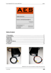
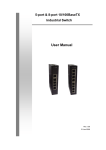
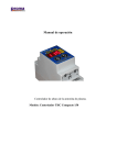
Operation Manual
Plasma torch height controller.
Model: Compact THC Controller 150
Notes on safety
WHEN THE DEVICE IS IN OPERATION, VOLTAGE HAZARDOUS
TO HEALTH AND HUMAN LIFE IS PRESENT INSIDE THE
HOUSING AND AT THE CONNECTION TERMINALS
The device should be connected only by a qualified and authorized person.
Improper connection can cause serious injury or death. Prior to installation and
operating, carefully read the entire installation and maintenance manual and be
absolutely sure, you full understand and are able to make the sole decision to
determine if you are capable of a safe and proper installation. Remember that,
inside the device and at the connection terminals, voltage hazardous to health
and life may be present.
The following actions, although not all inclusive, should be strictly adhered to:
Installation of this product by an unqualified individual should not be done.
No physical contact with any electrical connections while under power.
Do not operate this product with wet hands, wet gloves, or any wet clothing.
Before turning the unit on, secure the safety of others, and read and understand
all instructions. If you have any questions or concerns, do not continue.
Warning: Provide adequate protection for all risks associated with plasma cutting.
For more detailed information of the risk associated with plasma cutting, refer to
your plasma cutter's owner manual.
Touching non-insulated and non-grounded elements can be fatal. Provide a safe
place for your device. After assembly, secure protection of contact terminals from
operator's touch.
It is strictly prohibited to perform any repairs or modifications to this product! Performing either one of these actions could lead to serious injury or death to
yourself and/or others.
Terms of Use: By proceeding with installation and use of this product, you fully
understand and agree Proma-Elektronika nor their distributors, are not liable for
any incident or event resulting in direct loss, indirect loss, injury to self or others,
damage to property, or loss or damage of any kind. End user assumes all risks.
If you do not agree to these terms in it's entirety, proceed no further, and return
this product for a full refund.
If you have any questions or are unsure about anything stated in this
manual problem, immediately contact a Proma-Elektronika dealer or service
centre for assistance.
2
Device Information
The unit is a modern analogue - microprocessor plasma torch height
controller that operates by analyzing voltage changes in the plasma source due
to variations in height between the torch tip and the material being cut. The
microprocessor makes determinations to raise or lower the torch based off of the
strength of the voltage signal being read. It is equipped with an easy to read
LED display and two user friendly keys making operation simple and does not
require any additional measuring instruments. The device has patented solutions
made with the highest quality components to ensure a safe, durable, and reliable
long-term operation.
Simplified block diagram:
Pilot Arc Voltage Neutraliser - protection system, which is responsible for
removing spikes in the AC electrical flow, which can be caused by a plasma
source with contact-less arc striking (HV/HF pilot arc) generating a high voltage
or from surges coming from plasma cutters equipped with contact arc striking
system.
Main Arc Voltage Divider – While in operation, the cutter generates dangerous
voltage levels, unsafe for precision electronics. A voltage divider system is
incorporated to reduce this voltage to a safe level.
A quick acting filter system removes any interference that may pass through a
voltage divider.
Filtered and scaled voltage values derived from the plasma cutter's “raw arc
voltage” are then sent to the brain of the device. The "brain" consists of a
programmed microprocessor, which in addition to the analysis of the cutting
voltage parameters and proper output blocks controlling, also supports the LED
display and function keys.
A built-in switching power supply ensures compatibility in a wide range of power
supply voltages without the need for heat sinking. The power supply connection
is optically isolated from the rest of the system which allows you to use to share
power from existing systems providing they output the recommended voltage.
The last block is a relay output circuit, to which the driver/PC inputs are
connected, which is responsible for Z-axis motor control of the CNC plasma
cutter.
3
The main parameters of the device:
Parameter name
Acceptable
Supply voltage (V)
7 – 35V DC
Maximum input current
120mA
Maximum direct input voltage
300VDC
Maximum input voltage of 1:50 divider
10VDC
Ability to eliminate HV/HF ionizing voltage
0.3kVAC
Ability to eliminate HV/HF ionizing frequency
>100kHz
Duty cycle (%)
100%
Duty Cycle of HV/HF elimination (%)
100%
Capacity of relays
50mA / 60V DC
Life of used relays (declared minimum switching) with a 500 000
000
capacity of 5V/10mA
cycles
Degree of protection
IP20
Weight (g)
130g
External Dimensions (L * W * H) [mm]
33*89*65
Mounting
DIN35 rail
TEST*
36VDC*
1000V DC*
60V DC*
30kV AC*
75kHz
-
* Tested in the laboratory.
Power Connection:
Optional power supply 35-50V:
For lower limit switches of the device, one can lead full output voltage of
plasma source. In this connection do not connect anything to the other input
terminals of the controller.
When connecting directly, use the shortest possible cables for connecting
the plasma source with THC controller - it is recommended the THC controller to
be located directly at the plasma source.
4
While being a universal THC, accepting full raw arc voltage for most any
plasma cutter on the market, an exciting new standard feature of this unit is the
addition of a 1:50 divider for an extremely fast, simple installation on most major
brands. There will most likely be a direct connection for this on the outside of the
plasma cutter's unit. Please refer to your plasma cutter owner's manual.
An example of how to connect the THC controller's measurement input with
the output of the very popular Hypertherm Powermax45® - The THC comes
standard equipped with a low voltage output of 1:50 divider. This ratio is the
most commonly used division in most major brands and there will most likely be
a plug for this connection on the outside of the cutter's unit.
Description of relay outputs:
The relay outputs “Arc, Up, Down”, are controlling outputs via relays, and should
not be utilized for anything other then it's intended use.
COM terminal is a common input terminal connected to the ARC, UP and DOWN
relay contacts inside the device, according to the diagram located on the cover
(above picture). Suggested route is to “GND” at driver/pc end. Do not jumper
this connection to the “7-35V” negative.
ARC output (also known as “Arc Okay”) is activated when plasma ignition is
detected. Route and configure for a software input. Not required to operate.
5
UP output is activated when the measured voltage is lower than the voltage
setpoints, reduced by half the hysteresis voltage. Route and configure for a
software input.
DOWN output is activated when the measured voltage is higher than the voltage
setpoints, reduced by half the hysteresis voltage. Route and configure for a
software input.
Note: No output relays are activated in case when only the pilot arc is detected
and when the main arc is broken.
Relay outputs should be connected to the CNC system in accordance with the
documentation of the CNC electronic system controlling the machine. For this,
we use inputs of outermost connectors HOME or LIMIT - THC relay contacts
should be connected to the terminals the same way as limit switches connectors.
At the same time, the common COM terminal relay should be connected to the
CNC system to a common terminal for limit switches (it is usually a GND
terminal).
To reduce the possibility of the short-circuit entering the CNC system, the
connection should be made with a shielded cable - the shielding must be
connected to grounding on the CNC system side. Do not connect the shielding to
the THC controller side.
6
Start-up and operation:
The device is pre-configured at the factory and after the correct
connections are made, it immediately works properly with most plasma devices.
After switching power on, the THC controller's display shows an "animated" "thc"
message, and then a flashing voltage value is presented for 1 second; the device
is undergoing automatic calibration at this moment.
When the device is ready for operation it displays "- - - " which means, that there
is no input voltage.
In this state, by depressing both the up/down keys, simutaneously and holding
for a few seconds, the voltage setpoints can be modified and thus set the torch's
height above the material. Press shortly once to display the set value without
modification.
To determine other parameters simultaneously hold both keys until you see the
desired parameter on the display - when you release the keys, its value will be
displayed - using the up/down keys to set the desired value:
"HYS" (Hysteresis) - The hysteresis voltage - a range in
which the voltage is measured, in which there are signals
controlling UP/DOWN 2-30V (±1V - ±15V) - factory setting: 8V
(±4V)
"d - t" (delay time) - delay time of output closed despite no
supply voltage, when the system detects the main (cutting) arc
0.1 - 9.9s factory setting: 0.5s
"H - U" (High Voltage) - value of the off load voltage detection
in the plasma cutter - used to detect the main (cutting) arc: 50300V by default: 200V
"tSt" (Test) - Simulation of the controller's work - the system
simulates the appearance of "floating" voltage within the
selected value - causes the activation of inputs for easy
system testing without switching the cutter on.
When the plasma cutter is switching on, the display presents the measured
voltage value and LED diodes present the current status of outputs. Fast blinking
of the measured value indicates the detection of pilot arc; continuous display
indicates the detection of the main (cutting) arc.
All parameters can be modified during operation; these changes are reflected in
real time in the control of output signals.
7