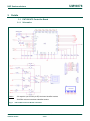
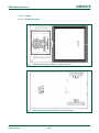
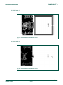
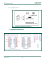
1
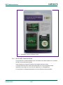
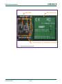
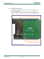
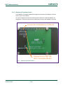
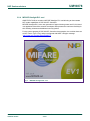
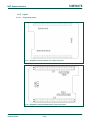
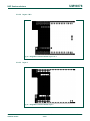
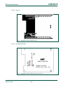
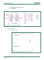
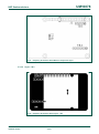
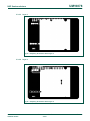
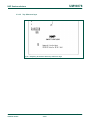
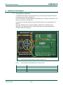
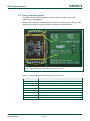
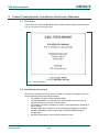
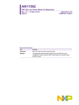
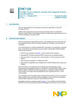
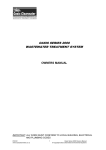
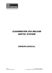
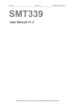
UM10878 PN7120 NFC Controller SBC Kit User Manual Rev. 1.1 — 7 October 2015 318511 User manual COMPANY PUBLIC Document information Info Content Keywords OM5577, PN7120, Demo kit, Raspberry Pi, BeagleBone Abstract This document is the user manual of the PN7120 NFC Controller SBC kit. UM10878 NXP Semiconductors PN7120 NFC Controller SBC Kit User Manual Revision history Rev Date 1.1 1.0 20151007 20150519 Description • FCC statement added • Note about useless of some components on the schematics added • Section 7.3 Licenses updated First release Contact information For more information, please visit: http://www.nxp.com UM10878 User manual COMPANY PUBLIC All information provided in this document is subject to legal disclaimers. Rev. 1.1 — 7 October 2015 318511 © NXP Semiconductors N.V. 2015. All rights reserved. 2 of 28 UM10878 NXP Semiconductors PN7120 NFC Controller SBC Kit User Manual 1. Introduction The present document describes the OM5577/PN7120S demonstration kit, a flexible and easy-to-use Single Board Computer (SBC) Kit for the PN7120 NFC Controller. It contains a PN7120 NFC Controller Board, a Raspberry Pi Interface Board, a BeagleBone Interface Board, as well as an NFC Forum Type 2 Tag in form of a MIFARE UL Card. It enables the development of an NFC solution based on PN7120 in a Linux or Android environment. PN7120 is a full NFC controller solution with integrated firmware and NCI interface designed for contactless communication at 13.56 MHz. This document presents first an overview of the kit. Then, it gives printed circuit boards details. Finally, it provides information for reuse of the kit in different environments. UM10878 User manual COMPANY PUBLIC All information provided in this document is subject to legal disclaimers. Rev. 1.1 — 7 October 2015 318511 © NXP Semiconductors N.V. 2015. All rights reserved. 3 of 28 UM10878 NXP Semiconductors PN7120 NFC Controller SBC Kit User Manual 2. Overview 2.1 Kit description OM5577/PN7120S kit is a high performance fully NFC compliant expansion board for both Raspberry Pi (refer to [1] for more details) and BeagleBone (refer to [2] for more details). It meets compliance with Reader mode, P2P mode and Card emulation mode standards. The board features an integrated high performance RF antenna to insure high interoperability level with NFC devices. 2.2 Kit content The kit is composed of 3 printed circuit boards and a MIFARE Ultralight EV1 card. UM10878 User manual COMPANY PUBLIC All information provided in this document is subject to legal disclaimers. Rev. 1.1 — 7 October 2015 318511 © NXP Semiconductors N.V. 2015. All rights reserved. 4 of 28 UM10878 NXP Semiconductors PN7120 NFC Controller SBC Kit User Manual PN7120 NFC Controller Board BeagleBone Interface Board Raspberry Pi Interface Board Fig 1. PN7120NFC Controller SBC Kit content 2.2.1 PN7120 NFC Controller Board The PN7120 NFC Controller Board is the main board of the demonstration kit. It embeds the PN7120 and all related circuitry. It also include an on-board RF antenna with related matching circuitry. This main board has to be used in association with one of the 2 interface boards depending of the target user environment (Raspberry Pi or BeagleBone). For this purpose it integrates dedicated connectors allowing boards assembly. UM10878 User manual COMPANY PUBLIC All information provided in this document is subject to legal disclaimers. Rev. 1.1 — 7 October 2015 318511 © NXP Semiconductors N.V. 2015. All rights reserved. 5 of 28 UM10878 NXP Semiconductors PN7120 NFC Controller SBC Kit User Manual PN7120 RF Antenna Connectors to interface boards Fig 2. UM10878 User manual COMPANY PUBLIC PN7120 NFC Controller Board All information provided in this document is subject to legal disclaimers. Rev. 1.1 — 7 October 2015 318511 © NXP Semiconductors N.V. 2015. All rights reserved. 6 of 28 UM10878 NXP Semiconductors PN7120 NFC Controller SBC Kit User Manual 2.2.2 BeagleBone Interface Board The BeagleBone Interface Board offers support for connection to BeagleBone board (refer to [2] for more details). As such it integrate the connectors allowing the PN7120 NFC Controller Board to be plugged on it, as well as connectors to be assembled on top of the BeagleBone board. Connectors to BeagleBone Board Connectors to PN7120 NFC Controller Board Fig 3. UM10878 User manual COMPANY PUBLIC BeagleBone Interface Board All information provided in this document is subject to legal disclaimers. Rev. 1.1 — 7 October 2015 318511 © NXP Semiconductors N.V. 2015. All rights reserved. 7 of 28 UM10878 NXP Semiconductors PN7120 NFC Controller SBC Kit User Manual 2.2.3 Raspberry Pi Interface board The Raspberry Pi Interface board offers support for connection to Raspberry Pi board (refer to [1] for more details). As such it integrate the connectors allowing the PN7120 NFC Controller Board to be plugged on it, as well as connector to be assembled on top of the Raspberry Pi board. Connector to Raspberry Pi Board Connectors to PN7120 NFC Controller Board Fig 4. UM10878 User manual COMPANY PUBLIC Raspberry Pi Interface Board All information provided in this document is subject to legal disclaimers. Rev. 1.1 — 7 October 2015 318511 © NXP Semiconductors N.V. 2015. All rights reserved. 8 of 28 UM10878 NXP Semiconductors PN7120 NFC Controller SBC Kit User Manual 2.2.4 MIFARE Ultralight EV1 card OM5577/PN7120S kit includes a MIFARE Ultralight EV1 card allowing to demonstrate NFC reader capabilities of PN7120 NFC Controller. MIFARE Ultralight EV1 is the next generation of paper ticketing smart card IC for limiteduse applications that offers solution developers and operators the maximum flexibility for their ticketing schemes and additional security options. For the current purpose of PN7120 NFC Controller demonstration, the card has been set as NFC Forum Type 2 Tag, and pre-configured with NDEF URI type message “http://www.nxp.com/demoboard/OM5577”. Fig 5. UM10878 User manual COMPANY PUBLIC MIFARE Ultralight EV1 card All information provided in this document is subject to legal disclaimers. Rev. 1.1 — 7 October 2015 318511 © NXP Semiconductors N.V. 2015. All rights reserved. 9 of 28 UM10878 NXP Semiconductors PN7120 NFC Controller SBC Kit User Manual 3. Details 3.1 PN7120 NFC Controller Board 3.1.1 Schematics Notes: - C6 capacitor (on PN7120 pin D7) has been identified useless - R53/R54 resistors have been identified useless Fig 6. PN7120 NFC Controller Board schematics UM10878 User manual COMPANY PUBLIC All information provided in this document is subject to legal disclaimers. Rev. 1.1 — 7 October 2015 318511 © NXP Semiconductors N.V. 2015. All rights reserved. 10 of 28 UM10878 NXP Semiconductors PN7120 NFC Controller SBC Kit User Manual 3.1.2 Layout 3.1.2.1 UM10878 User manual COMPANY PUBLIC Components layers Fig 7. PN7120 NFC Controller Board Top components layers Fig 8. PN7120 NFC Controller Board Bottom components layers All information provided in this document is subject to legal disclaimers. Rev. 1.1 — 7 October 2015 318511 © NXP Semiconductors N.V. 2015. All rights reserved. 11 of 28 UM10878 NXP Semiconductors PN7120 NFC Controller SBC Kit User Manual 3.1.2.2 Layer 1 Fig 9. 3.1.2.3 PN7120 NFC Controller Board Layer 1 Layer 2 Fig 10. PN7120 NFC Controller Board Layer 2 UM10878 User manual COMPANY PUBLIC All information provided in this document is subject to legal disclaimers. Rev. 1.1 — 7 October 2015 318511 © NXP Semiconductors N.V. 2015. All rights reserved. 12 of 28 UM10878 NXP Semiconductors PN7120 NFC Controller SBC Kit User Manual 3.1.2.4 Top Silkscreen layer Fig 11. PN7120 NFC Controller Board Top silkscreen layer 3.2 BeagleBone Interface Board 3.2.1 Schematics Fig 12. BeagleBone Interface Board schematics UM10878 User manual COMPANY PUBLIC All information provided in this document is subject to legal disclaimers. Rev. 1.1 — 7 October 2015 318511 © NXP Semiconductors N.V. 2015. All rights reserved. 13 of 28 UM10878 NXP Semiconductors PN7120 NFC Controller SBC Kit User Manual 3.2.2 Layout 3.2.2.1 Components layers Fig 13. BeagleBone Interface Board Top components layers Fig 14. BeagleBone Interface Board Bottom components layers UM10878 User manual COMPANY PUBLIC All information provided in this document is subject to legal disclaimers. Rev. 1.1 — 7 October 2015 318511 © NXP Semiconductors N.V. 2015. All rights reserved. 14 of 28 UM10878 NXP Semiconductors PN7120 NFC Controller SBC Kit User Manual 3.2.2.2 Layers 1 & 2 Fig 15. BeagleBone Interface Board Layers 1 & 2 3.2.2.3 Layer 3 Fig 16. BeagleBone Interface Board Layer 3 UM10878 User manual COMPANY PUBLIC All information provided in this document is subject to legal disclaimers. Rev. 1.1 — 7 October 2015 318511 © NXP Semiconductors N.V. 2015. All rights reserved. 15 of 28 UM10878 NXP Semiconductors PN7120 NFC Controller SBC Kit User Manual 3.2.2.4 Layer 4 Fig 17. BeagleBone Interface Board Layer 4 3.2.2.5 Top Silkscreen layer Fig 18. BeagleBone Interface Board Top silkscreen layer UM10878 User manual COMPANY PUBLIC All information provided in this document is subject to legal disclaimers. Rev. 1.1 — 7 October 2015 318511 © NXP Semiconductors N.V. 2015. All rights reserved. 16 of 28 UM10878 NXP Semiconductors PN7120 NFC Controller SBC Kit User Manual 3.3 Raspberry Pi Interface Board 3.3.1 Schematics Fig 19. Raspberry Pi Interface Board schematics 3.3.2 Layout 3.3.2.1 Components layers Fig 20. Raspberry Pi Interface Board Top components layers UM10878 User manual COMPANY PUBLIC All information provided in this document is subject to legal disclaimers. Rev. 1.1 — 7 October 2015 318511 © NXP Semiconductors N.V. 2015. All rights reserved. 17 of 28 UM10878 NXP Semiconductors PN7120 NFC Controller SBC Kit User Manual Fig 21. Raspberry Pi Interface Board Bottom components layers 3.3.2.2 Layers 1 & 2 Fig 22. Raspberry Pi Interface Board Layers 1 & 2 UM10878 User manual COMPANY PUBLIC All information provided in this document is subject to legal disclaimers. Rev. 1.1 — 7 October 2015 318511 © NXP Semiconductors N.V. 2015. All rights reserved. 18 of 28 UM10878 NXP Semiconductors PN7120 NFC Controller SBC Kit User Manual 3.3.2.3 Layer 3 Fig 23. Raspberry Pi Interface Board Layer 3 3.3.2.4 Layer 4 Fig 24. Raspberry Pi Interface Board Layer 4 UM10878 User manual COMPANY PUBLIC All information provided in this document is subject to legal disclaimers. Rev. 1.1 — 7 October 2015 318511 © NXP Semiconductors N.V. 2015. All rights reserved. 19 of 28 UM10878 NXP Semiconductors PN7120 NFC Controller SBC Kit User Manual 3.3.2.5 Top Silkscreen layer Fig 25. Raspberry Pi Interface Board Top silkscreen layer UM10878 User manual COMPANY PUBLIC All information provided in this document is subject to legal disclaimers. Rev. 1.1 — 7 October 2015 318511 © NXP Semiconductors N.V. 2015. All rights reserved. 20 of 28 UM10878 NXP Semiconductors PN7120 NFC Controller SBC Kit User Manual 4. Additional information 4.1 Using different Antenna The OM5577/PN7120S kit provide a flexible way of connecting an external RF antenna to be used in place of the on-board one. On the PN7120 NFC Controller Board, the dedicated 3 pins connector referenced as TB1 allows to connect your own antenna. In this case the on-board antenna must be first disconnected, removing resistors R75 and R73. Obviously matching circuitry must be adapted as described in related document “AN11564 - PN7120 Antenna and Tuning Design Guide” (can be downloaded from PN7120 Product Web Page [3]). R73 and R75 TB1 Matching circuitry Fig 26. PN7120 NFC Controller Board RF Antenna components Table 1. PN7120 NFC Controller Board TB1 connector pinout TB1 UM10878 User manual COMPANY PUBLIC PN7120 signal #1 ANTENNA 1 #2 GND #3 ANTENNA 2 All information provided in this document is subject to legal disclaimers. Rev. 1.1 — 7 October 2015 318511 © NXP Semiconductors N.V. 2015. All rights reserved. 21 of 28 UM10878 NXP Semiconductors PN7120 NFC Controller SBC Kit User Manual 4.2 Using in another system The OM5577/PN7120S demonstration kit can be reuse in another system than Raspberry Pi or BeagleBone. Indeed, the PN7120 NFC Controller Board provides all required signal on TB2 and TB3 (signals are duplicated on both connectors) connectors to interface boards. TB3 TB2 Fig 27. PN7120 NFC Controller Board interface connectors Table 2. PN7120 NFC Controller Board TB2 connector pinout TB2 UM10878 User manual COMPANY PUBLIC PN7120 signal #1 VBAT/VDD(PAD): 3.3V supply voltage #2 I2CSCL: I2C-bus serial clock input #3 I2CSDA: I2C-bus serial data #4 IRQ: interrupt request output #5 VEN: reset pin #6 GND: ground #7 Not connected #8 Not connected All information provided in this document is subject to legal disclaimers. Rev. 1.1 — 7 October 2015 318511 © NXP Semiconductors N.V. 2015. All rights reserved. 22 of 28 UM10878 NXP Semiconductors PN7120 NFC Controller SBC Kit User Manual Table 3. PN7120 NFC Controller Board TB3 connector pinout TB3 UM10878 User manual COMPANY PUBLIC PN7120 signal #1 VBAT/VDD(PAD): 3.3V supply voltage #2 I2CSCL: I2C-bus serial clock input #3 I2CSDA: I2C-bus serial data #4 IRQ: interrupt request output #5 VEN: reset pin #6 GND: ground All information provided in this document is subject to legal disclaimers. Rev. 1.1 — 7 October 2015 318511 © NXP Semiconductors N.V. 2015. All rights reserved. 23 of 28 UM10878 NXP Semiconductors PN7120 NFC Controller SBC Kit User Manual 5. Federal Communication Commission Interference Statement 5.1 FCC Grant The PN7120 NFC Controller Board have been tested to fulfil the approval requirements FCC 47 CFR part 15: 2014 (§15.225). Fig 28. FCC accreditation 5.2 Installation instructions PN7120 NFC Controller board can then be reused as a module for integration into end devices following below instruction/restrictions: • • • • • UM10878 User manual COMPANY PUBLIC The module is limited to OEM installation ONLY The OEM/Integrators are responsible for ensuring that the end-user has no manual instructions to remove or install module The module is limited to installation in mobile or fixed applications, according to Part 2.1091(b) Separate approval is required for all other operating configurations, including portable configurations with respect to Part 2.1093 and different antenna configurations Authorized antennas per Part 15.204 (including ant. spec.) All information provided in this document is subject to legal disclaimers. Rev. 1.1 — 7 October 2015 318511 © NXP Semiconductors N.V. 2015. All rights reserved. 24 of 28 UM10878 NXP Semiconductors PN7120 NFC Controller SBC Kit User Manual UM10878 User manual COMPANY PUBLIC • Antenna installation requirements, where relevant • The finished product’s user manual must include following statements: o Statements required per Part 15.19 and 15.21 o End-users must be provided with transmitter/antenna installation requirements and operating conditions for satisfying RF exposure compliance: A separate section should clearly state “FCC RF Exposure requirements” Required operating conditions for end users Antenna/or transmitter installation requirements, where relevant (for example: The antenna used with this module must be installed to provide a separation distance of at least 20 cm from all persons, and must not transmit simultaneously with any other antenna or transmitter.) All information provided in this document is subject to legal disclaimers. Rev. 1.1 — 7 October 2015 318511 © NXP Semiconductors N.V. 2015. All rights reserved. 25 of 28 UM10878 NXP Semiconductors PN7120 NFC Controller SBC Kit User Manual 6. References [1] The Raspberry Pi is a credit card sized computer. The initial idea behind it was to develop a small and cheap computer to be used by kids all over the world to learn programming. In the end it became very popular among developers all over the world. The heart of the Raspberry Pi is a SoC (System on Chip). This contains an ARM11 running at 700 MHz and a graphics processor that is capable of BluRay quality playback, using H.264 at 40MBits/s. It has a fast 3D core accessed using the supplied OpenGL ES2.0 and Open VG libraries. In addition, the Model B has 512MB RAM included in its SoC. To get started quickly, the Raspberry Pi Foundation provides several preconfigured Linux distributions. For more information about it please visit http://www.raspberrypi.org/ [2] BeagleBone is a low-power open-source hardware single-board credit-card-sized Linux computer that connects to the Internet and runs software such as Android and Ubuntu. With plenty of I/O and processing power for real-time analysis provided by a 720MHz ARM® processor based SoC (System on Chip), BeagleBone can be complemented with cape plug-in boards to augment functionality. For more information about it please visit http://www.beagleboard.org/bone. [3] UM10878 User manual COMPANY PUBLIC PN7120 Product Web Page: http://www.nxp.com/products/identification_and_security/nfc_and_reader_ics/ nfc_controller_solutions/PN7120A0EV.html All information provided in this document is subject to legal disclaimers. Rev. 1.1 — 7 October 2015 318511 © NXP Semiconductors N.V. 2015. All rights reserved. 26 of 28 UM10878 NXP Semiconductors PN7120 NFC Controller SBC Kit User Manual 7. Legal information 7.1 Definitions Draft — The document is a draft version only. The content is still under internal review and subject to formal approval, which may result in modifications or additions. NXP Semiconductors does not give any representations or warranties as to the accuracy or completeness of information included herein and shall have no liability for the consequences of use of such information. Export control — This document as well as the item(s) described herein may be subject to export control regulations. Export might require a prior authorization from competent authorities. 7.2 Disclaimers Limited warranty and liability — Information in this document is believed to be accurate and reliable. However, NXP Semiconductors does not give any representations or warranties, expressed or implied, as to the accuracy or completeness of such information and shall have no liability for the consequences of use of such information. NXP Semiconductors takes no responsibility for the content in this document if provided by an information source outside of NXP Semiconductors. In no event shall NXP Semiconductors be liable for any indirect, incidental, punitive, special or consequential damages (including - without limitation lost profits, lost savings, business interruption, costs related to the removal or replacement of any products or rework charges) whether or not such damages are based on tort (including negligence), warranty, breach of contract or any other legal theory. Notwithstanding any damages that customer might incur for any reason whatsoever, NXP Semiconductors’ aggregate and cumulative liability towards customer for the products described herein shall be limited in accordance with the Terms and conditions of commercial sale of NXP Semiconductors. Right to make changes — NXP Semiconductors reserves the right to make changes to information published in this document, including without limitation specifications and product descriptions, at any time and without notice. This document supersedes and replaces all information supplied prior to the publication hereof. Suitability for use — NXP Semiconductors products are not designed, authorized or warranted to be suitable for use in life support, life-critical or safety-critical systems or equipment, nor in applications where failure or malfunction of an NXP Semiconductors product can reasonably be expected to result in personal injury, death or severe property or environmental damage. NXP Semiconductors and its suppliers accept no liability for inclusion and/or use of NXP Semiconductors products in such equipment or applications and therefore such inclusion and/or use is at the customer’s own risk. Applications — Applications that are described herein for any of these products are for illustrative purposes only. NXP Semiconductors makes no representation or warranty that such applications will be suitable for the specified use without further testing or modification. Customers are responsible for the design and operation of their applications and products using NXP Semiconductors products, and NXP Semiconductors accepts no liability for any assistance with applications or customer product design. It is customer’s sole responsibility to determine whether the NXP Semiconductors product is suitable and fit for the customer’s applications and products planned, as well as for the planned application and use of customer’s third party customer(s). Customers should provide appropriate design and operating safeguards to minimize the risks associated with their applications and products. UM10878 User manual COMPANY PUBLIC NXP Semiconductors does not accept any liability related to any default, damage, costs or problem which is based on any weakness or default in the customer’s applications or products, or the application or use by customer’s third party customer(s). Customer is responsible for doing all necessary testing for the customer’s applications and products using NXP Semiconductors products in order to avoid a default of the applications and the products or of the application or use by customer’s third party customer(s). NXP does not accept any liability in this respect. Translations — A non-English (translated) version of a document is for reference only. The English version shall prevail in case of any discrepancy between the translated and English versions. Evaluation products — This product is provided on an “as is” and “with all faults” basis for evaluation purposes only. NXP Semiconductors, its affiliates and their suppliers expressly disclaim all warranties, whether express, implied or statutory, including but not limited to the implied warranties of noninfringement, merchantability and fitness for a particular purpose. The entire risk as to the quality, or arising out of the use or performance, of this product remains with customer. In no event shall NXP Semiconductors, its affiliates or their suppliers be liable to customer for any special, indirect, consequential, punitive or incidental damages (including without limitation damages for loss of business, business interruption, loss of use, loss of data or information, and the like) arising out the use of or inability to use the product, whether or not based on tort (including negligence), strict liability, breach of contract, breach of warranty or any other theory, even if advised of the possibility of such damages. Notwithstanding any damages that customer might incur for any reason whatsoever (including without limitation, all damages referenced above and all direct or general damages), the entire liability of NXP Semiconductors, its affiliates and their suppliers and customer’s exclusive remedy for all of the foregoing shall be limited to actual damages incurred by customer based on reasonable reliance up to the greater of the amount actually paid by customer for the product or five dollars (US$5.00). The foregoing limitations, exclusions and disclaimers shall apply to the maximum extent permitted by applicable law, even if any remedy fails of its essential purpose. 7.3 Licenses Purchase of NXP ICs with NFC technology Purchase of an NXP Semiconductors IC that complies with one of the Near Field Communication (NFC) standards ISO/IEC 18092 and ISO/IEC 21481 does not convey an implied license under any patent right infringed by implementation of any of those standards. Purchase of NXP Semiconductors IC does not include a license to any NXP patent (or other IP right) covering combinations of those products with other products, whether hardware or software. 7.4 Trademarks Notice: All referenced brands, product names, service names and trademarks are property of their respective owners. MIFARE — is a trademark of NXP Semiconductors N.V. All information provided in this document is subject to legal disclaimers. Rev. 1.1 — 7 October 2015 318511 © NXP Semiconductors N.V. 2015. All rights reserved. 27 of 28 UM10878 NXP Semiconductors PN7120 NFC Controller SBC Kit User Manual 8. Contents 1. 2. 2.1 2.2 2.2.1 2.2.2 2.2.3 2.2.4 3. 3.1 3.1.1 3.1.2 3.1.2.1 3.1.2.2 3.1.2.3 3.1.2.4 3.2 3.2.1 3.2.2 3.2.2.1 3.2.2.2 3.2.2.3 3.2.2.4 3.2.2.5 3.3 3.3.1 3.3.2 3.3.2.1 3.3.2.2 3.3.2.3 3.3.2.4 3.3.2.5 4. 4.1 4.2 Introduction ......................................................... 3 Overview .............................................................. 4 Kit description..................................................... 4 Kit content .......................................................... 4 PN7120 NFC Controller Board ........................... 5 BeagleBone Interface Board .............................. 7 Raspberry Pi Interface board ............................. 8 MIFARE Ultralight EV1 card ............................... 9 Details ................................................................ 10 PN7120 NFC Controller Board ......................... 10 Schematics....................................................... 10 Layout .............................................................. 11 Components layers .......................................... 11 Layer 1 ............................................................. 12 Layer 2 ............................................................. 12 Top Silkscreen layer......................................... 13 BeagleBone Interface Board ............................ 13 Schematics....................................................... 13 Layout .............................................................. 14 Components layers .......................................... 14 Layers 1 & 2 ..................................................... 15 Layer 3 ............................................................. 15 Layer 4 ............................................................. 16 Top Silkscreen layer......................................... 16 Raspberry Pi Interface Board ........................... 17 Schematics....................................................... 17 Layout .............................................................. 17 Components layers .......................................... 17 Layers 1 & 2 ..................................................... 18 Layer 3 ............................................................. 19 Layer 4 ............................................................. 19 Top Silkscreen layer......................................... 20 Additional information ...................................... 21 Using different Antenna.................................... 21 Using in another system ................................... 22 5. 5.1 5.2 6. 7. 7.1 7.2 7.3 7.4 8. Federal Communication Commission Interference Statement ......................................24 FCC Grant ........................................................24 Installation instructions .....................................24 References .........................................................26 Legal information ..............................................27 Definitions.........................................................27 Disclaimers .......................................................27 Licenses ...........................................................27 Trademarks ......................................................27 Contents .............................................................28 Please be aware that important notices concerning this document and the product(s) described herein, have been included in the section 'Legal information'. © NXP Semiconductors N.V. 2015. All rights reserved. For more information, please visit: http://www.nxp.com Date of release: 7 October 2015 318511 Document identifier: UM10878