Download EmbedSense® Quick Start Guide
Transcript
Quick Start Guide
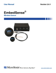
EmbedSense™ Wireless Sensor
Firmware Version 1.0 and higher
Software Version 1.0.1 and higher
Revised: 8 February 2008
Welcome
• Thank you for purchasing MicroStrain’s EmbedSense™ Wireless Sensor.
Software Installation
• Place the EmbedSense™ CD in your CD-ROM drive and follow the on-screen
instructions to install MicroStrain’s EmbedSense™ software.
Hardware Installation
• Connect one end of the BNC cable to the BNC connector on the Interrogation
Antenna.
• Connect the other end of the BNC cable to the BNC connector on the Reader
Assembly.
• Connect one end of the serial cable to the 9-pin RS-232 port on the Reader
Assembly.
• Connect the other end of the serial cable to a 9-pin RS-232 port on your host
computer.
• Connect the 5-pin DIN connector of the power supply to the 5-pin connector on
the Reader Assembly.
• Connect the power supply to the appropriate 100-240 VAC source.
• Observe that the green LED on the front panel of the Reader Assembly
illuminates indicating the unit is operating.
• Place your Node in close proximity to the Interrogation Antenna.
Software Operations
• Launch the EmbedSense™ software.
• The software Main screen will appear and the software will automatically scan the
host computer’s available serial ports and find the Reader Assembly.
• The port which is communicating with the Reader Assembly will be identified by
number in the Port Number box. See Figure 1.
• You may verify communications between the host computer and the Reader
Assembly by clicking the Ping (Port) button.
• Look for a successful ping message in the Console frame.
• You may reinitiate a scan for the Reader Assembly by clicking the Scan (Port)
button.
• Look for a successful scan message in the Console frame.
1
•
•
•
•
•
•
•
•
•
•
•
•
•
•
•
•
•
•
•
•
•
•
•
•
•
•
The next step is to verify communication between the Reader Assembly and the
Node.
Ensure that only one Node is lying on top of or underneath the Reader Assembly.
By default, an address of 16384 should be entered in the Node Address scroll box.
If not, enter that specific address.
Click the Ping (Node) button.
Look for a successful ping message in the Console frame. See Figure 2.
Note: Each Node has a unique address ranging between 1 and 65535. Look on the
Node label for the unique address applied at the factory. The exception is the
16384 ‘broadcast’ address; each Node will respond to its unique address and all
Nodes will respond to the broadcast address.
To determine the Node’s unique address, enter 50 in the EEPROM Location
scroll box; this is the location in the Node’s EEPROM map where its unique
address is maintained.
Click the Read button.
Look for a successful read message in the Console frame indicating what the
value in EEPROM 50 is and therefore the unique Node address. See Figure 3.
Note: When working with multiple nodes, the unique addresses should always be
used to insure data integrity.
Enter the address found in EEPROM 50 in the Node Address scroll box.
Click the Ping (Node) button.
Look for a successful ping message in the Console frame. See Figure 4.
An EmbedSense™ Node has 2 sensing channels.
Channel 1 is the internal temperature sensor and channel 2 is the differential input
circuit, designed to accommodate Wheatstone bridge sensors with 1000 ohm
resistors or greater.
The Node is supplied with a full Wheatstone bridge of 1000 ohm resistors for
evaluation.
Figure 5 shows the Calibration Coefficients required to scale the raw ‘bits’ from
the system into engineering units.
Enter 0.00457770 for the channel 1 (temperature sensor) Gain1.
Enter -50.0 for the channel 1 (temperature sensor) Offset 1.
Enter 0.001 for the channel 2 (differential input) Gain 2.
Enter 0.0 for the channel 2 (differential input) Offset 2.
Insure that the Node is in close proximity to the Interrogation Antenna
Click the Stream button.
Channels 1 (green trace) and 2 (red trace) will begin sampling and displaying on
the graph. See Figure 6.
The X-axis represents number of samples collected and the Y-axis represents
engineering units.
Note: Remember that two different engineering units are being displayed on the
same graph. The Y-axis auto-scales accordingly. In this case we are looking at
degrees C and millivolts.
2
•
•
After 30 seconds (as an example), remove the Node away from the Interrogation
Antenna. In a moment, the sampling will stop and a message box will appear
allowing you to Save/No Save the data collected.
If you click ‘Yes’ to save the data, a data file will automatically be created and
stored in the Data folder found in the application path of your EmbedSense™
software installation. The file will be named “Stream” and the timestamp will be
concatenated to the file name (example: [email protected]).
Congratulations!
You are off and running! Please read the EmbedSense™ User Manual to learn how to
successfully put your EmbedSense™ Wireless Sensor to work.
Figure 1
3
Figure 2
Figure 3
4
Figure 4
Figure 5
5
Figure 6
6


