1
IndustryPack Logic Interface Pin
Assignment
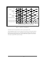
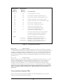
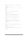
Figure 19 below gives the pin assignments for the IndustryPack Logic Interface connector on the
IP-Quadrature. Pins marked n/c below are defined by the specification, but not used on IPQuadrature. See also your User Manual for your IP Carrier board for more information.
GND
CLK
Reset*
D0 IDSel*
D1 n/c
D2 MEMSel*
D3 n/c
D4 INTSel*
D5 n/c
D6 IOSel*
D7 n/c
n/c
n/c
n/c
n/c
n/c
n/c
n/c
n/c
BS0*
n/c
BS1*
n/c
+5V
GND
GND
+5V
R/W*
4
5
6
7
8
9
10
11
A1
n/c
A2
n/c
A3
IntReq0*
A4
IntReq1*
A5
n/c
A6
Ack*
n/c
GND
1
2
3
27
28
29
30
31
32
33
34
35
36
12
13
14
15
16
17
18
19
20
21
22
23
37
38
39
40
41
42
43
44
45
46
47
48
24
25
Note 1: The no-connect (n/c) signals above are defined by the IndustryPack Logic Interface
Specification, but not used by this IP. See the Specification for more information.
Note 2: The layout of the pin numbers in this table corresponds to the physical placement of pins
on the IP connector. Thus this table may be used to easily locate the physical pin corresponding
to a desired signal. Pin 1 is marked with a square pad on the IndustryPack.
Figure 19
26
Logic Interface Pin Assignment
37
49
50