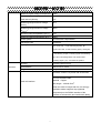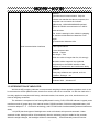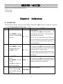
1
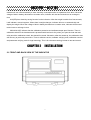
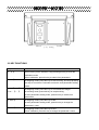
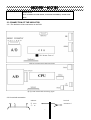
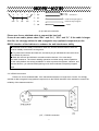
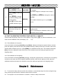
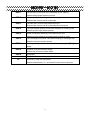
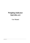
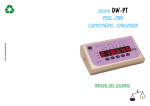
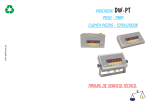
Digital Weighing Indicator
XK3190-A12(E)
User Manual
1
2008.10
2008.10 OC Version
XK3190
XK3190
A12(E)
A12(E)
12345346
CHAPTER 1 MAIN SPECIFICATIONS
………………….…….. …………..……….……....................-2-
1.1 TECHNICAL PARAMETERS OF INDICATOR
1.2 INTRODUCTION OF INDICATOR
CHAPTER 2 INSTALLATION
............... ............. ............. ............. ............................................. -5-
2.1 FRONT AND BACK VIEW OF INDICATOR
2.2 KEY FUNCTIONS
2.3 CONNECTION OF THE INDICATOR
CHAPTER 3 OPERATION
…………….… ……………………..…………………….....................……-8-
3.1 POWER ON AND AUTO ZERO
3.2 SEMI-AUTOMATIC ZERO-SETTING
3.3 TARE
3.4 COUNTING
3.5 ACCUMULATING
3.6 USER FUNCTION SETTING
3.7 SERIAL COMMUNICATION
CHAPTER 4 CALIBRATION …….……… ……………………...…..…………….... ...............................-12CHAPTER 5 MAINTENANCE ….. ………………...…………...………………….............. ……............ .-14CHAPTER 6 ERROR INDICATION
……………………….……………………… ……………………-15-
XK3190
XK3190
A12(E)
A12(E)
DEAR CUSTOMERS, PLEASE READ THE USER
GUIDE CAREFULLY BEFORE USING THE
INDICATOR!
178945A6B6 6 C8D36E95FDDF84D236
1.1 TECHNICAL PARAMETERS OF INDICATOR
Model name
XK3190 - A12
XK3190 - A12E
Self-indicating instrument
Indicator
Indicator type
Non-automatic weighing indicator
Software-embedded indicator
Platform scales
Application
1Commercial weighing and industrial weighing
1Instrument for not direct sales to the public
Accuracy Class
Class III
Value of the fractional error (pi)
0.5
Maximum number of verification scale
3000
intervals(nind)
Operating temperature range
02 402
Metrological
Initial zero-setting range
±10%Max
parameters
Semi-automatic zero-setting range
±2% Max
Zero-tracking range
±2% Max
Subtractive tare T-
Max
Scale divisions
1/2/5/10/20/50 optional
Relative humidity
385%RH
Storage and transportation
-25 552
temperature
Power supply
AC
230V / 50Hz
Battery
DC 6V/2.8Ah
Load cell excitation voltage (Uexc)
DC 5V
Minimum signal voltage for dead load
0mV
XK3190
XK3190
Maximum signal voltage for dead load
A12(E)
A12(E)
14mV
Minimum input-voltage per verification
scale interval (4Umin)
2µV
Measuring range minimum voltage
6mV
(UMRmin)
Measuring range maximum voltage
20mV
(UMRmax)
Minimum load cell impedance (RLmin)
875
Maximum load cell impedance (RLmax)
3505
Sense system
Six wires with compensation
A/D sample rate
10 times/s
Display
A12: 6 bits LCD 7 state indicating signals
6
A12E: 6 bits LED 8 state indicating lights
LED lights
In the following chapter, indicating signal and indicating
light will not be distinguished, both will be called
indicating signal
Structure
6 to indicate the position
Housing
Anti flaming plastic housing
Specifications
248mm*140mm*156mm
Weight
2.2kg
Six wires, connect 1-4 pieces 350 5 load cells
Load cell interface
Six-core shielded cable
Material Copper
Max length 100m/0.5mm2
When the cable is longer than 3m, it’s strongly
advised to add a magnetic loop (optional
component) on the RS232 interface of the
indicator to enhance the anti-interference ability
XK3190
XK3190
A12(E)
A12(E)
RS232C:
Unidirectional communication. Only the
indicator can transfer the data to computer, the
computer can not control the indicator.
Baud rate: 1200/2400/4800/9600 optional.
Data for RS232 communication is in ASCII
code as below:
The 1st bit is starting bit, the 10th bit is stopping
bit, and the middle 8 bits are data bits. Even
check.
Transmission distance<10m
Serial communication interfaces
Cable specifications:
2-core shielded cable
Material Copper
Max length 10m
When the cable is longer than 3m, it’s strongly
advised to add a magnetic loop (optional
component) on the RS232 interface of the
indicator to enhance the anti-interference ability
Software:
Third party softwares are optional, such as:
COMPort, Debuger…etc
Software environment:
Windows 2000 Windows XP
1.2 INTRODUCTION OF INDICATOR
XK3190-A12(E) weighing indicator is non-automatic weighing indicator applied to platform scale. It can
be connected to electric platform scale, electric floor scale, and can be connected 1-4 350 ohm load cells. It
is mainly applied to enterprise with factory, wholesale market, bus station, port, mine, warehouse etc, all
kinds of weighing occasions.
The indicator is composed of anti flaming ABS plastic housing, PCB, LED/LCD indicator, keypad, power
transformer and AC power plug, fuse, load cell socket, RS232 interface, 6V/4AH rechargeable battery. A/D
conversion adopts ∆
Σ conversion technology, and STC MCU with excellent stability and anti interference
ability.
A12(LCD) has three types of backlight user mode: still closed, still open and automatic. Under
automatic mode, backlight will be off automatically after the indicating weight is stable for few seconds.
When the weight changes, the backlight will be on automatically. It has automatic power off function.
XK3190
XK3190
A12(E)
A12(E)
Indicator will turn off automatically to save electricity consumption after no operations for a while. When the
voltage of built in battery decreases to a certain value, indicator will alert and remind user to recharge in
time.
A12(LED) has electricity saving function for the indication. After the weight is stable for a few seconds,
it will indicate a record segment; When there is weight changes, indicator will turn on automatically and
display the weight. When the voltage of built in battery decreases to a certain value, indicator will alert and
remind user to recharge in time.
XK3190-A12(E) indicator has the calibration protection and software tamper-proof function. There is
calibration switch on the hardware and is protected with lead seal. Only when you open the lead seal and
softly touch the calibration switch, the data will be saved. Otherwise, after the restart-up, the calibration data
will recovery to previously saved one. There is software version, software verifying code, calibration counter
and parameter verifying code for legal metrology. This is for relevant metrology bureau to test and control.
166 6 E6
6
2.1 FRONT AND BACK VIEW OF THE INDICATOR
1
1
XK3190
XK3190
A12(E)
A12(E)
1
234 1 56789AB1
2.2 KEY FUNCTIONS
Key
Function
#
When turning on the indicator, keep pressing this key to enter the
calibration mode
When calibration, press this key to switch from parameters
Func
At weighing mode, press this key to start counting; and keep pressing
this key for more than 5 seconds to enter the user parameters setting
mode
A12
A12E
Accum
*
At weighing mode, press this key to accumulate the weight
At counting mode, press this key for sample taking
At user parameters setting mode, press this key to switch from
parameters
Tare
At weighing mode, press this key to tare
At user parameters setting mode, press this key to change the
parameter’s value
Zero
At weighing mode, press this key to zero
When calibration, press this key to change the parameter’s value
XK3190
XK3190
ON/OFF
A12(E)
A12(E)
Power on/off
Note: A12E has no such button, on and off controlled by switch at the
back
2.3 CONNECTION OF THE INDICATOR
2.3.1 The definition of the connectors on the PCB
1 1 1 1 1 1 1 1 1 1 1 1 1 1 1 1 1 1 1 1 1 1 1 1 1 1 1 (2-2) A12 main board connecting figure
(2-3) A12E main board connecting figure
2.3.2 Load cell connection
1
indicator
EX-
S-
SH
EX+
S+
load cell
Excitation
XK3190
XK3190
A12(E)
A12(E)
S-
EX+
S+
IN-
IN+
EX-
Excitation
IN+
Load cell output signal
IN-
load cell output signal
SH
shield
(2-4) Load cell connection
1
Please use 6-core shielded cable to connect the load cell.
If uses 4-core cable, please short “EX+” and “S+” “EX-” and “S-”. If the cable is longer
than 3m, it’s strongly advised to add a magnetic loop (optional component) on the
RS232 interface of the indicator to enhance the anti-interference ability.
. Indicator must be reliably connected to load cell, and the shielded-cable of load cell
must be reliably connected to underground
. To protect the indicator and load cell, we cannot plug or withdraw the connector when
the indicator is power on.
. Both the load cell and indicator are static sensitive devices. You must adopt
anti-static measures. The electric welding operation and other strong electric operation
on the scale platform are strictly prohibited. In order to protect the operator, indicator, and
relevant devices, you should install lightning rod in the thunderstorm frequently happen
area
2.3.3 RS232 connection
Please use 2-core shielded cable. If the transmission distance is longer than 3 meter, it’s strongly
advised to add a magnetic loop (optional component) on the RS232 interface of the indicator to ensure the
reliability of the data transmission.
2-5
RS232 connection
XK3190
XK3190
A12(E)
A12(E)
6
178945A66 6 95A84D236
3.1 POWER ON AND AUTO ZERO
3.1.1 After turning on the switch on the back housing, keep pressing
ON/OFF key to turn on the indicator.
3.1.2 The indicator displays all sections, and all the indication signs first, then the display is as follow
(1) Model name:
(2) Version of the software: such as V
1.01
(3) Sections check: 111111-999999
If press [Func] before the indicator displaying the version of software, the indicator will display as below
(1) Model name:
(2) Version of the software: such as V
1.01
(3) Calibration times of the indicator: such as n 10
(4) Verification code of metrology parameters: such as C
1A5D
(5) Verification code of the software such as F 2B6C
(6) Sections check: 111111-999999
3.1.3 When power on, if the scale deviates from the zero point, but it’s still within auto zero range
(④10%Max), the indicator will zero automatically; if it is out of auto zero range, the indicator will
display Err 3 as warning, then show the weight.
Please warm the indicator up for 20 minutes before using to ensure the best performance
3.2 SEMI-AUTOMATIC ZERO-SETTING
3.2.1 At weighing mode, if there is any tolerance when unloaded, and the tolerance is within the semi-automatic
zero-setting range, press [Zero] to zero the scale.
If the tolerance is beyond the semi-automatic zero-setting range, the [Zero] key is invalid( Err 7 ), and you
need to recalibrate the scale.
3.2.2 Only when the stable indication sign is on, zero operation is valid.
3.3 TARE
At weighing mode, when displaying stable positive weight, and the weight is no more than F.S. , press
the[Tare] key to deduct the weight as tare. The indicator displays net weight as “0”, and the “Net” indication
sign is on. When the displaying weight is negative or zero, pressing [Tare] key can clear the saved tare
weight, and get back to gross weight displaying mode. The “Net” indication sign will be off.
XK3190
XK3190
A12(E)
A12(E)
3.4 COUNTING
At weighing mode, press [Func] to enter the counting mode. Indicator displays “count”, and we can load
the scale. When stable indication sign is on, press [*] key, indicator displays “C00000”, then press [Tare] to
move the small indication triangle directedly, the number corresponded with the small triangle means the
sample quantity, and this number will increase by one when press [Zero] key. After inputting the sample
quantity, press [*] key to start the counting. The counting indication sign will be on.
At counting mode, press [Func] key to return to weighing mode.
Note:
When “count” is displayed after we pressing [Func] key at the weighing mode, press [*] twice to enter
counting mode directly. Indicator will count according to last time sampling result.
In this process, if the Err 4 appears, it means sampling failed, the indicator will keep the result of last
sampling.
3.5 ACCUMULATING
At weighing mode, when the displaying value is positive and stable, press [*] key to accumulate the
present weight. Press [*] key again, it gets back to weighing mode. The next accumulating operation must
be performed after the weight return to zero. When the scale displaying zero, press [*] to display the
accumulated weight.
At accumulating mode, press [Func] key to clear the accumulated weight in Memory.
3.6 USER FUNCTIONS SETTING
At weighing mode, keeping pressing [Func] for more than 5 seconds, it enters user functions setting
mode (mode P). There are 9 parameters. Press [*] to change the parameter, and press [Tare] to change
the value. After setting the parameters, press [Func] to save.
Note: The parameters P6, P7, P8, and P9 are metrological related. We need to press the calibration switch
on the back housing to save the settings.
Parameters are as below:
1 P1
2 P2
3 P3
x
Automatically power off
(Default setting:1)
X=1:
Close this function
X=2:
X=3
Auto power off 10 minutes after last operation
Auto power off 20 minutes after last operation
X=4
Auto power off 30 minutes after last operation
x
Baud rate setting
X=1:
9600
X=2:
4800
X=3:
2400
X=4:
x
1200
RS232 output content
(Default setting:4)
(Default setting:1)
XK3190
XK3190
X=1:
4 P4
5 P5
6 P6
7 P7
8 P8
9 P9
X=2:
x
A12(E)
A12(E)
Net weight output
Gross weight output
RS232 output mode
X=1:
No transmission (RS232 stop)
X=2:
Continuous transmission
X=3:
x
Continuous transmission only when stable
Backlight mode
(Default setting:2)
X=1:
No backlight
X=2:
Automatic backlight
X=3:
Constant backlight
x
Zero-tracking range
X=1:
0.5e
X=2:
No zero tracking
x
Digital filtering intensity
X=1:
High
X=2:
Medium
X=3:
x
Low
Stabling speed
X=1:
Fast
X=2:
Medium
X=3:
x
(Default setting:1)
Slow
Stable range
X=1:
Wide
X=2:
Medium
X=3:
Narrow
(Default setting:1)
(Default setting:2)
(Default setting:2)
(Default setting:2)
3.7 SERIAL COMMUNICATION (RS232)
Make sure that communication interfaces are correctly connected. If there is anything wrong with the
connection, damage may happen to output port of the indicator, input port of the computer, and even
other peripherals may get involved.
Necessary computer technology and programming skills are required for computer communication,
which should be participated and instructed by professionals. Non-professional staff is supposed not to
be involved in this regard.
Detailed connection instruction kindly check the 2.3.3 on page 8
Data for RS232 communication is in ASCII code. The format is as below:
The 1st bit is starting bit, the 10th bit is stopping bit, and the middle 8 bits are data bits. Even check.
XK3190
XK3190
A12(E)
A12(E)
Communication mode as follows:
(1)At normal weighing mode, every group of data consists of 15 bytes as below:
1st byte: ‘W’
2nd byte: ‘G’ (when the weighing result is gross weight)
‘N’ (when the weighing result is net weight)
rd
th
3 -9 byte: Weighing result including the decimal point
When there is no decimal point, the 9th bit is blank (0x20)
When the weight is negative, the 3rd bit is the negative sign (0x2d)
th
10 and 11th byte: Unit k g (0x6B, 0x67)
12th byte: the 4 high bits of checksum
13th byte: the 4 low bits of checksum
14th byte: 0x0d
15th byte: 0x0a
Note:
The checksum is from 1st byte to 11th byte
If 4 high bits or 4 low bits of checksum is 9, add 30h and transmit in ASCII code.
For example, if the 4 high bits checksum is 6, then we add 30h, and transmit 36h in ASCII code “6”.
If the checksum>9, then add 37h, and transmit in ASCII code. For example, if the 4 high bits checksum is B,
then we add 37h, and transmit 42h in ASCII code “B”.
For example, if the weight is 4.139 Kg, the transmission format is as follow:
ASCII: W G 0 0 4 . 1 3 9 k g 3 D
Hex: 57 47 30 30 34 2E 31 33 39 6B 67 33 44 0D 0A
(2)When the scale is overloaded (G.W>Max+9e), the indicator will send “
st
OL23” in 15 bytes as follow:
th
1 to 9 byte: Blank (0x20)
10th byte: ‘O’ (0x4f)
11th byte: ‘L’ (0x4c)
12th byte: the 4 high bits of checksum (0x32)
13th byte: the 4 low bits of checksum (0x33)
14th byte: 0x0d
15th byte: 0x0a
(3)When the weight is less than -20d, the indictor will send “
st
th
1 to 9 byte: Blank (0x20)
10th byte: ‘L’ (0x4c)
11th byte: ‘O’ (0x4f)
12th byte: the 4 high bits of checksum (0x32)
L023” in 15 bytes as follow:
XK3190
XK3190
A12(E)
A12(E)
13th byte: the 4 low bits of checksum (0x33)
14th byte: 0x0d
15th byte: 0x0a
6
178945A66 6 18D A84D236
4.1 CALIBRATION
Connect load cell properly, then turn on the indicator, keep pressing [#] key while it’s initializing, it will enter
the calibration mode, and display
STEP
OPERATION
d
X
.
DISPLAY
NOTES
Division setting.
For example: Press [#] when displayed d
Press [TARE] to change
1
the division, and press [#]
to confirm
5 ,
then the division is set to be“5”, and the indicator
[d
X
]
enters decimal point setting.
Note: The 10, 20, 50 divisions are only valid when
there is no decimal point. When there is a decimal
point, the 10, 20, 50 divisions will be turned to 1, 2,
and 5 automatically.
Decimal point setting
2
Press [TARE] to change
For example: Press [#] when displayed P 0.000 ,
the decimal point, and
then the decimal point is set to be “0.000”, and the
press[#] to confirm
[P
X
]
indicator enters full capacity setting
Note: When there is a decimal point, division 10,
20, 50 are invalid, and will be turned to 1, 2, and 5
automatically.
Press [TARE] to select the
Full capacity setting
digit bit;
For example: Press [#] when displayed 025000 ,
Press [ZERO] to change
3
[FULL ]
the value;
then the full capacity is set to be “25000”, and the
indicator enters zero point calibration
Press [#] for confirm the
input of full capacity
Make sure there is no load
4
on scale, and press [#]
when the stable indication
sign is on
Zero point calibration
[nOLOAD]
XK3190
XK3190
A12(E)
A12(E)
Add full capacity load,
Calibrate the full capacity
press [TARE] to continue [AdLOAD]
For example:
Load 25000 weight on scale(as we set in step 3)
Press [TARE] to select the
5
digit bit;
Use [TARE] and [ZERO] to change the value to
Press [ZERO] to change
be 25000.
the value accordingly with
[025000]
the full capacity;
Press [#] to confirm when
When stable indication sign is on, press [#] to
confirm.
the stable indication sign is
on
It saves the calibration parameter and back to the
Press the calibration switch
6
at the back housing of the
weighing mode.
[ End]
Note: if no pressing the calibration switch, all the
indicator.
parameters won’t be saved.
4.2 FAST CALIBRATION FOR ZERO POINT AND FULL CAPACITY
Connect load cell properly, then turn on the indicator, keep pressing [ # ] key while its initialization, it will
enter into the calibration mode, and display
d
X
.
4.2.1 Fast calibration of zero point:
At any time before it showing [nOLOAD], press [FUNC]. Indicator will keep the original division, decimal
point, full capacity, and enter the zero point calibration directly. Making sure there is no load on the scale,
and the stable indication sign is on, press [ZERO] to re-calibrate the zero point. The indicator will display
[End]. Press the calibration switch at the back of the indicator to save the setting and get back to the
weighing status.
4.2.2 Fast calibration of full capacity:
At any time before it showing [AdLOAD], press [*]. It keeps the original division, decimal point, full capacity,
zero point, and enters into the full capacity calibration directly. After the full capacity is reset, press the
calibration switch at the back of the indicator to save the setting and get back to the weighing status.
6
6
178945A6!6 6 C8D345383F56
6
5.1 To ensure the clarity and service life of the indicator, it must be kept away from direct sunlight during
using, and the ground where the indicator stands must be smooth.
5.2 It is improper to use this indicator in a dustful or vibrant or damp environment.
XK3190
XK3190
A12(E)
A12(E)
5.3 The load cell and indicator need good connection. System must have a good ground connection, and
kept away from strong electric field, strong magnetic field. The load cell and indicator must be kept away
from strong corrosive substances and inflammable& explosive materials.
7
Do not use it where inflammable gases or steams exist. Don’t use it for canning system of compressive
container.
7
In the area where lightning and thunder happen frequently, reliable lightning arrester should be installed
to ensure the personal safety and to prevent any damage to the indicator and relative equipment caused by
lightning stroke.
7 The load cell and indicator are both static sensitive equipments, so anti-static measures must be taken
during the use. It is strictly invalid to carry out welding operation or other operations with high current on the
weighing platform. In the stormy season, lightening prevention measures must be taken reliably to prevent
any damage to load cell and indicator caused by lightening stroke, and to guarantee the personal security of
operators and safe running of weighing devices and relative equipments.
5.4 Strong solvents such as benzyl and nitro oils are forbidden for cleaning the housing
5.5 Don’t inject any liquid or other conductive particles so as to avoid any damage of indicator and electric
shock
5.6 Before plugging in or out of the connecting line between indicator and external equipment, the power
of both indicator and equipment should be cut off
5.7 Advice of the company: our company is responsible for the indicator quality, but not responsible for the
problems of the system where the indicator locates. Your attention is required when making purchase.
5.8 Please use the indicator outward interfaces strictly as per the operating instruction manual. Do not
change the connection at random. If failure occurs in the using process, draw the plug immediately, and
send it for professional factory for reparation. Non professional balance manufacturers are not supposed to
do the repairing to avoid any worse damage. It is not allowed to open the indicator at will, or else, repairing
will be refused.
5.9 If non artificial defects and failures happen after normal use within one year after the sale date, the
users can mail the product and guarantee repair card ( with correct code) to the appointed reparation station
or supplier. The manufacturer guarantees the life-time maintenance for the indicator.
6
178945A6"6 6 AA2A63#DF84D236
XK3190
XK3190
ERR 1
A12(E)
A12(E)
The AD value is too small when calibrating the full capacity
Please change proper capacity load cell
ERR 2
The zero point is out of range when calibrating the zero point
Please make sure no load is on the scale
ERR 3
The zero point is out of range when turning on
Please make sure no load is on the scale when turning on
ERR 4
The input sample quantity is zero when sampling in counting mode
Please input the right sample quantity
ERR 5
When full capacity calibrating, the weight input is zero
Please input the weight in accordance with the load on scale
ERR 6
The unit weight is less than 0.25e when sampling in counting mode
Please re-input the sample quantity
ERR 7
The weight is beyond the semi-automatic zero-setting range, the [Zero] key is
invalid.
ERR 8
Overflow of the accumulated weight
Please clear the accumulated weight
bAt-lo
Low power
Lo
The G.W. is less than -20e
oL
Overload, or load cell malfunction
Please recalibrate the F.S., and check the connection of load cell