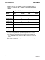
1
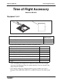
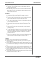
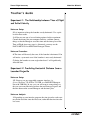
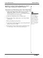
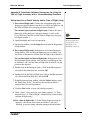
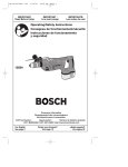
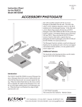
Instruction Manual Manual No. 012-05088D Time of Flight Accessory Model No. ME-6810 RY RANGE HER SHORT LAUNC CTILE CAUTION! LOOK DO NOT BARREL! DOWN PROJE -O E TIM L UT NA TP SIG +5V OU GND L ITA DIG ME-6800 H IG L F-F E CC TA WEAR SAFETY GLASSES IN USE. WHEN 10 68 ME O SS N UTIO TIC CASE PLASS ONLY! U BALL Time of Flight Accessory Model No. ME-6810 Table of Contents Equipment List........................................................... 3 Equipment Requirements for Suggested Experiments...................................................................4 Introduction ............................................................. 5 Setup Options ........................................................... 5 Set up the Time of Flight Accessory with a Photogate Timer .......................................................6 a) Setup for a Time of Flight Study (with Timer)........................................................................6 b) Setup for an Initial Speed and Time of Flight Study (with Timer) .........................................6 Set up the Time of Flight Accessory with a Computer Interface...................................................7 a) Setup for a Time of Flight Study (with Interface)...................................................................7 b) Setup for an Initial Speed and Time of Flight Study (with Interface).....................................8 Experiments ......................................................... 9-14 Experiment 1: The Relationship between Time of Flight and Initial Velocity........................ 9-10 Experiment 2: Predicting the Horizontal Distance Traveled from a Launched Projectile..... 11-13 Experiment 3: Horizontal Velocity of a Projectile................................................................. 14-15 Teacher’s Guide ........................................................16 Appendix A: DataStudio® Software Instructions for Using the Time of Flight Accessory with a PASPORTTM Interface .................. 18 Appendix B: DataStudio Software Instructions for Using the Time of Flight Accessory with a ScienceWorkshop Interface ........... 19-20 Appendix C: ScienceWorkshop® Software Instructions for Using the Time of Flight Accessory with a Computer Interface........... 21-22 Appendix D: Technical Support ....................................... 23 Appendix E: Copyright, Warranty, and Equipment Return .......... 24 2 ® Model No. ME-6810 Time of Flight Accessory Time of Flight Accessory Model No. ME-6810 Equipment List 1 2 Y OR SS 10 CE C -68 ME HT A RANGE SHORT LAUNCHER WEAR SAFETY GLASSES IN USE. WHEN ME-6800 CAUTION! LOOK DO NOT BARREL! DOWN ITAL DIG L UT NA TP SIG +5V OU GND PROJECTILE -F OF E- TIM LIG TION Y! CAU PLASTIC USEBALLS ONL Included Equipment Replacement Model Number* 1. Time of Flight Accessory ME-6810 2. Ziplock bag 735-016 *Use Replacement Model Numbers to expedite replacement orders. Equipment Required 1. Projectile Launcher 2. Photogate Mounting Bracket 3. Photogate 4. Data acquisition software** 5. Interface (ScienceWorkshop® or PASPORT™) or Timer** 6. Phone jack extender cable* 7. Ruler ME-6800 or ME-6801 ME-6821 ME-9204A or ME-9498 CI-6870C CI-6450 or CI-7599 or PS-2123 with PS-2100 PI-8117 NA * Note: The phone jack extender may be required to connect the Time-of-Flight Accessory to the Photogate Timer or computer interface if you are using the Long Range Projectile Launcher. ** If an interface and/or data collection software are not available, you can use a Photogate Timer (ME-9206A, ME-9215A, or ME-8930) instead. See table on page 4. ® 3 Time of Flight Accessory Model No. ME-6810 Equipment needs may vary, depending on the types of experiments you plan to perform. Use the following table as a guideline for determining what equipment you need. Time of Flight Experiments Initial Speed Experiments Equipment Required Photogate Timer Computer Interface* Photogate Timer Computer Interface* Time of Flight Accessory x x x x Projectile Launcher x x x x Photogate Timer x Photogate Bracket x x x x Photogate x (1)† x (1)† x (1-2)†† x(1-2)†† Interface Ruler x x DataStudio Phone jack extender cable † x x x x x x x x One photogate is required for measuring only the initial speed; two photogates are required for measuring both initial speed and time of flight in the same experiment. †† The computer interface must be either a PASCO ScienceWorkshop interface (CI-6450 or CI7599) or a PASPORT Photogate Port (PS-2123) with USB Link (PS-2100) and USB-compatible computer. Note: Most experiments require either a computer interface or a Photogate Timer. See “Setup Options” on pages 6-9 of this manual. 4 ® Model No. ME-6810 Time of Flight Accessory Introduction The PASCO ME-6810 Time-of-Flight Accessory is for use with PASCO Projectile Launchers. It consists of a piezo-electric speaker circuit mounted on a 20 x 20 centimeter plastic plate. The plate has a signal cable with a 6 mm (1/4”) stereo phone plug. When a ball hits the plate, the speaker circuit generates a Photogate-like pulse. The cable sends the signal to a timer. The Time-of-Flight Accessory was designed for use with a PASCO Photogate Timer or a PASCO computer interface (such as the ScienceWorkshop Interface® or a PASPORT Photogate Port with USB link) for Macintosh® or Windows® computers. Setup Options The Time of Flight Accessory can be used with a Photogate Timer or a computer interface for time of flight or initial speed studies. If using a computer interface, you will also need data collection software, such as DataStudio. If you plan to measure initial speed and time of flight in the same experiment, you will need two photogates for the setup. Time of Flight Study - Setup Using One Photogate Projectile Launcher CAUTION: For projectile-based studies with balls, use only 25 mm plastic balls or 16 mm steel balls. Using 25 mm steel balls will damage the unit. Photogate WE SA AR GL FE WH AS TY EN SE IN S US E. ME -68 00 DODO CAU WN NO TIO T BA LOON! PR RR EL!K OJ ECSH TI ORT LE RA LA NG UNE CH ER Plug to timer or interface Time-of-Flight Accessory Time of Flight and Initial Speed Study - Setup Using Two 2 Photogates REL K ! Plug to timer or interface WE SA AR GL FE WH AS TY EN SE IN S US E. ME -68 00 PR OJ DO CAU DOW NOT TIO N BARLOON! 10 cm ECSH TI ORT LE RA LA NG UNE CH ER Projectile Launcher Time-of-Flight Accessory Figure 1 ® 5 Time of Flight Accessory Model No. ME-6810 Setup the Time of Flight Accessory with a Photogate Timer a) Setup for a Time of Flight Study (with Timer) Equipment Requirements: See page 4 of this manual. 1. Remove the Photogate Head from the support rod of the Photogate Timer. 2. Put the Photogate Mounting Bracket onto the Projectile Launcher. Mount the Photogate Head at the front of the Launcher. Photogate Head Projectile Launcher To Photogate Timer Photogate Mounting Bracket Figure 2: Attaching the Photogate Mounting Bracket 3. Connect the Time-ofFlight accessory stereo phone plug into the side of the Photogate Timer. DIGITAL OUTPUT GND SIGNAL Connect stereo phone plug here. 4. Set the Photogate Timer to PULSE mode Figure 3: Photogate Timer (side view) to measure the time of flight of the projectile from the launcher to the pad. +5V b) Setup for an Initial Speed and Time of Flight Study (with Timer) Equipment requirements: See page 4 of this manual. 1. Remove the Photogate Head from the support rod of the Photogate Timer. 2. Put the Photogate Mounting Bracket onto the Projectile Launcher. Mount the Photogate Head at the closest position on the front of the Projectile Launcher. Mount the second photogate at the farthest position on the mounting bracket. 3. Measure the distance between the photogates. You will use this distance and the measured time between the photogates to calculate the initial speed of the projectile (ball). 6 ® Model No. ME-6810 Time of Flight Accessory 4. Connect the stereo plug of the first photogate into the Timer. Set the Photogate Timer to PULSE mode to measure the time of the projectile from the first photogate to the second photogate. 5. Connect the stereo plug of the Time of Flight Accessory into a second timer or a Smart Timer (ME-8930). (Note: If you do not wish to measure time of flight, skip this step.) Set up the Time of Flight Accessory with a Computer Interface You can setup the Time of Flight Accessory for use with a computer interface and either DataStudio™ or ScienceWorkshop® software. a) Set up for a Time of Flight Study (with interface) Equipment Required: 1 Photogate with bracket, 1 ScienceWorkshop® interface (CI-6400 or CI-6450) OR 1 PASPORT Photogate Port (PS2123) with USB Link (PS-2100) and USB-compatible computer, 1 Time of Flight Accessory, 1 Projectile Launcher, DataStudio software 1. Put the Photogate Mounting Bracket on to the Projectile Launcher and mount the photogate at the front of the launcher. Projectile Launcher Photogate Head To computer 2. For ScienceWorkshop interface Photogate Mounting Bracket interfaces: Insert the Photogate’s stereo Figure 4: Mounting the Photogate on the Launcher phone plug into Digital Channel 1 and the Time-of-Flight Accessory stereo phone plug into digital channel 2 on the interface. OR For PASPORT interfaces: Insert the stereo plug of the photogate into Port 1 on the PASPORT Photogate Port and the stereo plug for the Time of Flight Accessory into Port 2 on the PASPORT Photogate Port. Connect the Photogate Port to a USB link and USB port on your computer. 3. Use the computer program that came with your interface to measure the time of flight of the projectile from the launcher to the ® 7 Time of Flight Accessory Model No. ME-6810 pad. (For information about using computer software with the interface, see Appendices A-C of this manual). b) Set up for an Initial Speed and Time of Flight Study (with interface) Equipment Required: 2 Photogates with brackets, 1 ScienceWorkshop® interface (CI-6400 or CI-6450) OR 2 PASPORT Photogate Port (PS-2123) with 2 USB Links (PS-2100) and USBcompatible computer, 1 Time of Flight Accessory, 1 Projectile Launcher, DataStudio software 1. Put the Photogate Mounting Bracket onto the Projectile Launcher. Mount one Photogate at the closest position to the front of the launcher. Mount the second photogate at the farthest position on the bracket. Projectile Launcher Photogates To computer interface Photogate Mounting Bracket Figure 5: Mounting the Photogates on the Launcher 2. For ScienceWorkshop interfaces: Connect the stereo phone plug from the Photogate that is closest to the projectile launcher into digital channel 1, the stereo phone plug of the second photogate into digital channel 2, and the stereo plug of the Time-of-Flight accessory into digital channel 3 on the interface. For PASPORT interfaces: Insert the stereo plug of the photogate into Port 1 on the PASPORT Photogate Port, the stereo plug of the second photogate into Port 2 on the Photogate port, and the Time of Flight Accessory into either Port 1 or Port 2 on a second Photogate Port. Connect each Photogate Port to a USB link and USB port on your computer. 3. Use the computer program that came with your interface to measure the initial speed and overall time of flight of the projectile from the launcher to the pad (For more information about using a computer program to time the projectile, see Appendices A-C of this manual.) 8 ® Model No. ME-6810 Time of Flight Accessory Experiment 1: The Relationship between Time of Flight and Initial Velocity Equipment required Computer interface (CI-6450 or CI-7599 or PS-2123 with PS-2100)* Projectile Launcher and ball (ME-6800 or ME-6801) Time-of-Flight Accessory (ME-6810) Photogate Mounting Bracket (ME-6821) Phone Jack Extender Cable (PI-8117) Photogate Head (ME-9498) *If a computer interface is not available, use a Photogate Timer (ME-8930). Purpose: The purpose of this experiment is to show that the time of flight of a ball launched horizontally off a table does not change as the initial velocity is varied. Theory: A ball is launched horizontally off a table from a height h and has no initial velocity in the vertical direction. Hence, the ball takes the same amount of time to reach the ground as a ball that drops from rest at the same height. The equation 1 2 h = --- gt 2 gives the time of flight, which is independent of the initial velocity. Therefore, 1. Clamp the Projectile Launcher to one end of a sturdy table with the launcher aimed away from the table. 2. Adjust the angle of the Projectile Launcher to zero degrees so the ball will launch horizontally. t = h 2 --- . g CAUTION! DO NOT LOOK DOWN BARREL! WEAR SAFETY GLASSES WHEN IN USE. ME-6800 SHORT RANGE PROJECTILE LAUNCHER Figure 1.1: Experiment Setup 3. Attach the Photogate Mounting Bracket to the Launcher and attach the Photogate to the bracket. Plug the Photogates into the computer interface. ® 9 Time of Flight Accessory Model No. ME-6810 4. Connect the Time-of-Flight Accessory into the computer interface using the extender cable. 5. Run the timing program and set it to measure the time between the blocking of two photogates (one Photogate and the timer plate of the Time-of-Flight Accessory). Procedure: 1. Put the plastic ball into the Projectile Launcher and cock it to the short range position. 2. Test fire the ball to determine where to place the timer plate on the floor. Put the timer plate on the floor where the ball hits. 3. Shoot the ball on the short range position and record the time of flight in Table 1.1. 4. Repeat steps 1-3 for the medium range and long range. Are the times the same? 5. Set the angle of the launcher to 300 and shoot it again on the long range setting. Move the timer plate to the new landing position so the ball will hit the plate. Shoot again and record the time of flight in Table 1.1. Is this time the same as the others? Table 1.1: Results Range Time Short Medium Long Long at 300 10 ® Model No. ME-6810 Time of Flight Accessory Experiment 2: Predicting the Horizontal Distance Traveled from a Launched Projectile Equipment required: Computer interface* (CI-6450 or CI7599 or PS-2123 with PS-2100) Time of Flight Accessory (ME-6810) DataStudio software (CI-6870)* Cable (PI-8117) Projectile Launcher and ball (ME6800 or ME-6801) Photogate Mounting Bracket (ME6821) Photogate Heads (ME-9498) Measuring tape or stick Plum bob (SE-8728) White and carbon paper *If a computer interface is not available, use a Photogate Timer (ME-8930). Purpose: The purpose of this experiment is to use the time of flight and the initial velocity to predict the horizontal distance traveled by a ball shot off a table at an angle. Theory: A ball is launched off a table from a height h at an angle θ above the horizontal. The horizontal distance, x, traveled by the ball is given by x = v0 cos θ t where v 0 is the initial velocity of the ball and t is the time of flight. 2. Adjust the angle of the Projectile Launcher to any desired angle. Record the angle in Table 2.1. DO CAU DOW NOT TION N BARLOO ! REL K ! ECSH TILORT E RA LA NG UNE CH PR OJ ME -68 00 . WE SAF AR GLA ETY WH SSE EN IN S USE 1. Clamp the Projectile Launcher to one end of a sturdy table with the launcher aimed away from the table. ER Setup: Figure 2.1: Experiment Setup 3. Attach the Photogate Mounting Bracket to the Launcher and connect the Photogates to the computer interface. ® 11 Time of Flight Accessory Model No. ME-6810 4. Connect the Time-of-Flight Accessory to the computer interface using the extender cable. 5. Run the timing program and set it to measure the time between the three successive signals (two Photogates and the timer plate of the Time-of-Flight Accessory). Procedure: 1. Put the plastic ball into the Projectile Launcher and cock it. 2. Test fire the ball to determine where to place the timer plate on the floor. Put the timer plate on the floor where the ball hit. 3. Tape a piece of white paper and a piece of carbon paper to the plate to record where the ball lands. 4. Shoot the ball and record the times between Photogates in Table 2.1. 5. Shoot the ball 9 more times to determine the average horizontal distance traveled. 6. Use the Plumb Bob to find the place on the floor directly below the muzzle of the launcher. Measure the horizontal distance along the floor to the leading edge of the paper on the plate. Record this distance in Table 2.1. 7. Remove the carbon paper and measure from the leading edge of the paper to each of the dots on the paper. Record in Table 2.1. Analysis: 1. Find the average of the ten distances and record in Table 2.1. 2. Add the distance to the leading edge of the paper to the average and record in Table 2.2. 3. Calculate the time of flight by adding the time between photogates 1 and 2 and the time between photogate 2 and the timer plate. Record in Table 2.2. 4. Calculate the initial velocity using the time between photogates 1 and 2 and the distance between the photogates (10 cm). Record in Table 2.2. 5. Calculate the horizontal distance using the time, initial velocity, and angle and record in Table 2.2. 6. Calculate the percent difference between the measured distance and the calculated distance. Record in Table 2.2. 12 ® Model No. ME-6810 Time of Flight Accessory Results Angle_________________ Time between photogates___________ Time between second photogate and timer plate______________ Distance to paper_____________________ Table 2.1: Results Distance 1 2 3 4 5 6 7 8 9 10 Average Table 2.2: Results Total distance Time of flight Initial velocity Calculated distance Percent (%) difference ® 13 Time of Flight Accessory Model No. ME-6810 Experiment 3: Horizontal Velocity of a Projectile Equipment required: Computer interface (CI-6450 or CI7599 or PS-2123 with PS-2100)* Time of Flight Accessory (ME-6810) Projectile Launcher and ball (ME6800 or ME-6801) Phone Jack Extender Cable (PI-8117) DataStudio software (CI-6870C) Photogate Mounting Bracket (ME-6821) Photogate Head (ME-9498) Measuring tape or stick Plum Bob (SE-8728) White paper Carbon paper Vertical target board *If a computer interface is not available, use a Photogate Timer (ME-8930). Purpose: The purpose is to show that the horizontal velocity of a projectile is constant throughout its flight. Theory: For projectile motion, the horizontal and vertical motions are separate. In the vertical direction, the projectile accelerates downward as gravity pulls on it. But in the horizontal direction, there is no acceleration and the component of the velocity in the horizontal direction is constant (neglecting friction). The horizontal velocity can be found by measuring the horizontal distance and the time of flight (i.e. Vx = x--t- ). Setup: 1. Clamp the Projectile Launcher to one end of a sturdy table with the launcher aimed along the length of the table. 2. Adjust the angle of the Projectile Launcher to any desired angle. CAUTION! LOOK DO NOT BARREL! DOWN RANGE CHER SHORTE LAUN 0 ME-680 PROJ ECTIL WEAR SAFETY S GLASSEIN USE. WHEN 0.5 m at least 2 m Figure 3.1: Experiment Setup 3. Attach the Photogate Mounting Bracket to the launcher and attach the Photogate to the 14 ® Model No. ME-6810 Time of Flight Accessory bracket. Plug the Photogate into Channel 1 on the computer interface. 4. Connect the Time-of-Flight Accessory to the computer interface. Use the extender cable if necessary. 5. Run the timing program and set it to measure the time between blocking of two Photogates (one Photogate and the timer plate of the Time-of-Flight Accessory). 6. Set up the vertical target board about 0.5 m in front of the Projectile Launcher. Use the Plumb Bob to aid with the measurement of the exact distance between the muzzle of the launcher and the timer plate. Record the distance in Table 3.1. Procedure: 1. Load and cock the launcher to the long range position. 2. Fire a test shot to see where the ball hits the vertical target. Hold the timer plate against the vertical board at the place where the ball hit. 3. Shoot the ball again and record the time of flight in Table 3.1. 4. Move the vertical target to 1 m, 1.5 m, and 2 m in succession, finding the time of flight for each position and recording in Table 3.1. Analysis 1. Calculate the horizontal velocity for each position. Is the velocity constant? Table 3.1 : Data and Results Distance ® Time Horizontal Velocity 15 Time of Flight Accessory Model No. ME-6810 Teacher’s Guide Experiment 1: The Relationship between Time of Flight and Initial Velocity Notes on Setup: 2. It is important to keep the launcher exactly horizontal. Use a spirit level for best results. 3, 4. You may use one of several timing options for this experiment. Consult the manual for your computer interface, and then connect things so that the Photogate starts the timer and the timer plate of the Time-of-Flight Accessory stops it. Alternately, you may use the PASCO ME-9215A or ME-9206A Photogate Timers. Notes on Procedure: 4. The times will be nearly the same, if the launcher is horizontal. You will notice a systematic error if the launcher is not exactly horizontal. 5. Setting the launcher to some angle other than 0° will significantly affect the time. Experiment 2: Predicting Horizontal Distance from a Launched Projectile Notes on Setup: 3-5. You may use any compatible computer interface (i.e. ScienceWorkshop 750 SCSI or 750 USB, or a PASPORT Photogate Port with USB link). In any case, you will want to arrange things so that you can record the times between the two Photogate signals and the time between the second Photogate and the timer plate. Notes on Analysis: 3. Depending on your interface program, the time given for each event may be the total time since the first event, rather than the time since the last event. 16 ® Model No. ME-6810 Time of Flight Accessory 4. The initial velocity should be close to that measured in other experiments (See manual experiments 1 and 2, for example.) 6. The difference should be less than 5%. Experiment 3: Horizontal Velocity of a Projectile Notes on Setup: 3-5. If necessary, consult your interface manual. The system should be set up in such a way that the computer measures the time between the Photogate and the timer plate. 6. The “Vertical Target Board” can be any convenient moveable vertical object. Notes on Analysis: The velocity is not constant. It is nearly constant, but this equipment is sensitive enough to observe the change in velocity due to air resistance. This air resistance will result in your measured velocity being slightly lower at longer distances. You may ignore this effect if you wish, or you may want the students to further investigate the air resistance. ® 17 Time of Flight Accessory Model No. ME-6810 Appendix A: DataStudio Software Instructions for Using the Time of Flight Accessory with a PASPORT Interface Instructions for an Initial Velocity and/or Time of Flight Study 1. Connect the photogate and time of flight accessory stereo plugs to the Photogate Ports. [Note: You will need 1-2 photogates and 1-2 PASPORT Photogate Ports (PS-2123). See the PASPORT interface Note: To change measetup instructions on page 7 of this manual.] 2. Connect the each Photogate Port to a USB link or hub. 3. When the Choose Timer window appears, select "Time in Flight" and click OK. 4. Measure the photogate spacing (meters). 5. At the Change Variable Values prompt, accept or change the default photogate spacing and click OK. surement parameters, click on the Setup button to open the PASPORT Setup window. Scroll to the Time of Flight options and check to add options or uncheck to remove them. For more information, see the DataStudio online help. 6. Initial Velocity and time of flight parameters automatically appear in a Table display. You are ready to begin collecting data. 18 ® Model No. ME-6810 Time of Flight Accessory Appendix B: DataStudio Software Instructions for Using the Time of Flight Accessory with a ScienceWorkshop Interface Instructions for an Initial Velocity and/or Time of Flight Study 1. For a time of flight study: Connect the stereo phone plug of the photogate to digital channel 1 on the ScienceWorkshop interface and the Time-of-Flight Accessory plug into digital channel 2. For an initial speed and time of flight study: Connect the stereo phone plug of the photogates to digital channels 1 and 2 on the ScienceWorkshop interface and the Time-of-Flight Accessory plug into digital channel 3. 2. Open DataStudio and create an experiment. 3. On the main toolbar, click the Setup button to open the Experiment Setup window. For more information about using photogates or timing devices with DataStudio, see the DataStudio online help. 4. For a time of flight study: In the Sensors list of the Experiment Setup window, click and drag the Photogate icon to channel 1 on the picture of the interface and the Time of Flight icon to channel 2. For an initial speed and time of flight study: In the Sensors list of the Experiment Setup window, click and drag each Photogate icon to channels 1 and 2 and the Time of Flight icon to channel 3 on the picture of the interface. 5. Double click on the Photogate icon(s), click on the Measurement tab click to check the State box, and click OK. 6. Double click on the Time of Flight icon, click on the Measurement tab, click to check the State box, and click OK. 7. In the Experiment Setup window, click the Timers button to open the Timer Setup dialog. (You will use this window to define a timing scheme for your experiment.) 8. Click the New button (to start a new timing sequence). 9. Under “Label,” type a name for your timing sequence (i.e.”Time between Gates” or “Time of Flight” or both if doing an initial speed and time of flight study). 10. For a time of flight study: a) In the Timing Sequence menu for channel 1, click on the down arrow for channel 1 and select “blocked” to start the timing when the photogate beam becomes ® 19 Time of Flight Accessory Model No. ME-6810 blocked. b) In the Timing Sequence menu for channel 2, click on the down arrow and select “On” to record the time that the ball hits the time-of-flight pad. c) To accept your timing sequence, click the Done button. An icon for the timed entry will appear in the Data List. 11. For an initial speed and time of flight study: You will need to create two timers for this experiment: one timer for “Time between Gates” and a second timer for “Time of Flight”). a) For the “Time Between Gates” timer, click on the down arrow for channel 1 and select “blocked” to start the timing when the first photogate beam becomes blocked. b) In the menu for channel 2, select “blocked” to stop the timing when the second photogate beam becomes blocked. c) To accept your timing sequence, click the Done button. An icon for the timed entry will appear in the Data List. d) For the “Time of Flight” timer, click on the down arrow for channel 1 and select “blocked” to start the timing when the photogate beam becomes blocked. e) In the menu for channel 3, click on the down arrow and select “On” to record the time that the ball hits the time-of-flight pad. f) To accept your timing sequence, click the Done button. An icon for the timed entry will appear in the Data List. 12. To begin collecting data, click the Start button. Note: To calculate the initial velocity, use the DataStudio Calculator to create an equation (Vi= distance/time between gates). 20 ® Model No. ME-6810 Time of Flight Accessory Appendix C: ScienceWorkshop Software Instructions for Using the Time of Flight Accessory with a Computer Interface a) Time of flight Study (Macintosh or Windows) 1. Perform equipment setup instructions on pages 5-6 of this manual. 2. Connect the photogate’s stereo phone plug into digital channel 1 on the interface. 3. Connect the Time of Flight Accessory stereo phone plug into digital channel 2 on the interface. 4. Start the ScienceWorkshop program. In the Experiment Setup window, click and drag the digital sensor plug icon to the Digital Channel 1 icon. 5. From the list of digital sensors, select “Time of Flight.” Click OK to return to the Experiment Setup window. The sensor icon for time of flight will appear in the Experiment Setup window. 6. Click and drag the Table display icon to the sensor icon. 7. From the list of calculations to display, select “Time of Flight (tFlight).” Click “Display” to return to the Experiment Setup window. The Table display will show “tFlight (sec).” You are ready to begin collecting data. b) Initial Speed and Time of Flight Study (Macintosh or Windows) 1. Perform setup instructions on pages 5-6 of this manual. 2. Start the ScienceWorkshop program. In the Experiment Setup window, click and drag the digital sensor plug icon to the Digital Channel 1 icon. 3. From the list of digital sensors, select “Time of Flight (2 ‘gates’).” Click OK to return to the Experiment Setup window. The time of flight sensor icon will appear in the Experiment Setup window. 4. Click and drag the Table display icon to the sensor icon. 5. From the list of calculations to display, select “Initial Velocity (vInitial)” and “Time of Flight (tflight).” [To select more than one calculation at the same time, hold down the SHIFT key.] Click ® 21 Time of Flight Accessory Model No. ME-6810 “Display” to return to the Experiment Setup window. The Table display will show “vInitial (m/sec)” and “tFlight(sec).” You are ready to begin collecting data. 22 ® Model No. ME-6810 Time of Flight Accessory Appendix D: Technical Support For assistance with the ME-6810 Time of Flight Accessory or any other PASCO products, contact PASCO as follows: Address: PASCO scientific 10101 Foothills Blvd. Roseville, CA 95747-7100 Phone: (916) 786-3800 FAX: (916) 786-3292 Web: www.pasco.com Email: [email protected] ® 23 Time of Flight Accessory Model No. ME-6810 Appendix E: Copyright, Warranty, and Equipment Return Copyright Information The 012-05088D Time of Flight Accessory Manual is copyrighted and all rights reserved. However, permission is granted to non-profit educational institutions for reproduction of any part of the Time of Flight Accessory Manual, providing the reproductions are used only for their laboratories and are not sold for profit. Reproduction under any other circumstances, without the written consent of PASCO scientific manual, is prohibited. Limited Warranty PASCO scientific warrants the product to be free from defects in materials and workmanship for a period of one year from the date of shipment to the customer. PASCO will repair, or replace, at its option, any part of the product which is deemed to be defective in material or workmanship. The warranty does not cover damage to the product caused by abuse or improper use. Determination of whether a product failure is the result of a manufacturing defect or improper use by the customer shall be made solely by PASCO scientific. Responsibility for the return of equipment for warranty repair belongs to the customer. Equipment must be properly packed to prevent damage and shipped postage or freight prepaid. (Damage caused by improper packing of the equipment for return shipment will not be covered by the warranty.) Shipping costs for returning the equipment after repair will be paid by PASCO scientific. Equipment Return If the product requires return to PASCO scientific for any reason, notify PASCO by letter, phone, or fax before returning the product. Upon notification, the return authorization and shipping instructions will be promptly issued. Note: No equipment will be accepted for return without an authorization from PASCO. Credits: Ann and Jon Hanks (authors) Dave Griffith (editor) 24 ®