1
•
•
•
•
Arduino UNO: The Arduino UNO is a high level
microcontroller
board.
It
is
based
on
the ATmega328 microcontroller IC chip [10]. It
has 14 digital input/output pins, 6 analog inputs, a
16 MHz ceramic resonator, a USB connection, a
power jack, an ICSP header, and a reset button.
The Arduino UNO board is a basic board
containing aids to meet the basic requirements of a
microcontroller. It is connect to a computer with a
USB cable or powered with an AC-to-DC adapter
or battery to get started.
LEDs: Two LEDs are connected to two digital
pins of the Arduino board and the other ends of the
LEDs are grounded. The microcontroller is so
programmed that the Red LED will glow by
default. If a device being checked is authentic, i.e.
registered, the green LED will glow for some time
indicating the authenticity of the device. In any
other case, the Red LED will continue to glow. No
external resistors are required as the digital pins of
Arduino board contain internal pull-up resistors.
Bluetooth
Module:
The Bluetooth module
contains 4-pins generally. Two pins are used to
provide power to the device, hence are connected
to Vee and ground. The other two pins are used for
transmission and reception of serial data. The
"TX" (transmission) pin of the Bluetooth module
is connected to a digital pin of microcontroller
used for receiving the data and the "RX"
(reception) pin of the Bluetooth module is
connected to a digital pin of Arduino board used to
transmit the data. This setup facilitates serial
communication of data wirelessly. Bluetooth
modules can communicate up to a range of 5m 10m. The devices need not be present at Line of
Sight. This serves to be an advantage.
LCD display: A compatible LCD display is
connected to the Arduino, to display some
information. The LCD display requires a
potentiometer to control the contrast of the display.
Mobile App Unit:
For this part, an Android application known as S2
Bluetooth is used. It is used to establish a serial
communication [11] Bluetooth platform between the
Arduino board and the mobile phone. In this work, a
comma separated string is constructed and sent from
the mobile app where the string before the fIrst comma
is the unique identifIcation code (VIC) and the part
following the comma is the information. Thus the
format is: "<UIC>, <Information>"
The mobile app is password protected and will use the
smart device's Bluetooth facility to detect the hub
automatically and send the device ID for verifIcation.
For greater security, the string being sent can be
encrypted [12]. The application can also be extended so
that it can use other functions and sensors fItted in the
smart device for various purposes.
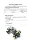
The experimental implemented circuit is shown in Fig
2. The most attractive feature is that contact less
communication is established with the authenticated
system placed completely inside the organization
security perimeter eliminating the chances of
external tampering of security devices.
Figure 2: Working System
Following notes are very important for the design.
Notes
•
The digital pins of the Arduino UNO board are
used for interfacing with the LEDs. As these pins
have internal resistances so no external resistors
are needed for digital pins reside in the board.
•
As we are using C++ like high level language to
program the system, the solution is easily
maintainable.
•
The authentication platform runs on low power
(5v, O.5A) making it suitable for long battery
based usage.
v.
Testing and Result
Step 1: The S2 Bluetooth mobile app is invoked in the
mobile phone running Android platform.
Result:
The mobile app opens on the mobile app. If the
Bluetooth of the mobile phone is not on, the app
would request to turn it on.
Step 2: The Arduino microcontroller board is powered
on.
Step 3: The sketch (code written for the Arduino
platform) is uploaded in the board. The sketch contains
a set ofmc.
Step 4: The Bluetooth of the Arduino and that of the
mobile phone is paired
•
Result:
The LCD display connected to the Arduino board
initially displays a text "Working well".
The Green LED is turned off and the Red LED is
turned on
The mobile app receives a text "power on".
Step 5: "<UIC>,<Information>" string is sent from the
mobile app
•
•
•
Result:
If the UIC matches with any one of the preloaded set
of UIC that is a part of the sketch,
The Green LED glows for 3 seconds and the Red
LED is turned off for that period.
•